AIRCRAFT INSPECTION FOR THE GENERAL AVIATION AIRCRAFT OWNER
CESSNA 414A · Checklist
Overview
This document is an Aircraft Inspection Handbook published by the Federal Aviation Administration (FAA) in April 1978. It is designed to assist aircraft owners, pilots, and mechanics in understanding the inspection processes and techniques applicable to general aviation aircraft, including the Cessna 414A. The handbook emphasizes the importance of regular inspections to ensure airworthiness and provides guidelines on how to conduct these inspections effectively. It covers various aspects of aircraft maintenance, including preventive maintenance, inspection fundamentals, and specific inspection techniques for different aircraft components. The document serves as a reference for establishing an inspection program that complements required inspections, ensuring the safety and reliability of the aircraft.
- Regular inspections are mandated by FARs, typically every 100 hours or annually.
- Preventive maintenance can be performed by certificated pilots and includes tasks like tire replacement and hydraulic servicing.
- Detailed inspection techniques are provided for various aircraft components, ensuring thorough checks for airworthiness.
- Preflight inspections are crucial and should cover all critical aircraft systems and components.
- Safety precautions must be observed during all inspections and maintenance activities.
Document
Source
Originally published by www.faa.gov. Sprinkle hosts a reference copy with an added summary, specifications and searchable full text.
Document details
- Type
- Checklist
- Year
- 1978
- Pages
- 92
- File size
- 33 MB
- Publisher
- www.faa.gov
Common. One of the most common aircraft types we track.
Most owners only have the POH. Here's the essential set for the CESSNA 414A.
- Pilot's Operating Handbook / AFM
- Checklist
- Maintenance Manual
- Parts Catalog (IPC)
- Systems & Wiring
- Service Bulletins
- Type Certificate (TCDS)
CESSNA 414A for sale now



Free — save the 414A to your watchlist and track it in one place.
More CESSNA 414Amanuals & documents
See all 13 →- Twin & Turbine - December 2024Other Documents
- Rosen Sunvisor Systems PMM / IPC for Sunvisor Assembly (p/n R1181300)Systems Description
- NACELLES/PYLONS - ENGINE NACELLE FITTING REPLACEMENTService Manual
- Cessna Flyer - Cessna 414A ChancellorOther Documents
- Rosen Sunvisor Systems CMM / IPC for Sunvisor AssemblySystems Description
- Airworthiness Directives; Cessna Aircraft Company AirplanesAirworthiness Directives
- Electronics International Inc Operating and Installation InstructionsWiring Diagram
- Specifications Subject to Verification/Inspection.Specifications
- 1979 Cessna 414A ChancellorPilot's Operating Handbook
- 1979 CESSNA 414A SALES BROCHURESpecifications
- Automatic Propeller SynchronizationWiring Diagram
- The Cessna 414A: A Reliable and Versatile AircraftMaintenance Manual
If you fly the CESSNA 414A, you may also be researching these.




In this document
Inspection Fundamentals
This section outlines the required inspections for civil aircraft as mandated by Federal Aviation Regulations (FARs). It discusses the importance of maintaining the aircraft's condition and the intervals at which inspections should occur, such as every 100 hours or annually. It emphasizes that inspections must be performed by certified personnel and provides a general overview of the inspection process.
Preventive Maintenance
Preventive maintenance refers to simple preservation tasks that can be performed by certificated pilots who own or operate the aircraft. This section lists specific tasks that qualify as preventive maintenance, such as replacing landing gear tires, servicing hydraulic fluid, and minor repairs that do not involve complex assemblies. It highlights the importance of regular maintenance to prevent more significant issues.
Inspection Techniques
This section details various inspection techniques applicable to different parts of the aircraft, including the fuselage, cabin, engine nacelle, landing gear, and wings. It provides specific checkpoints and procedures for inspecting these components to ensure they meet safety standards. The section includes illustrations to aid in understanding the inspection processes.
Preflight Inspection
The preflight inspection is a critical routine that pilots must perform before each flight. This section outlines the key items to check during the preflight, including fuel levels, control surfaces, and overall aircraft condition. It emphasizes the need for thoroughness to ensure safety before takeoff.
General Safety Precautions
This section provides essential safety precautions that should be observed during inspections and maintenance. It includes guidelines on using tools safely, handling hazardous materials, and ensuring proper procedures are followed to prevent accidents.
Safety notes
- Inspection should be performed by certified personnel to ensure airworthiness.
- Defects noted during inspections must be addressed by a certificated repair station or mechanic.
Full document text
AC 20-106 AIRCRAFT INSPECTION FOR THE GENERAL AVIATION AIRCRAFT OWNER . . ~~- . • APRIL 1978 U.S. DEPARTMENT OF TRANSPORTATION FEDERAL AVIATION ADM IN ISTRATION flight Standards Service For sale by t he Superintendent of Documents, U.S. Government Prin ti ng Office Washington, D.C. 20402 PREFACE The inspections described in this Aircraft Inspection hand book are NOT intended to replace any required inspection. Rather, they are intended to familiarize persons with the techniques generally applicable to aircraft in spections whether they be owner s, pilots, student mechanics, or others with aviation interests. The services of an appropriately rated certificated repair station, certifi cated mechanic, or the manufacturer must be utilized for all required inspec tions and whenever any in spection reveals a questionable condition. ''T e emphasize the fact that reliable in spection capability comes only with ex perience, and the use of this handbook does NOT qualify an individual to make final airworthiness determinations. PART I-INSPECTION FUNDAMENTALS Inspection requirements, owner 's responsibilities, inspection time inter vals, and sources of basic infor mation are discussed in Part I. PART II-INSPECTION TECHNIQUES The general techniques used to in spect an t>.ircraft are discussed in Part IT. To facilitate reference, in the explanation of important inspection pro cesses, arrows appear on many of the illust ration$. These indicate either the item or the general area to which the text refers. Numerous illustrations are used to co nvey i nformat ion to the reader in the most clear, graphic, and effective manner. Acknowledgment of cooperation is extended to the following: Beech Air craf t Corporation Cessna Aircraft Company Cessna Aircraft Company Aircraft Radio and Control Di vision Edo Corporation Piper Aircraft Corporation Rockwell International (Rockwell Commander Aircraft) The Bendix Corporation Electric /F luid Power Division The Goodyear Tire and Rubber Company This publication cancels the Personal Aircraft Inspection Handbook, AC 20-9, published in 1964. Suggestions for revision and improvement of this handbook are encouraged and may be forwarded to Dep artment of Transpor tation, Federal Aviation Administration, Flight Standards National Field Office, AFS-5 00, P.O. Box 25082, Oklahoma City, Oklahoma 73125. i AIRCRAFT INSPECTION FOR THE GENERAL AVIATION AIRCRAFT OWNER Contents Page Preface -------------- ---- --- ------ ------ --- ------ ---- ------ ------ i Part I. Inspection Fundamentals - ---------------------------------- 1 Section 1. The Inspection Process ------- ---------- ---- -- ----- 1 Section 2. Prev entive Maintenance --------------------------- 4 Section 3. The F orces o:f Attrition ----- ----- - ----------- --- --- 7 Section 4. In spection Do's and Don 'ts --- ------- ------ ------- - 14 Part II. Inspection Techniques __ _____ ___ .,:_____ ____ _____ ____________ 15 Section 1. Section 2. Section 3. Section 4. Section 5. Section 6. Section 7. Section 8. Section 9. Fus elage ------------------------------------------ 15 Cabin-Cockpit - ---- ------- -------------- ---------- 21 Engine Nacell e------ -- ----- -------- - -- --- ------ -- - 27 Landing Gear--- -- - ------ --- ------ -- --- ---- ---- --- 42 Wing-Center Section -- - -- ---- - -- -- ------ ---- ---- -- 53 Empennage --- - -- - ------- -- ------- --- ------ -- ----- 61 Pr~peller ------------------------ - ----- ---------- - 66 Radio - --- ---- -- --- ---- -- ----- ---- -- -- ------ --- --- 71 Miscellaneous -- - - -------------------------- - --- -- - 75 Section 10. Preflight Inspection - - ------ -- ------ - ------ - -- - -- -- 77 Section 11. After Storage - - -- - -- ------ -------- -- --- ------ -- --- 80 APPENDIX A. APPENDIX B. APPENDIX C. APPENDIX D. Figure General Safety Precautions --- --- -- ---- ---- -- ---- 81 Aviation Fuel-Identification and Fueling Proce dures - - ----- - -- ------- - ------.- --- -------- -- ---- 83 Certificate of Registration-Aircraft Eligibility and Application - - - --- ------ ----- ----- -------- - --- -- 85 Certificate of Airworthiness-:..General Information 87 List of Illustrations PART I. Inspection fundamentals Page I-1. Five stresses acting on aircraft -- --- ----- -- - ---------- - - - ---- 10 Part II . Inspection Techniques Section 1. 1-1. Inspection chart-fuselage --------- ---- ----- ---- ----- -- -- --- 15 1-2. Cracked fuselage structure ------ ------------- ----- ---- --- --- 16 1---3. Cracked former --- ---- --- - ---- ------- -- ----- --- -- - - -- - - ---- 16 1-4. Distorted fu selage sk in -- - ---------------------------------- 16 1-5. Deteriorated fuselage :fabric ---- --- - - -- ----- - - -- -------- - --- 16 111 Figure Page 1-6. External wing bracing attachment checkpoints -------------- 16 1-7. Proper cable routing -------------------------------------- 17 1-8. Improper cable routing - ----------------------------------- 17 1-9. Proper routing of electrical wiring ------------------------- 17 1-10. Improper routing of electrical wiring ----------------------- 18 1-11. Leakage from chafed hydraulic line ------------------------ 18 1-12. Draining fuel tank s ump ---------------------------------- 18 1-13. Doorlock checkpoints-------------------------------------- 19 1-14. Emergency exit checkpoints ------- - ----------------------- 19 1-15. Interior aft fu selage (light twin) --------------------------- 20 Section 2. 2--1. Inspection cha rt-cockpit ------------------------------------ 21 2-2. Ins pection chart-cabin - -- - ---------------------------------- 22 2--3. Operational check-fuel tank selector valve ------------------ 22 2--4. Circuit breaker and fuse panel ------------------------------ 23 2--5. Check quantity hydraulic fluid -------------------------- --- - 23 2-6. Instrumen t panel ---------------- --- ----------------------- 24
Show full textShow less
2--7. Bellcrank checkpoin ts -------- ------ ---------------- ------ -- 24 2--8. Cable rubbing bulkhead - - ---- --- ----------------- -- - -- ----- 24 2--9. Gustlock ---.. ----------- - ---------------------------------- 25 2-10. Frayed safety belt ----------------------------------------- 25 2-11. Safety harness --------------------------------------------- 25 2-12. Inspection items on seat ---------------------------------- - - 25 Section 3. 3-1. Inspection c hart~ngine and nacelle ------------------------ 27 3-2. Inspection chart~ngine -- ---------- ----------------------- 28 3-3. Fuel strainer checkpoints ---------------------------- ------ - 29 3-4. Carburetor inspection points -------------------------------- 29 3-5. Carburetor air filters --------------------------------------- 30 3-6. Intake manifold checkpoints -------------------------------- 30 3-7. Oil tank inspection ----------------------------------------- 30 3-8. Oil quantity check -------- --------- ----------------------- - 31 3-9. Satisfactory oil line installation ---------------- ---------- - - - 31 3-10. Unsatisfactory oil line installation -------------------------- 31 3-11. Oil-cooler checkpoints -------------------------------------- 32 3-12. Checking sparkplug torque --------------------------------- 32 3-13. Unsatisfactory sparkplug cigarette -------------------------- 33 3-14. Igniter plug-gas turbine engine ---------------------------- 33 3-1 5. Exhaust manifo ld checkpoints ------------------------------ 33 3-16. Exhaust stack damage - ------------------------------------ 34 3-17. Heat exchanger-shroud removed ---------------------------- 35 3-18. Cowl flap checkpoints --------- -- --------------------------- 36 3-19. Engine baffies ---------------------------------------------- 37 3-20. Engine mount checkpoin ts ---------------------------------- 37 3-21. Cracked engine mount ----- --- ---- - -- ------------- - - - - -- --- - 37 3-22. Checking starter security -- --------------------- ----- ------- 38 3-23. In spect cowling for damage -------------------------------- 39 3-24. Damaged cow ling ------------------------------------------ 38 iv Figure Page 3-25. Repaired cowling ------------------------------------------ 39 3--26. Cowling installation checkpoints ---------------------------- 40 3-27. E vidence of chafing ---------------------------------------- 41 3-28. Battery installation checkpoints ---- - --- --------------------- 41 Section 4. 4-1. Examples of tire defects ------ - -- --- -- --- ---- --------------- 42 4--2. . Tire prot ected by d:rip pan --------------- - ------------------ 42 4-3. Multiple disc-type brake'------------------------------------ 43 4-4. Shoe and drum-type brake----,--------------------,---------- 43 4-5. Expander block-type brak e --------------------------------- 43 4--6. Di sc brake inspection points -------------------------------- 43 4-7. \Yheel and brake in spection points -------------------------- 44 4-8. Hydraulic brake line checkpoint s -------------------- -- --- - -- 44 4-9. Simple master cylinder brake systems ------------- --- -- --- - -- 44 4-10. Cockpit-hydraulic brake line checkpoints -------------------- 44 4-11 . Wbeel checkpoints - --- --- -- --- -- --- -------- ------ - - ------- - 45 4--12. In spection chart-fixed landing- gear -------- -- -- - --- -- -------- 45 4-13. Fixed nose ~ear checkpoints ------------ --- --------------- -- 46 4--14. Oleo-type landing gear checkpoints -------------------------- 46 4-15. Steerable tailwheel inspection points ------------------------ 47 4-16 . Inspection chart-retractable landing gear ----------------- - -- 48 4-17. Retract able main gear checkpoints -------- --- -- - ------------ 47 4--18. Landing gear retracting - -- --- ------ -- --- -- --- - --------- - --- 49 4--19. Retractable nose gear checkpoints -- - --- -- --- - - -- -- - -- ---- - -- 50 4-20 . Retracting mechanism checkpoints - - ------ -- ---- --- - -- --- -- - 50 4-21. Typical electrical retraction installation ---- - ---- -- --- -- --- -- - 50 4--22. Electrical retracting motor and wiring ---- -- --- - ---- -- --- -- - 51 4-23. \Varning microswitch installation - ------ -------- -- ----------- 51 4-24. Gear attachment structure checkpoints --- - ---- - ---------- -- - 51 4--25. Float in stallation inspection points - - - --- - -- - - - - ---- -- --- ---- 51 4--26. Ski installation inspection points - --- - ---- --- ---- - -- - ---- - --- 52 Section 5. 5-1 . Inspection chart-wing-center section - - ---------- - - --- -- ------ 53 5-2. Indication of defective fabric------- -- ---- - -------------- - -- 54 5-3. \Vood structure inspection po in ts-- -- - ------ - - - --- ----------- 54 5-4. Metal structure inspection points --- - - --- - -- -------------- -- - 55 5-5. Lighting damage-flap, lo,ver surface -- --- - -- ---- - ---- ---- - - -- 56 5-6. Control bellcrank checkpoints -- --- -- ---- - ---- ---- ------- ---- 55 5-7. Fuel tank vent -- --- - - - --- - --------- -- ------ - - -- ---- - ------- 57 5-8. Fuel cap, vent , and placard---- - -------- - ---- - ----------- -- 57 5-9. Pitot mast, airspeed -- ---- - ------- -- ---- --- --------- -- ---- - 58 5-10. Ele ctrical wiring, proper routing ---- - -------------- - ---- --- 58 5-11. Satisfactory leading edge of wing --------- ---- - ---- ---- - - -- 58 5-12. Dented leading edge of wing -------- --- ------ --- ----------- 59 5-13. Damaged landing light lens --- -- --- - --------------- -- ---- - 60 5-14. Deicer boot damage -- ---- - - ----- - -- --- -------- - - ------- -- - 60 5-15. Block type gust lock ----- - -- -- ------------- --- - -- ------ ---- 60 v Figur e Page Section 6. 6-1. Inspection chart--empennage ------------------------------ 61 6-2. Oilcanning of metal skin ---- - ----------------- - ----------- 62 6-3. External bracing checkpoints --------------- -- ------------- 63 6-4. Rudder checkpoint s _----- ----'------- - -- ------------------- 63 64 6-5. Rudder quadrant . - ---------- - ----------------------------- Stabilizer adjuster checkpoints _________ .;. ___________________ _ 6-6. 65 6-7. Position light checkpoints _____ ----------------------------- 65 Section 7. 7-1. Inspection chart-propeller--------------------------------- 66 7-2. Damaged metal blade ---- --- ------- --- ------ -- ------- - ----- 66 7-3. Three-blade propeller checkpoints------------- - ---------- - -- 67 7-4. Propeller tip damage ----- - -------------------------------- 68 7-5. ·wood propeller blade-cracked and separated lamination ------ 68 7-6. Propeller governor checkpoints ------------- ~-- ------- -- ---- 69 7-7. Propeller sp inner checkpo int s ------------------------------- 69 7--8. Propeller liqui d anti-icing system checkpoints----------.,.----- 70 7-9. Propeller electrical deicing system checkpoints---------------- 70 Section 8. 8-1. Inspection chart-rad io ------------------------------------ 71 8-2. Communication / navigation equ ipment installation che ckpoints _ 71 8-3. Bonding radio equipment to shock mount --- -- - ------- -- ----- 72 8-4. Com muni cation/ navigation equ ipmen t shock moun t ---- --- ---- 72 8-5. Typical communication / na v igation equipment control --- -- - - -- 72 8-6. Antenna insta llations checkpoints ---- ---- - --- ---- -- --- --- - -- 73 8-7. ADF antenna-internal loop- tail mount - -- - ---- -- ---- ----- --- 73 8--8. ADF antenna-fixed loop -- ------ --- -- - --- -- - -- ---- -------- 73 8-9. Bondin g wires and trailing edge static wicks - -- ------- -- ----- 74 Section 9. 9-1. Rotating beacon in stallation -- - - ----- ---- - - ----------------- 75 9-2. Autopilot control panel---- --- ----- ---- ------- ---- - ---- - - - -- 75 9-3. Emergency locator transmitter-remote mount -- --------- ---- 75 9-4. Emergency locator transmitter-portable mount ---------- - -- - 76 Section 10. 10-1. Inspection c hart-pr eflight 77 Section 11. 11-1. Bird's nest --- -- -- --------- -- - - ----- ---- ----------- -- - - ---- 80 Part I. INSPECTION FUNDAMENTALS Section 1. THE INSPECTION PROCESS The Required Aircraft Inspections The Federal Aviation Regulations (FARs) require the inspection of all civil aircraft at specific intervals, to assure that the aircraft's condition is equal to its original or properly altered condition with regard to aerodynamic function, str:uctural strength, and resistance to vibration. Inspection interval requirements are estab lished considering the purpose for which the aircraft is used and its operating environment. Some aircraft must be inspected each 100 hours of time in service while others must be in spected only once each 12 calendar months. The 100-hour and annual inspections require complete inspection of the aircraft at one time and a certification as to its airworthiness. Some airplanes may be inspected in accordance with a progressive inspection (FAR 91.171) or an approved inspection program (FAR 91.217) wherein portions of the aircraft are inspected according to a predetermined schedule. The inspection requirements for aircraft, in various types of operation, are stated in FAR 91, Sections 91.169, 91.171, or Subpart D of FAR 91. The latter prescribes an inspection program for large and turbine-powered multi engine airplanes (turbojet and turboprop). If you are concerned with the inspection of a large airplane (over 12,500 pounds) or a turbo jet or turbopropel~er-powered multiengine air plane, you should determine the inspection requirements for that specific airplane. The information contained in Section I of this handbook may not be directly applicable to these larger type airplanes, but the inspec tion techniques will be similar. FAR 91-General Operating and Flight Rules. Subpart C of Part 91 prescribes rules gov erning the maintenance, preventive mainte nance, and alteration o£ U.S. registered civil aircraft operated within or outside the United States. (Inspection is part of maintenance.) FAR 43-Maintenance, Preventive Maintenance, Rebuilding, and Alteration, prescribes rules gov erning the maintenance, preventive mainte nance, rebuilding, and alteration of aircraft as well as standards for their performance. Inspection. Inspection is the critical visual exammmg, testing, measuring, and functional checking re quired to determine the airworthiness of the items being inspected. NOTE; As n!('ntioned in the prefa ce , the serv ices of a certificated repair station, certificated mechanic, or the manufacturer must be utilized for all required inspections and whenever any inspection r eveal s a questionable condition. Scope of Inspections. Aircraft inspection may range from a casual "walk-around" to a detailed inspection involv ing complete disassembly and the use of com plex inspection aids. The inspections des_cribed in this advisory circular can be made without disturbing the assembly of the aircraft except for the removal of inspection access covers, fairings, and removable cowlings. The Habit of Inspection. Tlie inspection of your aircraft should be come a habit. To establish the habit, begin by performing preflight inspections and work up to detailed inspections. USE the MANUFAC TURER'S RECOMMENDATIONS and this handbook as a guide. Develop a system of 1 319 -4 70 0 - 80 - 2 inspection and use. an inspection checklist that covers the complete aircraft. Once adopted, you should not deviate from the procedure. After completing a few inspections you will be surprised at how familiar you will be with your aircraft. Inspection Intervals and Systems. Federal Aviation Regulations require inspec tion of aircraft at specific intervals and that they be approved for return to service by cer tificated and appropriately rated personnel. The purpose of this handbook is to familiarize interested persons with general inspection tech niques and to assist pilots and owners in estab lishing an inspection program which will supplement but NOT replace the required inspections. The interval of your inspection should be adjusted to provide the greatest value to you considering your aircraft use and the required inspections; e.g., if you are required to have 100-hour inspections, you might want to in spect the aircraft each 25 and 50 hours. If you are required to have only annual inspections, you may wish to inspect the aircraft each 50 to 100 hours of operation. The manufacturer's service instructions will be valuable in estab lishing these intervals. Historically, inspection intervals have been established on the basis of flying hours. How ever, if utilization is low and flying is done over the weekends, you may find it advisable to inspect a small group of items each weekend. This will spread your inspection over a period of time and reduce large demands on your time. Here are some examples of types of inspection intervals : By hours: Daily preflight inspection Powerplant (including propeller and engine controls)-every 25 hours Flight control systems-every 25 hours Landing gear-every" 50 hours Cabin or cockpit-every 75 hours Covering (fabric or metal)-every 100 l1ours Fuselage interior-every 100 hours, etc. By calendar weeks (eight-week cycle) : Daily preflight inspection (including propel· ler and engine controls) Powerplant-first and fifth weekend Flight control system-second and sixth weekend Landing gear-third and seventh weekend Cabin or cockpit-fomth and eighth week end Covering (fabric or metal)-eighth weekend Fuselage interior-eighth weekend This weekly inspection schedule will provide a complete aircraft inspection every eight weeks. You may wish to extend or shorten this inspection cycle. In some cases, it may be convenient to estab lish a combination of both methods. Regard- . less of the method chosen, adhere to it faithfully. Do not assume that an item is in good condition. Make a personal inspection each time an inspection is due, according to your plan . There are many inspection items; each of which is essential. "When developing an inspection schedule for your aircraft, 'consideration should be given to climatic conditions, frequency and type of flight operation conducted, contemplated pe riods of inactivity, and type of storage facili ties. A thorough review of the aircraft manufacturer's service instructions will provide many helpful suggestions on inspections. Most manufacturers provide an inspection schedule for their aircraft which can be segmented as you desire. The information in this handbook will not tell you WHEN to inspect. It will suggest WHAT should be inspected and HOW and WHERE to look for possible defects. Be sure your plans include the time neces sary to regularly inspect your aircraft. If such time cannot be included ' in your plans, then you should have it done by certificated personnel. "'When you have inspections conducted by a professional, whether they are required or sup plemental in nature, you should specify exactly what inspection is to be accomplished and re quire the person conducting the inspection to furnish a written statement of the results. 2 Aircraft Logs. "Logst as commonly used, is an inclusive term which applies to the aircraft record "books/' and to all supplemental records con cerning the aircraft. These logs and records provide a history of maintenance and opera tion, a control for inspection schedules, data needed to properly accomplish time replace ments of components or accessories, and a record of Airworthiness Directive compliance. Most Airworthiness Directive compliance is based on aircraft time-in-service, and it is a regulatory requirement that records be kept up-to-date. Tools of Inspection. The tools of inspection are many and varied. They range from a pocket-sized magnifying glass to a complex X-ray machine. The tools required to make a simple inspection, of the type which may be performed by the aircraft owner, are inexpensive and readily available. The following list is typical: eight or ten-power magnifying glass inspection mirror flashlight small wire brush dull-bladed knife round bristle brush and cleaning fluid (use caution when selecting cleaning fluids) hydrometer some rags small kit of common handtools (screwdriver, end wrenches, diagonal cutters, etc.) skid-proof stepladder and wheel jacks REMEMBER If defects are noted or suspected, have a detailed inspection done by a certificated repair station or certificated mechanic. 3 Section 2. PREVENTIVE MAINTENANCE Preventive maintenance means simple preser vation and the replacement of small standard parts not involving complex assemblies. It is corrective action taken before it becomes neces sary to make more complex repairs. The following preventive maintenance may be ac com:plished by a certificated pilot, who is the owner or operator of an aircraft, not used in . . .a1r earner serv1ce. This list comes from FAR 43, Appendix A , Major Alterations, Major Eepairs, and Preven tive Maintenance, paragraph (c). It reads as follows: " (c) Preventive maintenance. \Vork of the following type is preventive maintenance: (1) Removal, installation, and repair of landing gear tires. (2) Replacing elastic shock absorber cords on landing gear. (3) Servicing landing gear shock struts by adding oil, air, or both. (4) Servicing landing gear wheel bearings, such as cleaning and greasing. (5) Replacing defective safety wiring or cotter keys. (6) Lubrication not requiring disassembly other than removal of nonstructural items such as cover plates, cowlings, and fairings. (7) Making simple fabric patches not re quiring rib stitching or the removal of structural parts or control surfaces. (8) Replenishing hydraulic fluid in the hydraulic reservoir. (9) Refinishing decorative coating of fuse lage, wings, tail group surfaces (ex cluding balanced control surfaces), fairings, cowling, landing gear, cabin, or cockpit interior when removal or dis assembly of any primary structure or operating system is not required. (10) Applying preservative or protective material to components where no dis assembly of any primary structure or operating system is involved and where such coating is not prohibited or is not contrary to good practices. (11) Repairing upholstery and decorative furnishings of the cabin or cockpit in terior when the repairing does not re quire disassembly of any primary structure or operating system or inter fere with an operating system or affect primary structure of the aircraft. (12) Making small simple repairs to fair ings, nonstructural cover plates, cowl ings , and small patches and reinforce ments not changing the contour so as to interfere with proper airflow. (13) Replacing side windows where ,that work does not interfere with the struc ture or any operating system such as controls, electrical equipment, etc. (14) Replacing safety belts. (15) Replacing seats or seat parts with re placement parts approved for the air craft, not involving disassembly of any primary structure or operating system. (16) Troubleshooting and repairing broken circuits in landing light wiring circuits. (17) Replacing bulbs, reflectors, and lenses of position and landing lights. (18) Replacing wheels and skis where no weight and balance computation is in volved. (19) Replacing any cowling not requmng removal of the propeller or disconnec tion of flight controls. 4 (20) Replacing or cleaning spark plugs and setting of spark plug gap clearance. (21) Replacing any hose connection except hydraulic connections. (22) Replacing prefabricated fuelline!i. (23) Cleaning fuel and oil strainers. (24) Replacing batteries and checking fluid level and specific gravity. (25) Removing and installing glider wings and tail surfaces that are specifically designed for quick removal and instal lation and when such removal and in stallation can be accomplished by the pilot." Technical data for use in performing preven tive maintenance may be found in the manu fa cturers' manuals. General data on aircraft maintenance may be obtained from the follow ing Advisory Circulars (AC) published by the FAA. All are available from the Superin tendent of Documents (Supt. Docs.) and should be ordered by the stock numbers (SN) listed after each AC. AC 65-9A , Airframe and Powerplant Meclt.an ics General Handbook, is designed as a study manual for persons preparing for a mechanic certificate with airfram e or powerplant ratings. Emphasis in this volume is on theory and methods of application. It is intended to pro vide basic information about principles and fundamentals common to both the airframe · and powerplant ratings. (S~ 050- 007-00379. 0.) AC 65-J2A, Airframe and Powerplant Me chanics Powerplant Handbook, is designed to familiarize student mechanics with the con struction, theory of repair, operation, and maintenance of aircraft powerplants and pro pellers. (SN 050-007-00373-1.) AC 65-J SA, Airframe and Powerp#ant Me chanics Airframe Handbook, is designed to fa miliarize student mechanics with construction, theory of repair, operations, and maintenance of airframe and airframe systems. (SN 050-007-00391-9.) Advisory circulars are available either free from F A.A. or sold by the Superintendent of Documents. The source, ordering in structions, and current pri ces are listed in t he FAA Ad visory Circular Checklis t, AC 00- 2. The checklist should be consulted for curren t infor mation before placing any orders. (A refer ence copy is available at any FAA office or GPO Bookstore.) · The checklist is published three times a year and is available free fr om Department of Transportation , Publications S ec tion, ~1-443.1, Washington, D.C. 20590. The Status of Federal Aviation Regulations, AC 00-44, is issued as changes require anrl is also available free from · the abo\·e address. Nlalfuncfion or De#ecl Reports (FAA Form 8330-2) are provided free of charge a nd with retum postage paid by th e F A.A. They are normally preaddressed when provided, and are a convenient means of ens uring that data, re quired to make the repo1;t meaningful, is in cluded. These reports are a means by which the aviation community may interchange service information since the data r eceived on the re ports is published in numerous FAA publica tions, available free or on a sub sc ription basis. Malfunction or Defect Reports are also a data SOUJ:<!e used by the FAA in monit oring the service reliability of aeronautical products. 'Vhen trends are noted which indicate possible problem areas, the FAA may ale rt the aviation commun ity or initiate studies to determine the extent and exact nature of the problem. All aircraft owners, pilot s, mechanics, and non-certificated maintenance facilities are in vited to participate in the program by submit ting M or D ·. Reports whenever they become aware of items that may be of interest to others. The M or D Repo rt s, FAA Form 8330- 2, may be obtained from most airport managers, main tenance facilities, or any FAA Di strict Offic~. If you have had an experience you wish to share, include in th e report all information available; how the occurren ce became apparent, describe the malfunction, and include model numbers, part numbers, and serial numbers. 5 Parts may be submitted with the report by special arrangement. Pictures, sketches, or snapshots are especially desirable. Include identification .data such as make, model, and assembly name as an attachment rather than printing on the photograph. H you have any questions, or need any help, you~· local FAA District Office will gladly assist you. The success of the program depends entirely on participation hy the aviation public. If you have comments about the program or have a special experience or a "v,· ould. you believe this'' situation, send them to Federal Aviation Ad ministration, Flight Standanls X ational Field Office, Safety Data Branch~ _\.FS-580, P.O. Box 25082, Oklahoma City, Oklahoma 73125, 6 Section 3. THE FORCES OF ATIRITION A Definition of Attrition. Attrition, for the purpose of this handbook, is defined as the general wear and tear of an aircraft during its service life. The five basic sources of attrition are: weather, friction, over loads, heat, and vibration. These forces assert themselves in many ways on the entire struc ture of the aircraft during its life span. Per sons making inspections should be familiar with the visible, measurable, or otherwise de tectable effects of these forces. Weather. Much depends on local conditions such as heat, humidity, rain, wind, and snow. Each element, or combination of elements, has its own peculiar effe~t upon uifferent parts of the aircraft. These effects are discussed briefly in the following paragraphs. Atmospheric Moisture. The moisture content of the atmosphere is directly related to the severity of oxidation found on an aircraft. Aircraft based near large bodies of water or in areas receiving heavy rainfall are more sus ceptible to oxidation (rusting and corrosion) than those based in. arid areas. Fabric surfaces and wood structures also decay due to at mospheric conditions. Oxidation. This condition is caused by the chemical combination of metal and oxygen. Oxidation is called rusting when talking about ferrous materials; i.e., steel or iron. The oxi dation of copper, aluminum, and other non ferrous materials is usually known as corrosion. Rusting. Rust usually begins as a reddish discoloration on the surface and, if permitted to progress, will result in a reddish brown crustiness on the metal surface. Removal of the crust will probably reveal pitting. If pitted, the part should be examined by an ex perienced mechanic qualified to evaluate the extent of the damage and recommend or take corrective action. The steel tube members of an aircraft equipped with floats should be given par ticularly close ~xamination. It is possible for water to enter the interior of these members, allowing rust to form on the inside of the tubes while the exterior appears to be in good condi tion. The best way to check for this condition is to have small holes strategically drilled in the tubing. If water is present, it will run from the holes. It is sometimes desirable to have small pieces cut from critical tube mem bers in order to obtain positive knowledge of the condition of the tube interiors. CAUTION Tests of this ncdure should be performed by, or under the supervision of, a certificated mechanic or repa :r station and entered in the aircraft records. Speciali%ed experience and sk:IJ are required to determine where water is most apt to concentrate, and where and how to drill the tubing. Rusting may be prevented or retarded by applying a protective coating to prohibit the atmosphere from coming in contact with the bare metal. This is usually accomplished by electrolytic plating or the application of a zinc base paint. Plating may only be accomplished by certificated personnel. The interior of steel and aluminum struc tural tubing is protected by flushing with hot linseed oil, paralketone, or other corrosion in hibitors. The holes drilled for this operation are usually plugged with sheet metal screws (see CAUTION above). Corrosion. Aluminum, magnesium, and other nonferrous metals are susceptible to corrosion whenever the protective coating deteriorates. Deterioration is accelerated whenever the coat· 7 ing is in contact with an eroding chemical such as battery acid, insecticide, fertilizer or de foliant s. Contact between two unprotec ted di ssimilar metals sets the stage for galvanic action and corrosion, the rate of which in creases great ly in the presence of moisture, especially saltwater . Ordinary corrosion of aluminum, magne sium, or aluminum alloy parts can be detected by watching for signs of surface flaking, pit ting , or a white or grayish-white powdering. I:f pitting is apparent. after removing the flakes or powder film, an experienced mec hanic should be contacted to evaluate the damage. On aluminum a nd magnes ium (or their alloy s) s urface s that have been painted , watch for paint bubbles or blisters. These indi cate cor rosion under the paint. The suspected part should be cleaned to the bare metal and exam- . ined carefully. Decay of Wood Structure. The protecti ve coating on wood structures usually consists of high grade va rni sh or some typ e of tran s par ent enamel. An acceptable coating w·ill have a hard glossy appearance. ·whenever and wher ever the prot ective coating deteriorat es, decay will s tart . H e althy wood will sp li nter if probed wit h a dull knife point. Decayed wood will crum ble or break away in chunks. vVeathe ring of the s tructure· is first indicated by a dull appearing s urfa ce, which means that the protective film has broken down. Be especially alert to wooden compone nt s subject to the collection of moisture and / or poor ventilation . Decay of Fabric. The decay of fabric is somewhat similar to the decay of wood. If exposed to the elements, fabric absorbs mois· ture and other harmful substances unless it is protec ted by seve ral applications of cellulose nitrate or cellulose acetate, liquids commonly known :l.S "dope." vVhen "do pe " is applied, it acts to tighten the fabric a nd produces a hard , smooth, opaque finish. In time , thi s finish be comes brittle and de vel ops crack s which expose the bare fabri c to th e harmful effects of ul tra violet light, dirt, oil, and mildew. The s trength of the fabri c decreases to below minimum str •h and is no longer airworthy. Th e effect of decay on finished fabric s ur f aces can be ascertained o nl y by testing. To determine if a test is necessary, examine the f ab ric surface . If the sm fa ce no longer pre sents a hard flexible glossy finish! is seve rly abraded, or crack fi are present, t es ting is ap propriate. A manual punc h test, performed by a quali fied repair st ation or mechanic, will p rovide an indication of fabric streng th. .A conclusive tes t can only he done hy a recognized testing labora tor y, where in fabric sa mples are tested und er specified temperatu re and humidity conditions. If lab o ratory test facilit ies are not readily avai lable, contact );our local FAA inspector for information in their regard. Since re-coveri ng a s urfa ce is u sually an ex pensive process, economics dictate s the practice of good preventive maintenance. 'V a shing fabric-covered surfaces with mild soap and ' vater, at reasonable int erva ls, will do much to prolong the lif e of dope a nd fabric. Prote c tion from sunli ght also prolong s fabri c lif e, since ultr aviolet li g ht is a prime fa c tor in f abric deteri oration . Friction Fri ction is de scribed as the resistance to rela tive motion between two bodies in c ontact. Lik e an y machine, the ai rc raft develops fric tion in hundreds of moving part s. The effect of fri ct ion on the aircraft and it s components is known as wear. 'Year cannot be prevented, but s tep s can be taken to deter it s ultimate effects on the aircraft 's ai rw orthiness by proper lubrication, alignment of m oving part s, and cleanliness. To better understand in spection techniques, the terms used to de scribe the var ious cond iti ons of wear, du e to fri ct ion, must be under stood. They are as follows : Abrasion is a for m of wear cau sed by the presence of an abra sive substance between two mov ing parts. In t he fl.igh,t co ntrol system, the possibili ty of ab rasion c an be detected by a g ritty, g rinding sen sat ion noticeable during ope ra tion. Landing gear joints subjected to abras ion may exhibit an uneven jerky action .· when in mot ion. Csually a black gritty sub stance wi ll be noti ced at any joint subjected to abrasion. 8 Burnishing is the polishing of a surface by sliding contact with another smooth, harder metallic surface. Usually there is no displace ment or removal of metal. Burnishing is prob ably the least serious of friction-caused prob lems; however, it should be very closely monitored. In can be considered a warning of an impending more serious condition-gall ing, which is discussed later. Chafing is the >vear behveen two parts caused by the rubbing, sliding, or bumping of one on the other. The term is normally used to de scribe wear between parts not normally in contact. Chafed fabric, wood, or metal can be detected easily since chafing usually marks one or both parts involved. Metal parts, when chafed, show a bright area where contact has been made. Aluminum parts normally display a black or dark gray residue around the point of chafing. The simplest method of inspecting for chafing is to carefully inspect cables, wires, tubes, etc., wherever they are in close proxi mity to another part or when they are mounted to permit motion. Cutting results in cuts or grooves in the worn part. The cause of cutting is similar to chafing except that a sharp edge is in contact, instead of a smooth surface. Dent is an indentation in a surface produced by an object striking with force. The areas surrounding the indentation 'vill usually be slightly upset. Areas especially susceptible to dent damage are the propeller, spinner, nose contour of engine covding, nose cone of fuse lage, and the leading edges of wings, horizontal and vertical stabilizers. Elongation is the term used to describe the egg-shaped wear of a bearing surface around a bolt, hinge pin, clevis pin, etc. It results in looseness in one plane of motion greater than that o:f the other planes. Flight control sur face hinges, engine control rod ends, flight con trol push-pull rod ends, bellcrank ends, cable clevis ends, and similar parts are particularly susceptible to this type of wear. For example, an elevator may have the con trol cable rigged so taut that a positive pres ::oure is applied on one side of the hinge. Dur ing normal operation, the hinge bearing will wear egg-shaped due to the hinge pin rotating under a thrust load imposed by the cable. Erosion is the loss of metal :from the surface by mechanical action of foreign materials, such as fine sand or water . The eroded area will be rough and may be lined in the direction in which the :foreign material moved relative to the surface. Aircraft operated from unim proved airports are particularly susceptible to erosion, primarily on propellers, landing gear, cowling, anrl leading edges of wings and stabilizers. Galling is the breakdown (or buildup) of metal surface due to excessive friction between two parts having relative motion. Particles of the softer metal are torn loose and "welded" to the harder metal. Galling quite often be gins as burnishing. Gouge. A gouge usually involves material loss but may be largely the displacement of material and results from contact with foreign material under heavy pressure. ScraJch. A slight tear or break in material surface from light momentary contact with foreign material or object. Score is a deeper (than scratch) tear or break in metal surface from contact under pressure. It may show di scoloration from the temperature produced by friction. The term is normally used to describe conditions on parts designed to run together; i.e., a worn bearing might score the shaft. Tear is a discontinuity which has progressed through the full thickness of the material. Overload. Aircraft are designed to absorb the loads imposed during normal operation and accept a certain amount of overload. Excessive loads, however, result in failure or deformation of the structure. This deformation may be slight or prominent, but it is usually visible. In any case, it can be detected and classified by certain appearances peculiar to the type of overload applied. 9 In the majority o£ cases, loads which result in deformed ·parts also overload the adjacent structure. Because o£ the possibility o£ hidden damage, a qualified mechanic, repair station, or the aircraft manufacturer should be called Types of forces. A. Tension C. Torsion Bent structural member E. Bending upon to make a detailed inspection when de formation is noted. This is especially true when an aircraft has been in an accident or subjected to suspected overloads on the struc ture . B. Compression D. Shear Tension (outside of bend) FIGURE I -1. Five stresses ading on aircraft. 10 Tension. 'When a load is applied at either or both ends of an item, tending to pull it apart, it is loaded in tension. Overloads due to ten sion usually occur after a hard landing, taxiing on a rough field, or during flight in very tur bulent air. After a hard landing, all attach ment fittings should be examined for tension failures or deformation. Failure is indicated YJl attachment fittings which show signs of Julling away from fuselag-e structure or failure .n a welded area, and bolt holes 'vhich are elongated or torn. '\Velds are particularly sub ject to failure under tension loads and should be closely inspected. In aircraft of all metal construction, over loads are usually evidenced by wrinkling of the metal skin, around wing, stabilizer and landing gear attachment points, and deformed or cracked fittings. 'Ving struts are in tension during normal flight conditions and when severe vertical cur rents or gusts are encountered, they may be subjected to heavy loading. The strut attach ment points, at the wings and fuselage, should be carefully examined for the indications of failure described for landing gears. Compression. A part subject to compression loads tends to fail (bulge) at the weakest point in overall length or span, at right angles to the application of the overload. Compression failures are usually found after a hard landing, flight through turbulent air, or an 'accident, and affects the same areas refer enced under tension in the previous paragraphs. A bulge is indicative o£ compression failure; however, it is not always noticeable. In this event, a break in protective paint coating may be present. Sheet metal and extruded mem bers will show some form of distortion when damaged by compression. In long members such as wing struts, compression may be first evidenced by what appears to be a bow or bend in the member. A compression overload of a wood member can usually be detected by a slight ridge across the face of the member at right angles to the direction of the grain. Torsion is a twisting force that tends to turn one end of a part about a longitudinal axis while the other end is held fast or turned in an opposite direction. \Yheels caught in frozen ruts during a landing will tend to twist the landing gear members. Severe air loads im posed during abnormal flight maneuvers or flight through turbulent air may twist the con trol surfaces or other components. Improper rigging adjustments to wings ancl tail surfaces may also cause twisting of these components. The inspection, in these cases, is similar to that described for tension and compression over loads. Certain landing gears employ a torsional member referred to as a "scissor," "nut cracker," or "torque link'' Careful inspection should be made of this assembly for loose bolts and cracks, especially after landing in a rough or rutted field. Shear. An action or stress resulting from forces applied so as to cause a portion of a part to move relatively to another portion in a di rection parallel to the direction of the force. This action is normally found in tools such as bolt cutters or sheet metal shears which apply the force and shear the material being worked. ·when an overload is applied , the part having the least resistance to the force will be the first to fail. For this reason, bolts, rivets, and clevis pins should be examined for signs of failure. This is especially important when it is found that the overloaded members do not show the usual indications of failure. Failed bolts, clevis pins, and rivets may shear or partially shear and yet appear perfectly normal to the casual observer. To check for this condition~ the following hints may prove useful: 1-Bolts and Olevis Pin.s-Removal and in spection is a positive check for condition. Removal of bolts, clevis pins, etc., is es pecially difficult if deformed or otherwise damaged by excessive shear loads. 2-Rivets-Loose or sheared aluminum rivets may be identified by the presence of black oxide which is caused to form rapidly by working of the rivet in its hole. This oxide will seep out from under the rivet head to stain the surrounding surface. Pressure applied to the skin adjacent to the rivet head will help verify the loos ened condition of a rivet. 11 Bending is a force or combination of forces that will cause a rigid member to curve or bow away from a straight line. Overloads which cause bending are usually the result of ab normal landing and flight loads, or improper ground handling of the aircraft. Bent com ponents will result from the following pra c tices: stepping or pushing on lift or other struts; lif ting the aircraft by the stabilizer ; jacking or placing supports under longerons; overloading cabin or baggage compartments; or exceeding turn limitations of the nose steer ing mechanism. On fabric-covered airplanes, a bent member can often be detected by loose ness or 'vrinkling of the fabric. ''"'ood or metal skin may become wrinkled, cracked, or distorted. Heat . Th e principal source of heat affecti ng the aircraft is the powerplant. From the stand point of inspection, we are interested in two heating method s, direct and indirect, both normally the result of engine operation. Direct heat normally originates from leaking exhaust gases. Indire ct h eat is that radiated from any hot system or component. Direct hegt. Leaks in components of the ex haust system may permit carbon monoxide to enter the cabin heating system. More severe leaks or failures of exhaust system components may allow the escape of flames into surround ing areas with disastrous results. To fore stall serious hazards, the exhaust pipes, clamps, bolts, braces, and welds should be examined at frequent intervals. Exhaust gaskets must be in good condition. The nuts holding the exhaust pipe or manifold to th e cylinder must be properly torqued and safetied. Loose ex haust pipe bracing allows the pipe to vibrate, causes failure at the welds, and leaks from the flange surfaces. H eater muffs or shrouds should be remove~· to allow inspection of the exhaust system components. Indirect Heat. Indirect heat radiated or con ducted from the engine is carried off by the action of the air st ream passing through the cowling. If the air str eam is unable to c~rry the heat away, the resulting high temperatures are harmful to the engine a nd may cause fail ure of accessories or other parts of the power plant assembly. Excessive indirect heat may be indicated by one or more of the following: 1-High oil temperatu re. 2-High cylinder head temperature. 3-Blistering of the paint covering adjacent parts within the engine compartment. 4-An odor of burned oil or hot rubber dur ing or after engine operation. 5-Auto-ignition upon shut down of the en gine (engine tri es to continue function ing). . If any of the above indications are observed, immediate steps shou ld be ta ken to trace the trouble to its so urce , which is usually loose or leaking engine baffles, improperly fitted cowl ing , improper rigging of ca rburetor he at door co ntrol, dirty oil coo lers and screens, improper grade of oil, or oi l leaks. In an y case, once indications of excessive h eat are found, a de tailed inspection should be made by an appro priately rated mechanic or repair sta tion and corrective action taken immediately. Vibration Vibration is the so urce of many malfunctions a nd defects that occ ur throughout the life ·of the aircraft. Not only will vibration affect parts that are loose or poorly installed, but it will also accelerate wear and cause the ultim ate failure of others. There are two types of vibration in aircraft operation; low frequency and high frequency. Low frequency (usually noticeable vibra tion). Low frequency vibration is usually caused by a malfunctioning powerplant or propeiler, worn engine mounting pads, loose ness of the aircraft structure, or improper rig ging. The problem causing vibration should be corrected as soon as discovered since it will cause abnormal wear between moving parts of the .aircraft and may induce failure in any number of other aircraft parts. 12 High Frequency (less noticeable vibration). Hig-h frequency vi bration is ca u se d by inherent vibration characteristics of the rotating masses in the engine and propeller. It can also be caused by aerodynamic forces acting through the propeller or by engine firing impulses. High frequency vibrations are usually charted by special instruments at the time the aircraf t is type-certificated by the FAA. \Yhen harm ful vibration frequencies are found, placards are installed indicating the engine operating ranges which must be avoided. Factors of Vibration Damage. Th e factors of vibra tion damage can be grouped in to three categories: fatigue, excessi,.e clearance, and poor insta llat ion. The se points should be con sidered when in specting for the effects of vibration. fatigue. Fatigue is the weakening and/or eventual failure o:f a member due to the cumu lative effects of repetitive loads which cause a change in the molecular strqcture of the part. Fatigue itself cannot be detected or .measured while it is taking place except, possibly, under laboratory conditions. Its effects are usually made known by the ulti mate failure of a part. The best prevention again st fatigue damage is to maintain a smoothly running powerplant. In addition, control excessive or abnormal looseness in other components of the aircraft by good maintenance practices , particularly engine mounting pad·s which are designed to isolate and absorb vibration. \Vith the above in mind, it is easily under stood why the various components . must be properly mounted and secured to resist the damaging effects of vibration . Copper lines are especially susceptible to fatigue and become hard and brittle when subjected to vibration. The lines should be periodically replaced or removed and annealed to restore the original softness. Excessive Clearance. Excessive clearances ac ce lerate the wear ra tes of all components in which they exist and cah contribute to the initiation of flutter. Flutter is an aerodynamic function, wherein oscillating high loads are im posed on t he affected movable surfaces and can result in rapid fati gue failure of critical areas, such as control surfa ce hinge fittings and at tachment s. "~ea r rate s are extremely high during flu tt er. It is ve ry i mportant to main tain clea ran ce wi thin the limit established by the manufacturer. Installation. Install ation, as it is used here, is the proper arrangement of the various parts in relation to each other. A fuel.line, for example, may have sufficient clearance relative to another part while at rest, yet under vibration, it may move and make contact w ith the other part and be come c hafed or cut. Ignition or electrical cables in contact with each other may appear perfectly rigid during normal operation, but during periods of vibra tion they ma y rub together and wear through the protective casin gs. Every par t of the air craft should be carefully examined for signs of chafing or cutting. If vibra tion has gone uncorrected for a time, all nuts, bolts, clamps, etc., should be checked for proper security. Propeller Vibration Propellers have inherent vibration char acteristics which are not usually harmful but can induce fatigue and in time cause failure of parts essential to the airworthiness of the air craft. This is one reason why periodic inspec tion of the aircraft is essential. . A special word about propellers. Quite often a propeller blade becomes nicked, es pecially at the leading edges. The se nicks be come points of stress conQentration. IT IS IMPORTANT THAT NICKS BE RE MOVED AS SOON AS POSSIBLE AND IN A PROPER MANNER. Since the re mova.l of nicks requ ires special skills and tools and a thorough knowledge of the procedure, such work may be accomplished by certificated personnel only. The importance of correct re moval of even small nicks AS SOON AS POSSIBLE after incurring them, cannot be overstressed. 13 Section 4 . INSPECTION DO'S DO hav e an assortment of proper tools for in spection. DO have an inspection check form and a regu lar in spection procedure. STICK TO IT. DO remove all inspection pla tes and co'v ling s in the area to be inspected. DO clean all items to be inspected: This is es sen tial, in o rd er to clea rly see the parts you are in specting. In spect before and after cleaning. DO check all moving parts for proper lubrica tion and check the "jam" or locking nut s on push-pull controls or adjustment de vices for security. DO familiarize y ourself with proper sa~etying techniques and inspect for proper safety ing. Resa fety a part you have unsafetied before in spect ing the next item. DO seek assistance in any questionable area. A certificated mechanic, an approved repair station, or your local FA A inspector are your prime contacts. Use th em. DO'S AND DON'TS DO the job right the first t ime-sa ve a life it may be your O' VN. DON 'TS DOX 'T be hurried - take plenty of time to properly in spect each item. If you don ~ t know what. to do next, ASK . DOX~T move th e propeller unless the ma~neto switch reads "O FF, ~' or the ignition system is otherw ise rendered inopera tive. DOX'T pre sume an item is airworthy until it has been checked. DOX 'T check lan ding ge ar by kicking it raise it off the ground. DOX'T perform any complex in spection or maintenance operat ion unless you are properly supervised by a certificated mechanic. DON 'T take th e attitude-i t can~t happen to me. 14 Part U. · INSPECTION TECHNIQUES Section 1. FUSELAGE FtcUIIE 1-1. Inspection chart- fuselage. Before start ing the inspection, be certain that all plates, access doors, and fairings have been opened or remm·ed from the areas to be inspected. ·when opening inspection plates and cowling, take note of any oil or other foreign material accumulation which may offer evi dence of fluid leakage or other abnormal con dition that should be corrected. M:ake note of these items, then thoroughly clean an areas to be inspected. Examine the interior fuselage structure through access doors and inspection openings. Look for bent longerons or braces, cracked tubing or bulkheads, loose bolts or rivets, and missing safety wire or cotter pins. Carefully inspect the airframe structure using a m~<Tilify· ing glas..<> at the wing, strut, and landing gear attac hm ent fittings. Look for distQrtion, cracks, poor we ld s, or elongated bolt holes. Determine that the entire structure is free from corrosion, ru st, deterioration, and other defects. 15 FIGURE 1-2. Cracked fuselall:e structure. Frcuu 1-3. Cracked former. '\Vorn or damaged structure, and components that ar e defective, should be repaired or re placed by persons authorized in FAR 43 , and in accordance with the manufac turer's instruc tions. Im,pect fabric or skin for tears, distortion, deterioration, or other defects. Check the con- FIGtJRE 1-5. Deteriorated fuselage fabric. dition of protective coating. Be sure that the fabric or skin attachment to the structure is satisfactory and that there are no pulled or loose rivets, missing or loose screws, or broken rib lacing. If the condition of the fabric is questionable, a test should be mad e by a qualified person to determine if the fabric meets the minimum strength requirements. Check external bracing and attachment fittings for distortion, cracks, or any other imperfections. Check struts or brace wires for condition and security of attachment. Check FIGURE 1-6. External wing bracing attachment checkpoints. FIGUliE 1-4. Distorted fuselage sldn. 16 adjustable ends for cracks, excessive bearing wear, worn or damaged threads, loose locking nuts, and any other defects. Damaged brace wires or struts should be repaired or replaced in accordance with the manu£acturer~s instruc tions prior to further operation. Examine control system mechanisms for con dition and proper operation. Inspect bell cranks for cracks, proper alignment, aQd security. Rotate pulleys to check for flat spots, to provide new bearing surfaces for cables, and to check for smooth, free operation. Check control rods for security, freedom of movement, abrasion, distortion, corrosion, and proper alignment through formers and bulk- FicURE l-7. Proper cable routing. FIGURE 1-8. Improper cable routing. heads. Inspect control rod-ends for cracks, security, e\'idence of misalignment, and exces sive clearance in bearings. Check cables for proper tension and routing through fairleads and pulleys. Control cables should be replaced if damaged, distorted, worn, or conoded, even though the strands are not broken. Control rod s should be replaced if cracked, gouged, or damaged in any manner other than superficial chafing. Inspect hydraulic valves, actuators, and boost controls for condition, leaks, security of attach ment , freedom of operation, or other defect s. Particular attention should be given to flexible hoses carrying fluid under pressure. FrcuRE 1-9. Proper routing of electrical wiring. 17 FIGUIIE 1-10. Improper routing of electrical wiring. Check electrical wiring for proper installa tion and security of attachment. Check for chafing and general condition. Inspect instal lation of grommets, plastic tubing, and con nectors. Detennine that soldered electrical connections are not deteriorated or corroded, or that terminals are not weak or misali6Tiled. Inspect switches, fuses, and circuit breakers for proper condition and rilOunting. \Viring that has been damaged should be replaced and the cause of damage corrected. Inspect hydraulic system hoses and metalic fluid lines for leaks, dents, kinks, cracks, chaf- FlctJRE 1-11. Leakage from chafed hydraulic line. ing, and security. Inspect fluid reservoirs for proper fluid level. ·when leakage cannot be corrected by tighten ing connections or replacing packings, a serv iceable unit should be installed. Care must be exercised in tightening connections or they may be damaged beyond use. FIGUIIE 1-12. Draining fuel tank sump. Inspect fuel tanks and filler caps for proper alignment, security of attachment, and evidence of leaks. Be certain that vents and vent lines are free from obstructions. Examine fuel lines and connections for leaks, cracks, chafing, and security of attachment. Ensure that overflow and drain lines are not kinked or broken, and that they extend beyond the aircraft skin line (overboard). 18 Fuel systems incorporate fuel tank sumps anrl serliment bowls to trap water that could pass through the fuel lines to the engine. Periorlically drain fuel from the tank sumps and the sediment bowl, and examine for water or other contamination. Replace anrl safety rlrain plugs. Tests have shown that, in some cases, rela tively large quantities of fuel must be drained before an indication of water is noted. Deter mine the characteristics of your aircraft and drain accordingly. The carburetor, fuel lines, anrl tank sumps should be drained, if an ab normal amount of water is detected in the main fuel strainers. FIGURE 1-13. Doorlock checkpoints. Abnormal water accumulation is reason to suspect the fuel dispensing system of your fuel supplier. He shoulrl be alerterl to the presence of water to permit corrective action. Inspect cabin and cockpit entrance doors and emergency exits for general condition. Check them for ease of operation and for security of attachment. If the aircraft cabin is pres surized, ensure that the door and window seals are intact and in place. Determine that emer gency exit placards are clearly legible. Ensure that thP. doors and emergency exits can be opened from inside the aircraft, and can be positively locked to prevent inadvertent opening during flight. Do not use a seal or r;ealant which 1!Jill prevent operation of eme1' gency ewits! Follow the manufacturer's rec ommendations exactly. Examine baggage compartment for general condition. Inspect floor for defects. Check door hinges and locks for condition and satis factory operation . Inspect fuselage or hull for damage and de fects, such as corrosion, deterioration, loose rivets and screws. Inspect skin seams for sepa ration. Accumulations of liquids should be drained. The presence of any appreciable amount of liquids will affect the aircraft's center of gravity. Be certain that all drain plugs have been reinstalled and sa£etied. FiGUIIE 1-14. Emergency exit checkpoints. 19 \Vhenever a panel is removed for interior in spection, check the condition of all panel fasteners. Check the opening edges and the panel for cracks. All accessories should be inspected for security and , if movable parts are involved, for freedom of movement. Figure 1-15 shows the interior of the aft fuselage of a light twin. Observe the mounting of the emergency locator tl·ansmitter, "A." and the yaw damper. "B.~' lt) '-- 20 Section 2. Inspect cabin and cockpit for general con dition~ cleanliness, and presence of loose articles which might interfere with the controls or other systems. Using a flashlight, inspect be low and behind the instrument panel for loose or chafing wires, instrument line leaks, and any other defect. Check operation of controls for possible interference, full tra ve l, abnormal wear, or other defects. Examine the fire warning and detecting sys tem for security of attachment and general CABIN~COCKPIT cond ition. Ensure that wires connecting the sensing devices an d the indicating instrument show no evidence of chafing or deterioration. Inspection and maintenance of fire extin guishers should be in accordance with the manufacturer~s instructions attached to the ex tinguis her unit. Ensure that the extinguisher is fully charged. Inspect for general condi tion and security of attachment. Inspect the cabin heating a nd ventilating system for leakage and condition of units, lines, 2-1. Inspection chart- cockpit. 21 2-2. Inspection chart - cabin. and fittings. Check system operation by mov ing the controls to make certain they function properly. Carefully observe that no flammable mate rial is in the vicinity of the heaters and exhaust lines or ports. FIGURE 2-3. Operational check - fuel tank selector valve. Check fuel selector valves for leaks, freedom of movement, positive detents, smooth opera tion, security of mounting, and placards. Any defects noted should be corrected immediately by a person authorized in FAR 43. Check engine primer assembly for leaks and operation. In spect the entire fuel system for general condition, mounting, and freedom from leaks. Inspect electric wire bundles for general con dition, chafing, and routing. Examine con nections at terminals, junction boxes, cannon plugs, and clips for looseness and defects. Check condition of circuit breakers, fuses, switches, voltage regulators, and reverse cur rent relays. Fuse clips (including spares) must be free from corrosion and hold fuses securely, yet permit easy removal. Replace burned out fuses with fuses of proper type and capacity. Re place any fuses used from the supply of spare fuses. Inspect the hydraulic system reservoir for general condition, security of attachment, and proper fluid level. Examine the pressure ac cumulator for defects. Check pumps for se curity of mounting and condition. Inspect 22 FIGURE 2-4. Circuit breaker and fuse panel. F:rctJRE 2.5. Check quantity hydraulic fluid. bypass valves and relief valves for leaks. En sure that lines are properly secured and free from leaks, dents, kinks, cracks or chafing. Check hydraulic brake master cylinder for fluid level and leaks. Air and dirt in hydraulic systems are the most frequent causes of faulty operation. Air causes faulty release, irregular pressure, and noisy operation. Dirt and grit affect valve op eration and produce leakage by cutting the various packings throughout the system. When repleni~hing hydraulic fluid, NEVER mix dissimilar hydraulic fluids. This "mix ing" can result in complete system failure. Avoid spilling fluid when servicing hydraulic systems since some of these fluids severely damage paints and electrical insulation mate rial. Inspect all instruments for security of at tachment, cleanliness, legibility of dial mark ings, security of glass dial covers, proper markings, and general appearance. The mag netic compass should be checked regularly for proper fluid level and accuracy. Check instru ment panel indicating and warning lights for operation, condition, and security. Replace inoperative indicator bulbs. Vacuum lines that 23 ~~09® 0 FICl.1RE 2-6. lnstnunent panel. show signs of deterioration should be replaced. check of vacuum operated in struments is r ecom In spect the instrument panel for freedom of mended to detect errati c operation. Di rty movement ~nd the shock mounts for signs of filters should be repla ced. Known or suspected deterioration. If the instrument panel is malfunctioning ins trum ents should be removed equipped with shock mounts, the panel should and replace d, prior to furt her operation of the nut come in contact with any part of the air aircraft. cra ft structure, line, or component, rigidly Inspect all controls linkages f or proper fun c attached to th e aircraft st ructure. tioning and general cond it ion. Check cables When suspected of malfunctioning, the flight for fra yed strands and proper tension. Ex instruments should be removed and bench amine pulleys an rl fairleads for misalignment, tested by a certified repair station or tested breakage, or looseness. In spect bellc ranks and with a portable ground test unit. .A periodic torque tubes for alignment, cracks, freedom of movement, and proper safetying. Determine that the pulleys and fairlead s, through which the control cables pass, ar e clean and that the Fxcuru:; 2-7. Bell cra nk checkpoints . FxcuR£ 2-8. C a ble rubbing bulkhead . 24 surroundin_g structure does not interfere with their movement. Operate the controls to be sure there is no lost motion, binding, or chafing. I:f inspection reveals that cables or control rods have been chafing against some portion of the structure, they should be realigned. If further inspection reveals the cables or control rods to be worn beyond an acceptable limit, they should be replaced. FtGURE 2-9. Gustlock. Inspect gust locks for condition. Ensure that they release completely and cannot inad vertently ~ngage. FiGURE 2cl0. Frayed safety belt. Safety belts and shoulder harnesses that show evidence of cuts or fraying should be removed and replaced with approved-type belts. FIGVRE 2-11. Safety harness. Inspect all safety belts and shoulder har nesses for excessive exposure to the deteriorat ing effects of sunrays, acid and dirt. Make certain the latehing devices are in good condi tion and operating satifactorily . Ensure that all fitting s and attachment parts are secure and in good condition. FIGURE 2-12. Inspection items on seat. 25 Inspect all seats and seat tracks for security of attachment, condition, and function of ad justing mechanisms. Floor carpets should be removed to permit inspection of the floor and associated structures to which seat and seat tracks are attached. This is the appropriate time to remove floor access covers and inspect floor substructure, controls, etc., below the floor. Inspect all windows, windshield, and can opies for cracks, cleanliness, freedom of opera tion, and general condition. If your aircraft is pressurized, even minor flaws in windows, their attachment s, and operating mechanisms can be critical. If there is any question, ac quire the services of a certificated mechanic or repair station, 26 Section 3. ENGINE NACELLE FxcmiE 3-1. Inspection chart- engine and nacelle. 1. FUEL SYSTEM-Look for signs of fuel dye which indicates a fuel leak. Visually check a small amount of fuel in a clear container: and drain sumps for water. 2. OIL SYSTEM-Check for indication of leaks. Check oil quantity. 3. EXHAUST SYSTEM-Check for gray-white stains~ which are indications of exhaust leaks at the cylinder head or cracks in stacks. Check condition of heat muffs for cracks or leaks. 4. COOLING AIR SYSTEM (cowling and baffies) -Check for cracks in cow ling and baffies. Check for proper positioning of baffies, con dition of seals, and security of fasteners. 5. INDUCTION AIR SYSTEM (air filter)-Check for proper installation, condition, cleanli ness, possible restrictions to airflow, and system air leaks. 6. OTHER SYSTEMS--Check for proper instal lation and for cleanliness. Remove and inspect the fuel strainer screens for damage and water or dirt contamination. Clean screens, replace, and safety. 'Vhen reassembling the fuel strainer bowl, care must be exercised when tightening the bale wire. Insufficient tightening may result in leakage; excessive pressure may damage the bowl. Be sure trapped air is eliminated, en suring unrestricted fuel flow. ·with fuel 27 f '' '' ·· ~ A. Cylinder hold-d own nuts. B. Crankcase thru-bolts. C. Fuel inje-ction distributor. D. Ignition harness. E. Cylinder cooling fins. F. Firewall. G. Accessory sect ion . H. Magnetos. I. Instrument system pressure filter . J. Oil lines. K. Cowling seals. FxcuRE 3-2. Inspection chart- engine. 28 seledor an<l hoo..-t pump on, cht-ck the fuel st.rainH for leaks. In spect fuel Jines and con nections for leakage, cracks, kink~. <'hating. and security of mounting_ Examine . hoses and clamps for tightnes~ and condition. Ensur(• that fuel lines do not interferr with adjacent equipment or linrs. FJcuu; 3-3. Fuel strainer chec1cpoints. Examine the primer system for general con dition and perform an operational check. In· spect for leakage and security of attachment. Ensure that all conections are tight. Copper primer lines should be periodically annealed to relieve brittleness, by a person authorized by FAR 43. Inspect the carburetor for general condition, security of attachment, and defects. Inspect for excessive wear at throttle shaft, link as semblies, and hot air butterfly shaft. bearing points. Wear can affect the fuel-air mixture resulting in erratic engine operation. Inspect FIGURE :l-4. Carburetor inspection points. for leaks due to damaged gaskets, loose fittings. qr damaged fueol lines. Drain carburetor bow] and examine the ga::;oline for presence of water or other contamination. Remo,·e and clean carburetor screens and inspect for damage. Flush carburetor by turning fuel supply on momentarily. Replace screens and drain plugs and ensure they are properly safetied. Remo\'e the carburetor air filter. Clean and inspect. for defects. In spect all air ducts for condition, alignment, and security. Reinstall filter. Inspect the carburetor air heater for con dition and security. Operate the controls through the full travel range. If a question able condition is found, contact a certificated repair station, mechanic, or the manufacturer for repairs. The air filter and air heater are critical in spection items. Either can restrict the intake airflow and result in loss of engine power. Follow manufacturer's instru ctions at all times. Examine intake manifolds for general con dition, cracks, kinks, and evidence of leakage. Ensure that upper and lower packing nuts are tight and not leaking. 29 A. Before cl eaning. B. Aher cleaning. . FicUliE 3-5. Carburetor air fiJters. when replacements are necessary. Replace ment .must done by persons authorized in FAR 43. Inspect the oil tan k for eviden ce of cracks or oil leaks, especially around welded seams FICURF: 3-6. Intalce manifold checlcpoints. If leaks around the intake pipe packing nut cannot be corrected by tightening the nut, the packing must be replaced. Use approved parts FiGURE 3-7. Oil tank inspection. 30 and fittings. Leaks should be traced to their source and corrected. Check the oil tank retainer straps for evi dence of chafing and :for security of attach ment. I£ chafing has occurred or the proper security cannot be obtained, antichafe pad replacement is necessary. FlcuRE 3-8. Oil quantity check. On wet sump engines, inspect the sump for evidence o:f leaks. Remove oil sump plug and inspect for foreign particles. Remove, inspect, and clean oil sump strainers. Reinstall drain plugs and strainers, and safety immediately. The presence of metal particles usually indi cates an internal failure. It will be necessary to make a thorough internal inspection of the engine which, in most cases, requires a com plete engine disassembly. Fill the system with the type and grade of oil recommended by the manufacturer, for the climatic conditions to be encountered. Inspect oil lines for leakage and security of attachment, particularly at connections. Oil hoses should be inspected for exterior checks F'IcuiiE 3-9. Satisfactory oil line installation. FlcAAu!. 3-10. Unsatisfactory oil line installation. 31 and cracks, and proper tension and location of clamps. Any leaks must be repaired immedi ately. FIGURE 3-11. Oil-cooler checkpoints. If th e lubri cati on system inco rp o rate s an oil cooler or radiator, ex amine it very c arefully for leaks, defects, and se curity of mo unting. Any leaks or defects will require replacement of the unit before further service. Using a torque wrench, check the tightness of the spark plugs to the torque recommended by the manufacturer. Examine ignition wiring and connections for general condition. Inspect spark plug barrels, elbows, and knurled nuts for proper tightness. Inspect shielding and bonding for condition and security. Periodically inspect spark plug "cigarettes" for cleanliness, cracks, and broken spring con tacts. Figure 3-13 shows a burned spark plu.~ cigarette. For maximum efficiency of the igni tion system, this spark plug cigarette should be replaced. CAUTION If your engine is a gas-turbine type, its ignition system is entirely different from that used on re<iprocating engines. ' Work on turbine engine ignition syste ms can result in SEVERE BODILY INJURY OR DEATH due to electrical s hock, I unl ess you are ful!y familiar with racornmended procedure s . Figure 3-14 s hows the normal rondition of a ga s turb i ne ign:tar plug and illus trates how they differ from spark plugs I FIGURE 3-12. Checking sparkplug torque. 32 FicuRE 3-14. Igniter plug- gas turbine engine. FIGURE 3-13. Unsatisfactory sparkplug cigarette. FIGURE 3-15. Exhaust manifo ld checkpoints. 33 Be certain that the magneto holddown nuts are tight and properly safetied. If the hold down nuts are loose, it will be necessary to check the magneto timing to make sure it has not been disturbed and technical assistance shonhl be sought. Inspect magneto and cover screws for security. Check magneto ground wires for condition and proper attachment to the magneto terminal and the ignition switch. If the magneto is not properly grounded, it is possible for the engine to operate, even though the magneto switch is in the "OFF'' position. A check of this "OFF" position should be made a regular part of each engine shut down after each flight. BE\VARE OF THE PROPELLER, even when the switch is "OFF"--especially when the engine is warm. Inspect each exhaust stack for condition and !>ecurity of attachment. Examine the entire collector ring or manifold for cracks, failure of the joints, or other indications of deteriora tion. Check that no portion of the engine cowling has been in contact with the collector ring or stacks. Be certain that all support bolts are tight and safetied. Inspection of the engine exhaust system should. be thorough to ensure there are no defects that might permit an open flame to enter the engine compartment and present a fire hazard. Exhaust leakage can be identified by flame or smoke "tracks" (gray-white de- A. Tailpipe burned. B. Exhaust deposits. FtctJBE 3-16. Exhaust stack damage. 34 pos its) at a break in the system or on the adjacent area where exhaust ga ses impinge. Figure s 3-16 sho>YS an exampl e of exhaust outlet damage "~ \_'' anrl evidence of exhaust deposits "B.~ ' On turbine engines, check the tailpipe s and trim devices to see that they are not cracked and are in order. Check the controls for free dom and alignment. Any binding or malfunc tioning of an engine control system should be traced to its source and corrected. Figures 3-17 shows a heat exchange s hroud opened for in spection. Arrows indic ate area s which are prone to failure. Remove the h ea ter shrourl from the exhaust manifold or mufHer and in spect for cracks , burned-o ut spot s, or defective welds. Deter mine that shutoff valves are operating through their full travel. Ensure cold air and heater ducts are free from obs tru ctions and cracks, and are properly secured. If the heater in corporates an inten sifier tube in si de the ex haust ring or manifold , it should be removed and inspected for cracks or burned-out spots. Defects noted in the heater sys tem must be repaired or the unit replaced immediately to assure that carbon monoxide or flames will not enter the cabin or cockpit. When an exhaust FlctlJIE 3-17. Heat exchanger-shroud removed. 35 FICURE 3-18. Cowl flap checkpoints. leak is indicated or suspected during flight, open the cabin windows. Turn the cabin heat "OFF" and fresh air ventilation "ON" to avoid carbon monoxide poisoning. Do not use these procedures to initiate a flight with known exhaust system or heater defects. 0 arbon monoxide kill s. Operation of the cowl flaps is of vital im portance in keeping cylinder head tempera tures within the required operating range. Determine that cowl flaps are in good con dition; the hinges are not worn beyond limits; and the actuation mechanism is properly rigged for full travel and is operating properly. Cowl fl aps must be maintained in good operating condition at all times in order to obtain re quired engine efficie ncy. Figures 3-19 shows example of two types of repairs to engine baffles. "A " is a sheet metal reinforce ment for a broken holddown bolt hole. "B" is a welded repair in a similar area. Check baffles for security, holes, cracks, and proper fit around the cylinders. In spect all air entrances and exits for deformations which might obstruct airflow. Pressurized air is required for engipe cool ing; therefore, any leak around or through baffies causes a pressure drop and loss of cool· ing efficiency. Use a drop light or fla s hlight to look through the nose cowling and check for gaps between the top cowling and engine baflles. Inspect engine cylinders for cracked or broken fins. Some engine mounts are heat-treated and may not be repaired by welding unless nor malized and reheat -treat ed to their previous strength values. ·when cracks or inferior welds are found in such units, replacement or repair by the manufacturer or authorized repair facility is necessary. Nonheat-treated engine mounts may be repaired by welding if the work is perform ed in accordance with the manufacturer's instructions and is done by a person authorized in FAR 43. 36 A. Sheet metal reinforcement. B. Welded. Ftcmu: 3-19. Engine baffles. FtCUliE 3-20. Engine mount checkpoints. FiGuliE 3-Zl. Cracked engine JJIOUIIt. 37 Examin e the entire engme mount structure with a magnifying glass, especia lly at welds. Look for evidence of cracks or fa ilure and inferior welds. En s ure that all attachment bolts are tight and properly safetied. Inspect the mounting of all accessories such as generator, s tarter, oil pump , oil pressure relief val ve body, etc ., for security of attach ment, oil leakage, and prop er safetying. If oil or other fluid is detected around any of the accessories, the unit should be remo ve d and the leakage corr ec ted. \Vhen combustion heaters are installed, in spect for se curity of mounting and proper in stallation of hot and cold air intake du cts. Inspect fuel lines for condition, leaks, attach ment, and freedom fr om obstructions and kinks. \Vith heater switch " OX, " check the solenoid valve to determine whether it is operating satis fa ctorily. If no clicking can be heard in the solenoid, it should be removed, cleaned, and FlGUIIE 3-22. Checking starter security. FIGURE 3-24. Damaged cowling. 38 inspected. Enf>ure that exhaust and on'rflow lines are properly rout ed through th e s tructure to th e outside air. FlcvJIE 3-23. Inspect cowling for damage. Inspe ct en~ine cowling for defects such as crack s, den ts , chafing on portions of the engine or aircraft structure, and loose rivets, clamps, fasteners, or oth er locking devices. After completion of co wling repair s, rei n stall and check for proper fit and security. The pr es ence of bla ck or dark streaks on aluminum s tructure usually in dicates chafing caused by ,- ibration anll lool;e ness. Che{:k co ndition of the firewall behind the engin e. Inspect in !;u }ation for condition, attachme nt , an< l for oil or fuel saturation . O il or fu el sa.turation of insulation material presents u se rious fi re haz ard . The source of the oil or fu el must be located and the leak corrected. Th e ~ at urated insulation shou ld be removed and cleaned if possible. I:f cleaning is impossible, t he insulati on must be replaced. FicuBE 3-25. Repaired cowling. 39 FIGURE 3-26. Cowling installation checkpoints. Figure 3- 27 sh ow·s the results of improper fit of the engine access cowling. Kote arrow pointing to hole worn in nacelle fairing. BaHery Maintenance Precautions It is a good practice to protect the area adja cent to the battery with an acid-proof paint if it is a lead-acid battery, or an alkaline base paint if it is a nickel-cadmium battery. "\\"hen working aro und the battery, ca re should be exerci se d to avo id short-circuiting across the term inals. Resultant arcing presents a serious fi re haza rd . As a safety precaution, the battery sho uld be removed during cleaning and repair operations. Remove the "ground" terminal first, and reins tall it last. Lead-Acid Battery Inspection and Service Check the battery box and terminals for corrosion and security. Inspect vents and overflow lines for condition and obstructions. These lines should be routed to prevent over fl ow ing liquid from contamin ating and cor roding the adjacent stru cture. Check the charge of a lead-acid battery by us ing a hydrometer. When the hydrometer test indieates a variance of more than 20 points between cells, the battery should be recharged or replaced. If the electrolyte in a l ead-acid battery is low, replenish it with distilled water to the specified level. A 30-minute flight should be s ufficient operating time before conducting a hydr ometer test after refilling. 40 FIGVRE 3-27. Evidence of chafing. Nickel - Cadmium Battery Inspection and Service Check the battery box and terminals for cor rosion and security. Inspect vents and over flow lin es for condition and obstructions. These lines should be routed to prevent overflowing liq uid from contacting and c orroding the adja cent structure. Check the individual cell voltages. If an unbalanced cond ition exists, maintenance by a certificated mecha ni c or certificated repair s ta tion is required. 1Vhite powder on top of the battery indi cates spillage o£ the electrolyte and requir es the same action as the unbalanced condition. Maintenance should be done in accordance with the manufacturer's specifications. 'FU;uRE 3-28. Battery installation checkpoints. 41 Section 4. LANDING GEAR There are numerous types of landing gears: tripod; spring stee l; single strut; fixed and re tractable gear for operation on wheels from prepared or se mi prepa red hard sur~a ces; floats for operation from water; and skis for opera tion from snow and. ice surfaces. Certain features are common to nearly all wheel-type landing gear and, therefore, will be discussed as one topic to simplify the in spection pro cedures. Tires and wheels absorb the original impact upon landing and are the princip al part of the aircraft involved in ground control. Fail ure of a tire at any time can lead to undesirable Over-inflated Replace Under-inflated Replace circumstances; therefore, tire and wheel inspec tion and maintenance are priority items. Inspect tires for proper inflation. Use the pressure recommended by the airc raft manu facturer. Look for cu ts , bruises, we ar, bulges ~ imbedded foreign objects, and deterioration. Excessive tire wear may be caused by misalign ment of landing gear wheels, scissors assembly, or axles. If tire s a re underinflated, their side walls may crack and show other s igns of excessive breakdown. If tubeless tires are un derinflated, the se al against the rim may leak. Continue Worn out Overinflated tires may show abnormal crown in service Replace wear. Unbdanced tire :; and wheels result in uneven FrcuRE 4-L Examples of tire defe(.tS. tire wear and cause vibration which can, in turn , dama ge oth er parts of the aircraft. Some tires have a color thread imbedded in the ca r cass. When the tire' s thread wears to a cer ta in point, the color tracer indicates that it is time to re cap or replace the tire. If the tire ha s no color tracer, a tread .worn smooth is usually a signal for s imilar action. Petroleum products can cause rapid dete rioration of rubber in a tire. Do not allow oil or fu el to drip on tires, and avo id parking the aircraft '"here they have been spilled. FicVRE 4-2. Tire protected by drip pan. 42 Brakes FlCUJI£ 4-3. Multiple disc-type btake. FIGURE 4-4. Shoe and drum-type brake. Jack up the airplane, remove the wheel, and inspect the brake assembly for broken or dis torted part s~ broken s prings, a nd worn lining. Fault y or missing s pring clips may cause brakes to chatter. Check the condition of fric tion components (discs~ expanders, and shoes)·. Examine brakes for security of nuts, bolts, and cotter pins, Determine that foot and parking brake controls are in good condi tion ~ operating properly, and safetied. Check the antiskid units, if installed. FIGURE 4-5. Expander block-type brake. FIGURE 4-6. Disc brake inspection points. . Improper functioning of brakes could cause serious consequences. Any defects or question able items noted should be r eferred to qualified maintenance personnel aut horized in. FAR 43 to make repai rs or adjustments. 43 FxGVRE 4-7. Wheel and brake inspection points. "\Vh en mechanical brakes are installed, ex amine the cables for condition. vVorn or frayed cables should be replaced. Check pulleys for ease of turning, alignment, and proper attachment. Check pedals and actuat ing arms for proper operation. Check fric tion components for condition. FIGVRE 4-8. Hydraulic brake line checkpoints. When h ydra ulic bra kes are in sta lled, in spect fluid lines for defects. Check the system for leakage around wheels, master cylinders, and connections. In spe ct for deterioration and secu rity of flexible tubing. Check brake fluid FtcuRE 4-9. Simple master cylinder brake .system. FicuJIB 4-10. Cockpit-hydraulic brake line checkpoints. level in the reservoir. A low fluid level may indicate a leak somewhere in the system, re quiring a more thorough inspection of the brake system. Always use the type of brake fluid recommended by the aircraft manufac turer . If the brake pedal feels "spongy" when pressed, it may indicate air in the brake system or other abnormality. Further in spection and corrective action is warranted. 44 Wheels Inspect wheels for damage and cracks. A bent or distor ted wheel flange generally indi cates that it is cracked or br oken. Inspect bolts for co ndition and sec urity of attachment. check the condi ti on of wh ee l bearings. Wi th the wheel installed on the axl e) check ex cessive side play by moving the -..vheel back and forth against the th rust "·asher and ad justi ng nut. W he n properly ad justed, safety th e re taining nut. To prevent da mage to bearings from the abrasive action of dirt, th e hub cap should he installed and secured in position. Before r e-i nst alling wheels, clean, lubricate, a nd Fixed Landing Gear Shock Absorbers Regardless of the typ e of landing gear in Ficui\E 4-11. Wheel checkpoints. stalled, a shock absorbing mechanism is pro- fi:cuRE 4-12 . Inspection c hart-fixed landing gear. 45 vided to absorb the landing loads. A number of different shock absorbing devices are used by aircraft manufacturers. A few will be discussed here. "'When shock cords are employed, inspect for general condition, cleanliness, stretching, and fraying.. Shock cords must be kept free of gasoline and oil, both of which deteriorate rubber products. Follow the manufacturer's recommendations regarding life limits of the replacement of shock cords. Perform a close visual inspection of the main landing gear for cracks in the vicinity of welds. Examine attachment fittings for condition and elongation of bolt holes. Wrinkled fabric or metal skin detected in the area of the attachment fittings should be referred to a qualified mechanic or repair sta tion for detailed inspection and analysis. Spring steel shock absorbers require little maintenance. Check for cracks in the fuselage attachment brackets and the axle attachment area. Inspect the strut in the step attachment area. Excessive play between fittings may be de tected more readily if the wheel is off the ground and the landing gear shaken vigorously in a fore and aft direction, as well as up and down. If noticeable clearance is detected at any of the attachment points, the bolts should be removed and inspected for wear or distor tion. Defective bolts should be replaced im mediately and distorted bushings and fittings repaired or replaced as recommended by the manufacturer. Since there will be considerable movement at the bearing surface, it is essential that they be inspected carefully and lubricated properly at frequent intervals. Inspect shock struts for cracks, bowing, and security of attachment. Check braces and fittings for general condition and possible defects. Inspect the nosewheel assembly for general condition and security of attachment. Ex amine linkage, trusses, and members for evi dence of uHdue wear or distortion. Ensure that all bolts, studs, and nuts are secure with FrGURE 4-13.. Fixed nose gear check points. no indication of excessive wear and that they are properly safetied. If a shimmy damper is installed, ensure that it is operating satis factorily and that the steering mechanism is properly rigged. FrcUIIE 4-14. Oleo-type landing gear checkpoints. FxcVRE 4-15. Steerable tailwheel inspection points. Inspect oleo-type shock absorbers for cleanli ness, leaks, cracks, and possible bottoming of the pistons. Check all bearings, bolts, and fittings for condition, lubrication, and proper safetying. Following the manufac turer's instructions when replenishing fluid and air pressure ch arge in the shock absorber. Steerable tail wheels should· be inspected for bearing adjustment, lubrication, clearance, and range of operation. Check for proper steer ing action and security of attachment. La nding gear that retracts into the wi ng, nacelle, or fuselage structure should be cleaned and checked frequently for defects and prop er operation. Particular attention should be given to locking mechanisms, drag struts, shock strut, stops, linkages, and alignment. Be sure the shock strut is properly inflated and th e piston is clean and oiled. Examine fairing doors for sat isfactory operation, proper rig ging , and for loose or broken hinges. FIGURE 4-17. Retractable main gear checkpoints. 47 Retractable Landing Gear Fzcutt 4-16. Inspection cha rt-re tractable landmg gear. 48 FtcUIIE 4-18. Landing gear retracting. ·when new or retread tires are installed, a l anding gear retraction test should be per formed to check for prop er clearance. Im proper tire size may cause the gear to hang up in the wheel welL Check main gear, nose gear, or tail gear uplock and dmvnlock mechanisms for general condition and proper operation. Refer to the manufacturer 's service in struc ti ons for proper lubrication of retractabl e land mg ge ar. In spect the power sources and the retract ing mechanism of the main gear, nose gear or tail gear for general con dition, defects, and security of atta chment. Determi ne that actuat ing cylinders, sprockets, universals, ch ains, an d drive gears are in good co nd iti on and within the nanufa cturer's tolerance. Clean and lu bricate using- cleaning fluids and lubricants recommended by the manufacturer of the air cra f t. In spect the aircr aft struct ure to which the landing gear is a ttac hed for distort ion, cracks, and general condition. Be s ure tha t all bolts and rivets are intact and secure. Any iten:1s not within re quired tolerances shou ld be refe rred to qual ified maintenance personnel for corre cti on and read j u stment . 49 FactiRE 4-19. Retractable nose gear checkpoints. FxCURE 4-20. Retracting mechaniml checkpoints. If the landing gear is electrically operated, inspect mot ors for defects and security of attachment. Ensure t hat w iring is in good condition, prope rly routed, and secured to pre vent interfer ence with movable members. De termine that protective rubber or p lastic caps are properly installed over all wire terminal s requiring such protection. FICUBP 4-21. Typical electrical retraction installation. 50 FtcVRE 4-22.. Electrical retracting motor and wiring. If the landing gear is hy draulica lly op erated, in spect all actuators for general con dition, leakage, and operation th ro ughout th eir fu ll · t ravel. Determine th at lin es, reserv oirs, acc umulator s, and va lv es are securely at tached ·and fr ee of · leaks. Be certain that t he lines are fr ee from chafing an d securely at tac hed to the ad jacent st ruc tu re. Check en tire gear op eration, using normal hyd rau lic pressur e. I nspect warn ing system microsw it ches for cleanliness, condition, security of atta chmen t, and prop er operation. Wi th the ai r craft on jacks, ch ec k la ndin g gear wa rnin g horn sys- tern with electrical power "ON," by retarding throttle (s ) wit h ~ ar retracted. Ch eck wiring for routing , freedom fr om chafing , a nd general condition. Water accumulation in mi c ros w i tch~s may freeze at altit ude, making switches inoperative. Only qualified personnel should at te mpt any adjustments to the microswitches. FictJBE 4-24. Gear attaehmeM stru<*lr~ checlcpoints. Other Geer In spect the skin for general conditi on, evi dence of co rrosion, or loose ri vets and screws. Check the st ru ctu re for defects or cracks. FicURE 4-23. Wa.mmg microswitch installation. 51 In spect float attachment fittings for condi tion, cracks, and defective welds. Check struts a nd bracing for proper attachment, alig nment, and safetying. Due to the rigidity of float in stallations, a thorough in spection should be made of the fittings and adjacent st ructur e where the struts are atta ched . to the fuselag e. Drain or pump any accumulated water 'from each float co mpartment. S ki s should be in spected, for defects or damage and for sec urity of riggi ng a nd main axle attac hment fittings. Special attention shou ld be given to t he sk i pedestal. Per iod ically in spect the ski bottoms for tears or cracks. If installed, check hydraulic system for leaks and proper fluid level. In spect for c ondition and proper rigging of a ll devices re st raining the skis from digging in to the snow. Frou1IE 4-26. Ski instaThltion inspection poinbl. 52 Section 5. WING-CENTER SECTION FicURE 5·1. Inspection chart-wing-center section. Determine the condition of the wing an.d center section by carefully inspecting fixed surfaces for signs of deterioration, distortion, and loose or missing rivets and screws, espe cially in the area of fabric or skin attachment to the structure. Inspect fabric or skin for tears, cuts, or other defects; and examine con dition of protective covering. Inspect fabric at windshield for deterioration and security of attachment. External distortion in any area may be an indication of internal failure. Inspect the in terior through available inspection door
What's in the CESSNA 414A TCDS
A Type Certificate Data Sheet (TCDS) is the FAA's record of what an aircraft type was approved as. It is the source of truth for weights, seating, fuel and the rules the design was certified against. Expand any line to see what it means.
1,387 CESSNA 414A parts for sale
See all →
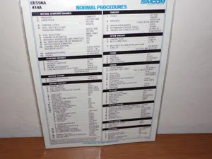

Parts listed for sale by vetted eBay sellers — confirmed on eBay at checkout.