Pilot's Operating Handbook
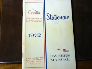
CESSNA U206F STATIONAIR · Pilot's Operating Handbook
Overview
This document serves as the Pilot's Operating Handbook (POH) for the Cessna U206F Stationair, providing essential information for pilots operating this aircraft. It includes detailed specifications, performance data, and operational procedures necessary for safe and efficient flight. The handbook is designed to assist pilots in understanding the aircraft's systems, limitations, and handling characteristics, ensuring compliance with safety regulations and enhancing flight proficiency.
- Wingspan: 36 ft 0 in
- Maximum Takeoff Weight: 3,600 lbs
- Fuel Capacity: 60 gallons
- Stall Speed (Clean): 60 knots
- Maximum Crosswind Component: 15 knots
Document
Source
Originally published by ninelima.org. Sprinkle hosts a reference copy with an added summary, specifications and searchable full text.
Document details
- Type
- Pilot's Operating Handbook
- Pages
- 46
- File size
- 3.2 MB
- Publisher
- ninelima.org
Specifications & performance
Extracted from this document.
Specifications
- Engine (hp)
- 300
- Height (ft)
- 8.833
- Length (ft)
- 28.833
- Wingspan (ft)
- 36
- Engine model
- Continental IO-550-U
- Empty weight (lb)
- 1,680
- Fuel capacity (gal)
- 60
- Max takeoff weight (lb)
- 3,600
Performance
- Landing distance (ft)
- 1,200
- Takeoff distance (ft)
- 1,500
Weight & balance
- Useful load (lb)
- 1,920
- Max ramp weight (lb)
- 3,600
- Baggage allowance (lb)
- 200
- Basic empty weight (lb)
- 1,680
- Max landing weight (lb)
- 3,600
- Max takeoff weight (lb)
- 3,600
Common. Rarer than 3% of the aircraft models we track.
Most owners only have the POH. Here's the essential set for the CESSNA U206F STATIONAIR.
- Pilot's Operating Handbook / AFM
- Checklist
- Maintenance Manual
- Parts Catalog (IPC)
- Systems & Wiring
- Service Bulletins
- Type Certificate (TCDS)
CESSNA U206F STATIONAIR for sale now

Free — save the U206F Stationair to your watchlist and track it in one place.
More CESSNA U206F STATIONAIRmanuals & documents
See all 16 →- ATSB – AO-2024-049Other Documents
- Cessna 206 Aircraft Systems - FAA SafetyTraining Manual
- Cessna 206 Series | Type Acceptance Report - CAAOther Documents
- CESSNA’S TURBO STATIONAIRFlight Manual
- TURBO STATIONAIR HDPerformance Data
- The Cessna 205/206/207Other Documents
- Takeoffs, Approaches, and Landings for the Cessna 172, 182 and 206Weight And Balance
- AAIB Bulletin: 11/2005 G-BGED EW/C2004/06/02Other Documents
- Cessna U206F Stationair, G-STAT - GOV.UKService Bulletins
- Cessna U206F Stationair, G-BAGVMaintenance Manual
- Model 206 & T206 Series Service ManualChecklist
- Cessna Stationair Series, Skywagon 206 Series, and Super Skylane Series Service ManualMaintenance Manual
If you fly the CESSNA U206F STATIONAIR, you may also be researching these.


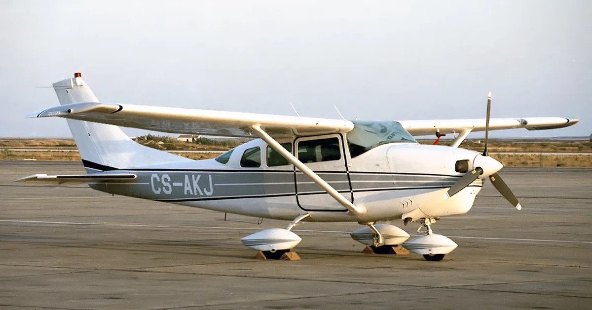


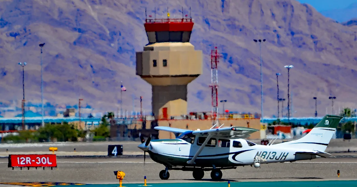
In this document
Aircraft Specifications
The Cessna U206F Stationair features a wingspan of 36 feet, 0 inches, a length of 28 feet, 10 inches, and a height of 8 feet, 10 inches. The empty weight is approximately 1,680 lbs, while the maximum takeoff weight is 3,600 lbs. The fuel capacity is 60 gallons, and the aircraft is powered by a Continental IO-550-U engine with 300 horsepower.
Performance Data
The performance section outlines critical flight parameters, including a takeoff distance of 1,500 feet and a landing distance of 1,200 feet over a 50-foot obstacle. The stall speed in a clean configuration is 60 knots, while the landing stall speed is 55 knots. The best glide speed is 75 knots, and the maximum crosswind component is 15 knots.
Weight and Balance
The basic empty weight of the Cessna U206F Stationair is 1,680 lbs, with a maximum ramp weight of 3,600 lbs and a maximum landing weight of 3,600 lbs. The useful load is 1,920 lbs, and the baggage allowance is 200 lbs. The center of gravity (CG) range is from 34 to 40 inches.
Safety notes
- Ensure weight and balance calculations are completed before flight.
- Adhere to the maximum crosswind limits during takeoff and landing.
Full document text
Cessna (2) SALES AND SERVICE ORE PEOPLE BUY AND Y CESSNA AIRPLANES AN ANY OTHER MAKE 6961 TURBO SKYWAGON 206 ORLD'S LARGEST PRO CER OF GENERAL VIATION AIRCRAFT, SINCE 1956 OWNER'S MANUAL ; PERFORMANCE -SPECIFICATIONS Turbo Skywagon 206 * Top Speed at 19,000 ft GROSS WEIGHT. SPEED, BEST POWER MIXTURE: Cruise, 75% Power at 24,000 ft Cruise, 75% Power at 10,000 ft RANGE, NORMAL LEAN MIXTURE: Cruise, 75% Power at 24,000 ft 63 Gallons, No Reserve. Cruise, 75% Power at 10,000 ft 63 Gallons, No Reserve Cruise, 75% Power at 24,000 ft 80 Gallons, No Reserve Cruise, 75% Power at 10,000 ft. 80 Gallons, No Reserve Optimum Range at 15,000 ft. 63 Gallons, No Reserve 63 Gallons, No Reserve. Optimum Range at 15,000 ft 80 Gallons, No Reserve Optimum Range at 10,000 ft. 80 Gallons, No Reserve 174 mph 910 mi 3600 lbs 2600 lbs 200 mph 206 mph 184 mph 194 mph 170 mph 176 mph 700 mi 740 mi 3.8 hrs 182 mph 645 mi 3.8 hrs 3.8 hrs 192 mph 670 mi 3.8 hrs 168 mph 890 mi 4.9 hrs 174 mph 940 mi 4.9 hrs 182 mph 820 mi 192 mph 850 mi 4.9 hrs 4.9 hrs 168 mph 825 mi 5.9 hrs 139 mph 6.2 hrs 147 mph Optimum Range at 10,000 ft. 750 mi 880 mi 5. 8 hrs 6.4 hrs 129 mph 138 mph 1050 mi 1150 mi 7.6 hrs 7.9 hrs 139 mph 147 mph. 950 mi 1115 mi 7.4 hrs 8.1 hrs 129 mph 138 mph 1030 fpm 26, 300 ft 910 ft 400 ft Total Distance Over 50-foot Obstacle. 1810 ft 760 ft 735 ft 735 ft Total Distance Over 50-foot Obstacle 1395 ft EMPTY WEIGHT (Approximate) 1840 lbs 1760 lbs 760 lbs USEFUL LOAD WING LOADING: Pounds/Sq Foot 20.5 12.6 14.8 9.1 65 gal. 65 gal. 84 gal. 84 gal. 13 qts 13 qts 82 inches 82 inches TSIO-520-C RATE OF CLIMB AT SEA LEVEL SERVICE CEILING. TAKE-OFF: Ground Run LANDING: Landing Roll . . . POWER LOADING: Pounds/HP FUEL CAPACITY: Total Standard Tanks. Optional Long Range Tanks OIL CAPACITY: Total. PROPELLER: 2-Bladed Constant Speed (Dia) ENGINE: 1660 fpm 30, 800 ft 1395 ft 1840 lbs Continental Turbocharged Fuel Injection Engine TSIO-520-C 285 rated BHP at 2700 RPM and 32.5".MP NOTE: Speed performance data is shown for an airplane equipped with optional speed fairings, which increase the speed by one MPH. Performance with an optional 3-bladed propeller is essentially the same as above. * This manual covers operation of the Turbo Skywagon 206 which is certificated as Model TU206D under FAA Type Certificate No. A4CE. CONGRATULATIONS . Welcome to the ranks of Cessna Owners! Your Cessna has been designed and constructed to give you the most in performance, economy, and com- fort. It is our desire that you will find flying it, either for business or pleasure, a pleasant and profitable experience. This Owner's Manual has been prepared as a guide to help you get the most pleasure and utility from your Turbo Skywagon 206. It contains information about your Cessna's equipment, operating procedures, and performance; and suggestions for its servicing and care. We urge you to read it from cover to cover, and to refer to it frequently. Our interest in your flying pleasure has not ceased with your purchase of a Cessna. World-wide, the Cessna Dealer Organization backed by the Cessna Service Department stands ready to serve you. The following services are offered by most Cessna Dealers: FACTORY TRAINED PERSONNEL to provide you with courteous expert service. FACTORY APPROVED SERVICE EQUIPMENT to provide you with the most efficient and accurate workmanship possible. A STOCK OF GENUINE CESSNA SERVICE PARTS on hand when you need them. THE LATEST AUTHORITATIVE INFORMATION FOR SERV- ICING CESSNA AIRPLANES, since Cessna Dealers have all of the Service Manuals and Parts Catalogs, kept current by Service Letters and Service News Letters, published by Cessna Aircraft Company. We urge all Cessna owners to use the Cessna Dealer Organization to the fullest. A current Cessna Dealer Directory accompanies your new airplane. The Directory is revised frequently, and a current copy can be obtained from your Cessna Dealer. Make your Directory one of your cross-country flight planning aids; a warm welcome awaits you at every Cessna Dealer. D686-13 (RGI-100-11/00) ii * (A)9-72" MAX * (B) 9'-6"MAX "A" designates maximum height of airplane with nose strut fully depressed, and 5.00 × 5 nose gear tire and 6.00-× 6 main gear tires installed. "B" designates maximum height of airplane with nose strut fully depressed, and 6.00 × 6 nose gear tire and.8.00 × 6 main gear' tires installed. (A)5°23' (B) 5°58' PRINCIPAL DIMENSIONS D 36'-7'' 8'-13** 6'-10" 28' TABLE OF CONTENTS SECTION I - SECTION II Page= OPERATING CHECK LIST .... 1-1 DESCRIPTION AND OPERATING DETAILS 2-1 SECTION III OPERATING LIMITATIONS............. 3-1 SECTION IV - CARE OF THE AIRPLANE OWNER FOLLOW-UP SYSTEM 4-1 _ .... 4-11 SECTION V - OPERATIONAL DATA. 5-1 SECTION VI- OPTIONAL SYSTEMS. ...................... 6-1 ALPHABETICAL INDEX Index-l iii iv Section I OPERATING CHECK LIST EXTERIOR INSPECTION Turn on master switch and check fuel quan- tity indicators, then turn master switch "OFF." Check ignition switch "OFF." Check that fuel tank selector valve handle is 1 a. b. c. on fullest tank. d. Remove control wheel lock. d. e. Check oxygen supply pressure. f. Check that oxygen masks are available. 4 a. a. Remove rudder gust lock, if installed. b. b. Disconnect tail tie-down. a. Disconnect wing tie-down. c. b. c. Check fuel tank vent opening for stoppage. Check cargo doors securely latched and d. locked (right side only). If cargo load will not permit access to the front cargo door inside handle, lock the door from the outside. by means of the T-handle stored in the map compartment. IMPORTANT The cargo doors must be fully closed and latched before operating the electric wing flaps. A switch in the upper door sill of the front cargo door interrupts the wing flap electrical circuit when the front door is opened or removed, thus preventing the flaps being lowered with possible dam- age to the cargo door or wing flaps when the cargo door is open. If operating with e. f. g. 5 a. Figure 1-1. NOTE
Show full textShow less
Visually check fuel filler caps, inspection plates, and general aircraft condition during walk- around inspection. If night flight is planned, check operation of all lights, and make. sure a flashlight is available. the cargo doors removed and the optional spoiler kit installed, check that the wing flap interrupt switch cover plate is in- stalled so that the wing flaps can be lowered in flight. Check main wheel tire for proper inflation. Inspect airspeed static source holes on sides of fuselage for stoppage. Check propeller and spinner for nicks and security, and propeller for oil leaks. Check engine induction air inlet and cabin heating air inlet for restrictions. Check nose wheel strut and tire for proper inflation. Disconnect nose tie-down. Check oil level. Do not operate with less than nine quarts. Fill for extended flight. Before first flight of day and after each refueling, pull out strainer drain knob for about four seconds to clear fuel strainer of possible water and sediment. Check strainer drain closed. If water is observed, there is a possibility that the fuel tank sumps contain water. Thus, the fuel tank sump drain plugs and fuel reservoir drain plugs should be re- moved to check for the presence of water. Remove pitot tube cover, if installed, and check pitot tube opening for stoppage. Same as One of the first steps in obtaining the utmost performance, service, and flying enjoyment from your Cessna is to familiarize yourself with your airplane's equipment, systems, and controls. This can best be done by reviewing this equipment while sitting in the airplane. Those items whose function and operation are not obvious are covered in Section II. Section I lists, in Pilot's Check List form, the steps necessary to operate your airplane efficiently and safely. It is not a check list in its true form as it is considerably longer, but it does cover briefly all of the points that you should know for a typical flight. The flight and operational characteristics of your airplane are normal in all respects. There are no "unconventional" characteristics or opera- tions that need to be mastered. All controls respond in the normal way within the entire range of operation. All airspeeds mentioned in Sections I and II are indicated air speeds. Corresponding calibrated airspeeds may be obtained from the Airspeed Correction Table in Section V. BEFORE ENTERING THE AIRPLANE. (1) Make an exterior inspection in accordance with figure 1-1. BEFORE STARTING THE ENGINE. (1) Seats and Seat Belts Adjust and lock. (2) Brakes Test and set. (3) Master Switch "ON." (4) Cowl Flaps "OPEN." (Move lever out of locking hole to reposition.) -- (5) Fuel Selector Fullest tank. (6) Turn all radio switches "OFF." 1-1 STARTING ENGINE. -- (1) Mixture Full Rich. (2) Propeller (3) Throttle -- High RPM. Closed. (4) Auxiliary Fuel Pump Switch -- NOTE On "LO." The auxiliary fuel pump will not operate until the igni - tion switch is turned to the "START" position. (5) Ignition Key "START."!. (6) Slowly advance throttle. (7) Release ignition key when engine starts. NOTE If engine fails to continue running, start again from step (3) or use "HI" position of auxiliary fuel pump momentarily to clear vapor from lines. (8) Reset throttle to desired idle speed. '(9) Auxiliary Fuel Pump Switch Off. TAKE-OFF. NORMAL TAKE-OFF. -- (1) Wing Flaps 0° to 20°. Power Full throttle and 2700 RPM. (3) Elevator Control (4) Climb Speed -- -- Lift nose wheel at 60 MPH. 90 to 100 MPH until all obstacles are cleared, then set up climb speed as shown in "NORMAL CLIMB" check list. (5) Wing Flaps Retract (if extended) after obstacles are cleared. MAXIMUM -- PERFORMANCE TAKE-OFF. (1) Wing Flaps 20°. (2) Brakes (3) Power (4) Brakes -- -- -- Apply. Full throttle, 2700 RPM and 28 gal/hr fuel flow. Release. (5) Elevator Control -- Maintain slightly tail-low attitude. (6) Climb Speed 78 MPH until all obstacles are cleared, then set -- up climb speed as shown in "MAXIMUM PERFORMANCE CLIMB" check list. (7) Wing Flaps is reached). Retract (after obstacles are cleared and 90 MPH NOTE Do not reduce power until wing flaps have been retracted. BEFORE TAKE-OFF. 1-2 (1) Parking Brake -- -- Set. (2) Cowl Flaps Check full "OPEN." (3) (4) Flight Controls Check for free and correct movement. Elevator and Rudder Trim "TAKE-OFF" setting. Throttle Setting 1700 RPM. -- -- -- (6) Magnetos Check (50 RPM maximum differential between magnetos). (7) Propeller (full in). -- # CLIMB. NORMAL CLIMB. Cycle from high to low RPM; return to high RPM (3) Mixture (4) Cowl Flaps -- -- Check. (8) Engine Instruments (9) Ammeter 1― (10) Suction Gage Check. -- Check (4.6 to 5.4 inches of mercury). (11) Flight Instruments and Radios -- Set. (12) Optional Autopilot or Wing Leveler (13) Cabin Doors and Window -- "OFF." Closed and locked. (1) Airspeed -- 110 to 120 MPH. (2) Power 27.5 inches and 2500 RPM. Lean to 20.0 gal/hr fuel flow. Open as required. MAXIMUM PERFORMANCE CLIMB-SEA LEVEL TO 19,000 FEET. (1) Airspeed -- (2) Power Mixture 105 MPH. Full throttle and 2700 RPM. - Adjust to 28 gal/hr fuel flow. 1-3 "OPEN." Retract. NOTE See power and fuel flow placard for maximum manifold pressure and fuel flow above 19,000 feet. (4) Cowl Flaps Full "OPEN." -1 AFTER LANDING. (1) Cowl Flaps (2) Wing Flaps -- -- CRUISING. (1) Power -- 15-27.5 inches of manifold pressure and 2200-2500 RPM. Select combination to give no more than 75% power. (2) Cowl Flaps Open as required. (3) Elevator and Rudder Trim Adjust. -- -- (4) Mixture Lean for cruise fuel flow as determined from your Cessna Power Computer or the OPERATIONAL DATA in Section V. LET-DOWN. (1) Power As desired. -- (2) Mixture Lean for smoothness in power descents. rich mixture for idle power. -- (3) Cowl Flaps "CLOSED. BEFORE LANDING. " (1) Fuel Selector Fullest tank. (2) Mixture -- Rich. (3) Propeller -- High RPM. Use full (4) Wing Flaps Down 0°-10° (below 160 MPH), 10°-40° (below 110 MPH). -- (5) Airspeed 85-95 MPH (flaps retracted), 75-85 MPH (flaps extended). (6) Elevator Trim - Adjust for landing. -- NORMAL LANDING. 1-4 (1) Landing Technique- Conventional for all flap settings. SECURE AIRCRAFT. (1) Mixture Idle cut-off. (2) All Switches Off. Brakes (4) Control Lock (3) -- Set. -- Installed. 1-5 INSTRUMENT PANEL + 1 2 3 4 5 6 7 8 9 10 11 12 00000000 0193 07935 Section II DESCRIPTION AND OPERATING DETAILS The following paragraphs describe the systems and equipment whose function and operation is not obvious when sitting in the airplane. This section also covers in somewhat greater detail some of the items listed in Check List form in Section I that require further explanation. 36 35 34 33 32 31 30 29 18 17 16 15 14 13 28 19 27' 222222 11 12 222 20 21 26 25 24 23 1. Marker Beacon Indicator Lights 18. Wing Flap Switch and Switches (Opt.) 19. Mixture Control Knob 2. Flight Instrument Group 20. Propeller Control Knob 3. Radios (Opt.) 21. Cowl Flap Control Handle 4. Radio Selector Switches (Opt.) 22. Engine Primer (Opt.) 5. Rear View Mirror (Opt.) 23. Fuel Selector Valve Handle 6. Manifold Pressure/Fuel Flow Indicator 24. Microphone 7. Fuel Quantity Indicators 25. Electric Elevator Trim and Ammeter Circuit Breaker Switch (Opt.) 8. Cylinder Head Temperature, Oil 26. Rudder Trim Control Wheel Temperature and Pressure Gages 27. Elevator Trim Control Wheel 9. Tachometer 28. Throttle 10. Economy Mixture Indicator (Opt.) 29. Autopilot Control Unit (Opt.) 11. Flight Hour Recorder (Opt.) 30. Microphone Jack 12. Optional Instrument Space 31. Circuit Breakers 13. Radio (Opt.) 32. Parking Brake Handle 14. Map Compartment 33. 34. 15. 16. 17. Cabin Air and Heat Controls Stowable Rudder Pedal Control (Opt.) Cigar Lighter Figure 2-1. Electrical Switches Ignition/Starter Switch 35. Auxiliary Fuel Pump Switch 36. Master Switch FUEL SYSTEM. Fuel is supplied to the engine from two tanks, one in each wing. Usable fuel in each tank, for all flight conditions, is 31.5 gallons for standard tanks and 40 gallons for long range tanks. NOTE Unusable fuel is at a minimum due to the design of the fuel system. However, with 1/4 tank or less, prolonged unco- ordinated flight such as slips or skids can uncover the fuel tank outlets, causing fuel starvation and engine stoppage. Therefore, with low fuel reserves, do not allow the air- plane to remain in uncoordinated flight for periods in ex- cess of one minute. Fuel from each wing tank flows through a fuel reservoir tank to the fuel selector valve. Depending upon the setting of the selector valve, fuel from the left or right tank flows through a fuel strainer and by-pass in the electric auxiliary fuel pump (when it is not operating) to the en- gine-driven fuel pump. From here fuel is distributed to the engine cyl- inders via a fuel control unit and manifold. NOTE Fuel cannot be used from both fuel tanks simultaneously. Vapor and excess fuel from the engine-driven fuel pump and fuel control unit are returned by way of the selector valve to the reservoir tank of the wing tank system being used. 1-6 2-1 2-2 VENT LEFT FUEL TANK FUEL FUEL RESERVOIR TANKS SELECTOR VALVE Π Ο FUEL STRAINER AUXILIARY FUEL PUMP CODE FUEL SUPPLY EXCESS FUEL & VAPOR RETURN VENT RIGHT FUEL TANK CHECK VALVE (FUEL RETURN) OH LO FUEL PUMP VENT THROTTLE AUXILIARY FUEL PUMP SWITCH. The right half of the auxiliary fuel pump switch, labeled "LO," is used for starting. With the switch in the "LO" position, and the ignition- starter switch turned to "START," the auxiliary fuel pump will operate at a low flow rate (providing proper fuel mixture for starting) as the engine is being turned over with the starter. NOTE The auxiliary fuel pump will not operate in the "LO" posi- tion until the ignition switch is turned to "START"" The left half of the switch, labeled "HI," is used for engine operation if the engine-driven pump should fail. When the switch is in this position, the pump operates at one of two flow rates depending upon the setting of the throttle. With the throttle at a cruise setting, the pump is operating at maximum capacity, supplying sufficient fuel flow to maintain flight. When the throttle is moved toward the closed position (as during let-down, landing and taxiing), the auxiliary fuel pump flow rate is automatically reduced, preventing an excessively rich mixture during these periods of reduced engine speed. Operation with the auxiliary fuel pump switch in the "HI" position is also used for fuel vapor control during hot engine starting and high alti- tude climbs in warm temperatures. When the auxiliary fuel pump switch is turned on "HI" during a climb, the fuel flow will increase and the mix- ture should be manually leaned to obtain the desired fuel flow. ENGINE FUEL PUMP FUEL CONTROL UNIT FUEL MANIFOLD FUEL INJECTION NOZZLE FUEL FLOW INDICATOR (Right Half of Dual Instrument) Figure 2-2. NOTE MIXTURE CONTROL FUEL SYSTEM SCHEMATIC If the auxiliary fuel pump switch is accidentally turned on "HI" (with master switch on) with the engine stopped, the intake manifolds will be flooded. To ensure a prompt engine restart in flight after running a fuel tank dry, switch to the tank containing fuel and place the auxiliary fuel pump switch in the "HI" position momentarily (3 to 5 seconds) with the throttle at least 1/2 open. Excessive use of the "HI" position of the auxiliary pump can cause flooding of the engine as indicated by a short (1 to 2 second) period of power followed by a loss of power. This can later be detected by a fuel flow indication accompanied by a lack of power. If flooding does occur, turn off the auxiliary fuel pump switch and normal propeller windmilling should start the engine in 1 to 2 seconds. 2-3 ELECTRICAL SYSTEM MASTER SWITCH SCHEMATIC REGULATOR A+ A+ F ALTERNATOR ALTERNATOR FIELD CIRCUIT BREAKER HO STARTER CONTACTOR CIGAR LIGHTER (WITH CIRCUIT BREAKER) REVERSE POLARITY CONTACTOR ALT LDG LIGHTS PRIMARY BUS NAV -TO STALL WARNING SYSTEM -TO TURN COORDINATOR OR OPTIONAL TURN-AND-BANK INDICATOR TO LANDING AND TAXI LIGHTS TO NAVIGATION LIGHTS AND OPTIONAL CONTROL WHEEL MAP LIGHT LIGHTS TO OIL DILUTION SYSTEM . (OPT) HEAT M AMMETER R GROUND INST SERVICE PLUG- RECEPTACLE (OPT), FLIGHT HOUR RECORDER (OPT) CABIN LIGHTS SPLIT BUS STARTER BATTERY CONTACTOR BATTERY AUXILIARY OIL PRESSURE SWITCH (OPT} CLOCK TO FUEL PUMP CIRCUIT BREAKER THROTTLE SWITCH CONTACTOR (NORMALLY CLOSED) FUEL OFF TO INSTRUMENT CIRCUIT BREAKER FUEL PUMP PUMP SWITCH CODE CIRCUIT BREAKER (AUTO-RESET) O CIRCUIT BREAKER (PUSH-RESET) CIRCUIT BREAKER SWITCH FUSE + DIODE CAPACITOR RESISTOR IGNITION STARTER SWITCH ☑ R MAGNETOS Figure 2-3. ELECTRONIC MUS TO HEATED PITOT AND STALL *WARNING SYSTEM (OPT) FLAP i TO FUEL QUANTITY IND. AND CYL. HEAD TEMP. GAGE TO IGNITION - STARTER *SWITCH TO ELECTRIC ELEVATOR TRIM (OPT) TO INSTRUMENT, RADIO AND GLARE SHIELD MOUNTED LIGHTS TO DOME LIGHTS AND OPTIONAL COURTESY LIGHTS TO ELECTROLUMINESCENT PANELS AND OPTIONAL POST LIGHTING LTO SKYDIVING SIGNAL LIGHTS TO WING FLAP SYSTEM FUEL PUMP TO AUXILIARY FUEL PUMP TO FLASHING BEACON BCN LT TO RADIO (OPT) RADIO 4 TO RADIO (OPT) RADIO 3 ": ③⚫ TO RADIO (OPT) RADIO 2 RADIO 1 AUTO PILOT AUD AMP TO RADIO (OPT} TO AUTOMATIC PILOT (OPT) TO AUDIO AMPLIFIER (OPT)* If the propeller should stop (possible at very low airspeeds) before the tank containing fuel is selected, place the auxiliary fuel pump switch in the "HI" position and advance the throttle promptly until the fuel flow indicator registers approximately 1/2 way into the green arc for 1 to 2 seconds duration. Then retard the throttle, turn off the auxiliary fuel pump, and use the starter to turn the engine over until a start is obtained. ELECTRICAL SYSTEM. Electrical energy is supplied by a 14-volt, direct-current system powered by an engine-driven alternator (see figure 2-3). The 12-volt battery is located on the upper left-hand forward portion of the firewall. Power is supplied to all electrical circuits through a split bus bar, one side containing electronic system circuits and the other side having gen- eral electrical system circuits. Both sides of the bus are on at all times except when either an external power source is connected or the starter switch is turned on; then a power contactor is automatically activated to open the circuit to the electronics bus. Isolating the electronic circuits in this manner prevents harmful transient voltages from damaging the semi-conductors in the electronics equipment. AMMETER. The ammeter indicates the flow of current, in amperes, from the al- ternator to the battery or from the battery to the aircraft electrical system. When the engine is operating and the master switch is "ON," the ammeter indicates the charging rate applied to the battery. In the event the alter- nator is not functioning or the electrical load exceeds the output of the al- ternator, the ammeter indicates the discharge rate of the battery. CIRCUIT BREAKERS AND FUSES. Most of the electrical circuits in the airplane are protected by "push- to-reset" circuit breakers mounted on the left side of the instrument panel. Exceptions to this are the battery contactor closing (external power) cir- cuit which has a fuse mounted near the ground service plug receptacle, and the clock and optional flight hour recorder circuits which have a fuse mounted near the battery. Also, the cigar lighter is protected by a man- ually-reset circuit breaker mounted directly on the back of the light be- hind the instrument panel. Automatically-resetting circuit breakers mounted behind the instrment panel protect the stall warning transmitter 2-4 2-5 and horn circuit, the turn coordinator or optional turn-and-bank-indicator circuit, and the alternator field and wiring circuit. When an optional electric elevator trim system is installed, a circuit breaker switch is mounted on the control pedestal, near the elevator trim control wheel. ELECTROLUMINESCENT LIGHTING. Switches and controls on the lower part of the instrument panel are lighted by electroluminescent panels which do not require light bulbs for illumination. This lighting is controlled by the instrument light rheostat. GLARE SHIELD MOUNTED LIGHTS. Four flush mounted lights are located in the glare shield above the instrument panel, and are covered by red lenses: (When optional post lighting is installed, the light above the radio selector switch panel is changed to a white lens.) The light above the radio selector switch panel is controlled by the radio light rheostat, and the remaining three lights are controlled by the instrument light rheostat when used with console lighting. When post lights are turned on, all of the glare shield lights will turn off except the light above the radio selector switch panel. POST LIGHTS (OPT). The instrument panel may be equipped with optional post lights to further increase night lighting. The post lights are located at the edge of each instrument or control to be lighted, and are controlled by a rocker- type switch labeled "POST-CONSOLE LIGHTS" and the instrument light "POST" rheostat. To operate the post lights, place the switch in the upper position and use the instrument light rheostat to control light intensity. CONTROL WHEEL MAP LIGHT (OPT). A map light may be installed on the bottom of the pilot's control wheel. The light illuminates the lower portion of the cabin just forward of the pilot and is helpful when checking maps and other flight data during night operation. To operate the light, first turn the "NAV LIGHTS" switch on, then adjust the map light's intensity with the knurled rheostat knob located at the bottom of the control wheel. FLASHING BEACON. The flashing beacon should not be used when flying through clouds or overcast; the flashing light reflected from water droplets or particles 2-6 in the atmosphere, particularly at night, can produce vertigo and loss of orientation. CABIN HEATING, VENTILATING AND DEFROSTING SYSTEM. The temperature and volume of airflow into the cabin can be regulated to any degree desired by manipulation of the push-pull "CABIN HEAT" and "CABIN AIR" knobs. When partial cabin heat is desired, blending warm and cold air will result in improved ventilation and heat distribution throughout the cabin. Additional outside air for summer ventilation is provided through the heat and vent system by operation of the push-pull "AUX CABIN AIR" knob. The rotary type "DEFROST" knob regulates the airflow for windshield defrosting. Front cabin heat and ventilating air is supplied by outlet holes spaced across a cabin heat manifold just forward of the pilot's and copilot's feet. Rear cabin heat and air are supplied by two ducts from the manifold, one extending down each side of the cabin to an outlet at the front door post area at floor level. Windshield defrost air is also supplied by a duct leading from the cabin manifold. Separate adjustable ventilators supply additional air; one near each upper corner of the windshield supplies air for the pilot and copilot; and four in the rear cabin ceiling supply air to the rear seat passengers. OXYGEN SYSTEM. An oxygen cylinder, located in the fuselage tailcone, supplies oxygen for the system. Cylinder pressure is reduced to an operating pressure of 70 psi by a pressure regulator attached to the cylinder. A shut-off valve is included as part of the regulator assembly. An oxygen cylinder filler valve is located on the left side of the fuselage tailcone (under a cover plate). Cylinder pressure is indicated by a pressure gage located in the overhead oxygen console above the pilot's and copilot's seats. Six oxygen outlets are provided; two in the overhead oxygen console and four in the cabin ceiling just above the side windows, one at each of the rear seating positions. One permanent, microphone equipped mask is provided for the pilot, and five disposable type masks are provided for 2-7 1800 1600 1400 1200 GAGE PRESSURE - (PSI) 1000 OXYGEN DURATION CHART (76 CUBIC FEET CAPACITY) 800 1850 600 400 200 NOTE: 4 08 08- 2 PILOT PASSENGER PILOT ONLY 6 7 8 9 1 2 3 4 5 OXYGEN DURATION - (HOURS) This chart is based on a pilot with a red color-coded oxygen line fitting and passengers with orange color-coded line fittings. Figure 2-4. the passengers. All masks are the partial rebreathing type, equipped with vinyl plastic hoses and flow indicators. A remote shut-off valve control, located adjacent to the pilot's oxygen outlet in the overhead oxygen console, is used to shut off the sup- ply of oxygen to the system when not in use. The control is mechanically connected to the shut-off valve at the cylinder. With the exception of the shut-off function, the system is completely automatic and requires no manual regulation for change of altitude. The oxygen system (with the continuous flow masks and color-coded lines noted below) is satisfactory for operation to 25,000 feet. Above 25,000 feet, diluter-demand masks are recommended in lieu of the contin- uous flow masks and color-coded lines. OXYGEN SYSTEM OPERATION. Prior to flight, check to be sure that there is an adequate oxygen supply for the trip, by noting the oxygen pressure gage reading. Refer to paragraph OXYGEN DURATION CALCULATION, and to the Oxygen Duration Chart (figure 2-4). Also, check that the face masks and hoses are accessible and in good condition. To use the oxygen system, proceed as follows: NOTE Permit no smoking when using oxygen. (1) Select mask and hose. NOTE The pilot's oxygen hose has a higher flow rate than the passenger hoses; it is color-coded with a red band ad- jacent to the plug-in fitting. Hoses provided for the passengers are color-coded with an orange band. If the aircraft owner prefers, he may provide higher flow rate hoses for all passengers. In any case, it is recommended that the pilot use the larger capacity hose. The pilot's mask is equipped with a microphone to facilitate use of the radio while using oxygen. A switch is incorporated on the left hand control wheel to operate the microphone. (2) Attach mask to face; adjust metallic nose strap for snug mask fit. 2-9 2-8 (3) Select oxygen outlet located nearest to the seat you are occupy- ing and plug delivery hose into it. When the oxygen supply is turned on, oxygen will flow continuously at the proper rate of flow for any altitude without any manual adjustments. (4) Position oxygen supply control knob "ON." (5) Check the flow indicator in the face mask hose. Oxygen is flow- ing if the indicator is being forced toward the mask. (6) Unplug the delivery hose from the outlet coupling when discontin- uing use of oxygen system. This automatically stops the flow of oxygen. (7) Position oxygen supply control knob "OFF." OXYGEN DURATION CALCULATION. The Oxygen Duration Chart (figure 2-4) should be used in determining the usable duration (in hours) of the oxygen supply in your airplane. The following procedure outlines the method of finding the duration from the chart. (1) Note the available oxygen pressure shown on the pressure gage. (2) Locate this pressure on the scale on the left side of the chart, then go across the chart horizontally to the right until you intersect the line representing the number of persons making the flight. After intersecting the line, drop down vertically to the bottom of the chart and read the duration in hours given on the scale. (3) As an example of the above procedure, 1800 psi of pressure will safely sustain the pilot only for 8 hours and 15 minutes. The same pressure will sustain the pilot and three passengers for approximately 2 hours and 50 minutes. NOTE The Oxygen Duration Chart is based on a standard con- figuration oxygen system having one red color-coded hose assembly for the pilot and orange color-coded hoses for the passengers. If red color-coded hoses are pro- vided for pilot and passengers, it will be necessary to compute new oxygen duration figures due to the greater consumption of oxygen with these hoses. This is accom- plished by computing the total duration available to the pilot only (from "PILOT ONLY" line on chart), then di- viding this duration by the number of persons (pilot and passengers) using oxygen. TURBOCHARGED ENGINE SYSTEM. Your aircraft is equipped with a turbocharged engine which makes it possible to maintain 75% cruise power to 24,000 feet. Except for being turbocharged, the engine in your aircraft works and acts just like any normally aspirated engine. However, because the engine is turbocharged, some of the engine characteristics are different. The intent of this section is to point out some of the items that are affect- ed by turbocharging, and outline the correct procedures to be followed so that operation becomes easier and simpler for owners of turbocharged aircraft. For a better understanding of the turbocharged engine system, let's follow the induction air through the engine until it is expelled as exhaust gases. Reference should be made to the schematic of the turbocharger system shown in figure 2-5 as you read through the following steps: (1) Engine induction air is taken in through an opening in the nose cap, ducted through a filter and into the compressor where it is compressed to near sea level pressure. (2) The pressurized induction air then passes through the throttle body and induction manifold into the cylinders. (3) The air and fuel are burned and exhausted to the supercharger turbine. (4) The exhaust gases drive the turbine which, in turn, drives the compressor, thus completing the cycle. At altitudes below 24,000 feet, the turbine has the capability of producing manifold pressures in excess of the maximum allowable 32.5 in. Hg. In order not to exceed 32.5 inches of manifold pressure, a by- pass or waste gate is used so that some of the exhaust will be diverted overboard before it passes through the turbine. It can be seen from studying Steps 1 through 4 that anything that affects the flow of induction air into the compressor or the flow of exhaust gases into the turbine will increase or decrease the speed of the turbo- charger. This resultant change in flow will have no effect on the engine if the waste gate is still open because the waste gate position is changed to hold compressor discharge pressure constant. A waste gate controller automatically maintains maximum allowable compressor discharge pres- sure any time the turbine and compressor are capable of producing that pressure. 2-10 2-11 Turbo-System SCHEMATIC CODE RAM AIR INTAKE AIR FROM COMPRESSOR EXHAUST GAS ENGINE OIL MECHANICAL LINKAGE AIR FILTER D RAM AIR TO MAN. PRESS. PRESS. ALTERNATE AIR DOOR GAGE RELIEF VALVE INTAKE AIR FROM COMPRESSOR EXHAUST GAS OIL ← THROTTLE TO FUEL FLOW GAGE RETURN TO FUEL DISCHARGE NOZZLES TO FUEL PUMP COMPRESSOR TURBINE ENGINE DRIVEN WASTE GATE OIL PUMP WASTE GATE CONTROLLER WASTE GATE ACTUATOR Figure 2-5. EXHAUST OVERBOARD At high altitude, part throttle, or low RPM, the exhaust flow is not capable of turning the turbine and compressor fast enough to maintain maximum compressor discharge pressure, and the waste gate will close to force all of the exhaust flow through the turbine. When the waste gate is fully closed, any change in turbocharger speed will mean a change in engine operation. Thus, any increase or decrease in turbine speed will cause an increase or decrease in manifold pressure and fuel flow. If turbine speed increases, the manifold pressure increases; if the turbine speed decreases, the manifold pressure decreases. Since the compression ratio approaches 3 to 1 at high altitude, any change in exhaust flow to the turbine or ram induction air pressure will be magnified proportionally by the compression ratio and the change in flow through the exhaust system. 2-12 TURBOCHARGED ENGINE OPERATING CHARACTERISTICS. MANIFOLD PRESSURE VARIATION WITH ENGINE RPM. When the waste gate is open, the turbocharged engine will react the same as a normally aspirated engine when the engine RPM is varied. That is, when the RPM is increased, the manifold pressure will decrease slightly. When the engine RPM is decreased, the manifold pressure will increase slightly. However, when the waste gate is closed, manifold pressure variation with engine RPM is just the opposite of the normally aspirated engine. An increase in engine RPM will result in an increase in manifold pressure, and a decrease in engine RPM will result in a decrease in manifold pres- sure. MANIFOLD PRESSURE VARIATION WITH ALTITUDE. At full throttle, your turbocharger is capable of maintaining the max- imum allowable manifold pressure of 32.5 in. Hg to well above 19,000 feet. However, engine operating limitations establish the maximum manifold pressure that may be used. Manifold pressure should be re- duced with the throttle above 19,000 feet, as noted on the operating placard in the airplane (subtract 1 in. Hg from 32.5 for each 1000 feet above 19,000 feet). At part throttle, the turbocharger is capable of maintaining cruise climb power of 2500 RPM and 27.5 in. Hg from sea level to 24,000 feet in standard temperatures, and from sea level to 12,000 feet under hot day conditions without changing the throttle position, once the power setting is established after take-off. Under hot day conditions, this climb power setting is maintained above 12,000 feet by advancing the throttle as neces- sary to maintain 27.5 inches of manifold pressure just as you would a normally aspirated engine during climb. MANIFOLD PRESSURE VARIATION WITH AIRSPEED. When the waste gate is closed, manifold pressure will vary with vari- ations in air speed. This is because the compressor side of your turbo- charger operates at pressure ratios of up to 3 to 1 and any change in pressure at the compressor inlet is magnified at the compressor outlet with a resulting effect on the exhaust flow and turbine side of the turbo- charger. 2-13 FUEL FLOW VARIATIONS WITH CHANGES IN MANIFOLD PRESSURE. The engine-driven fuel pump output is regulated by engine speed and compressor discharge pressure. Engine fuel flow is regulated by fuel pump output and the metering effects of the throttle and mixture con- trol. When the waste gate is open, fuel flow will vary directly with mani- fold pressure, engine speed, mixture, or throttle control position. In this case, manifold pressure is controlled by throttle position and the waste gate controller, while fuel flow varies with throttle movement and manifold pressure. When the waste gate is closed and manifold pressure changes are due to turbocharger output, as discussed previously, fuel flow will follow manifold pressure even though the throttle position is unchanged. This means that fuel flow adjustments required of the pilot are minimized to (1) small initial adjustments on take-off or climb-out for the proper rich climb setting, (2) lean-out in cruise to the recommended normal lean cruise setting, and (3) return to full rich position for approach and landing. MANIFOLD PRESSURE VARIATION WITH INCREASING OR DECREASING FUEL FLOW. When the waste gate is open, movement of the mixture control has little or no effect on the manifold pressure of the turbocharged engine. When the waste gate is closed, any change in fuel flow to the engine will have a corresponding change in manifold pressure. That is, increas- ing the fuel flow will increase the manifold pressure and decreasing the fuel flow will decrease the manifold pressure. This is because an in- creased fuel flow to the engine increases the mass flow of the exhaust. This turns the turbocharger faster, increasing the induction air flow and raising the manifold pressure. MOMENTARY OVERSHOOT OF MANIFOLD PRESSURE. Under some circumstances (such as rapid throttle movement, es- pecially with cold oil) it is possible that the engine can be overboosted slightly above the maximum allowable manifold pressure of 32.5 inches. This would most likely be experienced during the take-off roll or during a change to full throttle operation in flight. The induction air pressure relief valve will normally limit the overboost to 2 to 3 inches. A slight overboost of 2 to 3 inches of manifold pressure is not consi- dered detrimental to the engine as long as it is momentary. No corrective 2-14 action is required when momentary overboost corrects itself and is fol- lowed by normal engine operation. However, if overboosting of this nature persists when oil temperature is normal or if the amount of overboost tends to exceed 3 inches or more, the throttle should be retarded to elimi- nate the overboost and the controller system, including the waste gate and relief valve, should be checked for necessary adjustment or replacement of components. ALTITUDE OPERATION. Because your turbocharged aircraft will climb faster and higher than a normally aspirated aircraft, fuel vaporization may be encountered. When fuel flow variations of ± 1 gal/hr or more are observed (as a "nervous" fuel flow needle), turning the auxiliary fuel pump on "HI" will control vapor. However, it will also increase fuel flow, making it neces- sary to adjust the mixture control for the desired fuel flow. The auxil- iary fuel pump should be left on for the remainder of the climb. It can be turned off whenever fuel flow will remain steady with it off, and the mixture must be adjusted accordingly. HIGH ALTITUDE ENGINE ACCELERATION. Your engine will accelerate normally from idle to full throttle with full rich mixture at any altitude below 20,000 feet. At higher altitudes, it is usually necessary to lean the mixture to get smooth engine acceler- ation from idle to maximum power. At altitudes above 25,000 feet, and with temperatures above standard, it takes one to two minutes for the turbine to accelerate from idle to maximum RPM although adequate power is available in 20 to 30 seconds. STARTING ENGINE. Proper fuel management and throttle adjustments are the determining factors in securing an easy start from your turbocharged continuous-flow fuel-injection engine. The procedure outlined in Section I should be fol- lowed closely as it is effective under nearly all operating conditions. Conventional full rich mixture and high RPM propeller settings are used for starting; the throttle, however, should be fully closed initially. When ready to start, depress the right half of the auxiliary fuel pump switch to "LO" and turn the ignition-starter switch to "START" position. At the same time the starter engages and turns the engine, the auxiliary fuel pump will operate at a low flow rate, supplying fuel for starting. 2-15 While cranking, slowly advance the throttle until the engine starts. Slow throttle advancement is essential since the engine will start readily when the correct fuel/air ratio is obtained. On the other hand, fast throttle movement may prevent starting since an excessively rich mixture will be obtained due to greater fuel flow metered by the throttle position. In this case, another starting attempt must be made. When the engine has started, reset the throttle to the desired idle speed and turn the fuel pump switch off. When the engine is hot or the outside air temperatures are high, the engine may die after running several seconds because the mixture became either too lean due to fuel vapor or too rich due to excessive prime fuel. The following procedure will prevent over-priming and take care of fuel vapor in the system: (1) Set the throttle 1/3 to 1/2 open. (2) When the ignition key is on "BOTH" and you are ready to engage the starter, turn the fuel pump on "HI" until the fuel flow comes up to 4-6 gal/hr and then turn the pump off. NOTE During a restart after a brief shut-down in extremely hot weather, the presence of fuel vapor may require the pump to run on "HI" for up to 1 minute or more before the vapor is cleared sufficiently to obtain 4-6 gal/hr for starting. : (3) Without hesitation, engage the starter and the engine should start in 3 to 5 revolutions. Adjust the throttle for 1200-1400 RPM. (4) If there is fuel vapor in the lines, it will pass into the injector nozzles in 2 to 3 seconds and the engine will gradually slow down and stop. When engine speed starts to decrease, turn the fuel pump on "HI" for approximately one second to clear out the vapor. Inter- mittent use of "HI" boost is needed since prolonged use of "HI" pump after the vapor is cleared will flood out the engine. (5) Let the engine run at 1200 to 1400 RPM until the vapor is elim- inated and the engine idles normally. If prolonged cranking is necessary, allow the starter motor to cool at frequent intervals, since excessive heat may damage the armature. TAXIING. 2-16 Taxiing over loose gravel or cinders should be done at low engine TAXIING DIAGRAM USE UP AILERON ON LH WING AND NEUTRAL ELEVATOR USE UP AILERON ON RH WING AND NEUTRAL ELEVATOR USE DOWN AILERON ON LH WING AND DOWN ELEVATOR USE DOWN AILERON ON RH WING AND DOWN ELEVATOR CODE WIND DIRECTION NOTE Strong quartering tail winds require caution. Avoid sudden bursts of the throttle and sharp braking when the airplane is in this attitude. Use the steerable nose wheel and rudder to maintain direction. Figure 2-6. 2-17
849 CESSNA U206F STATIONAIR parts for sale
See all →




Parts listed for sale by vetted eBay sellers — confirmed on eBay at checkout.