Service Bulletin
Cirrus SR20 · Service Bulletins
Overview
This Service Bulletin (SB 2X-34-24 R1) provides instructions for the optional upgrade of GPS systems in Cirrus SR20 and SR22 aircraft equipped with Avidyne Entegra Primary Flight Displays. It details the installation of a WAAS kit, which includes the installation of WAAS antennas and GPS Navigator hardware upgrades. The bulletin is applicable to specific serial numbers of both aircraft models and outlines the necessary compliance steps, parts required, and estimated man-hours for installation. The bulletin emphasizes that compliance is optional and provides guidance for ensuring proper installation and functionality of the upgraded systems.
- This Service Bulletin applies to Cirrus SR20 serial numbers 1337-1877 and SR22 serial numbers 0435-2749.
- Installation of the WAAS kit is optional but recommended for improved GPS functionality.
- Estimated man-hours for installation range from 11 to 46 hours depending on the kit and aircraft configuration.
- PFD software must be at least version 6.2.2 for compliance with this bulletin.
- Specific parts and kits are required for different serial numbers and configurations.
Document
Source
Originally published by airwork.biz. Sprinkle hosts a reference copy with an added summary, specifications and searchable full text.
Document details
- Type
- Service Bulletins
- Year
- 2008
- Pages
- 43
- File size
- 1.5 MB
- Publisher
- airwork.biz
Common. One of the most common aircraft types we track.
Most owners only have the POH. Here's the essential set for the Cirrus SR20.
- Pilot's Operating Handbook / AFM
- Checklist
- Maintenance Manual
- Parts Catalog (IPC)
- Systems & Wiring
- Service Bulletins
- Type Certificate (TCDS)
Cirrus SR20 for sale now



Free — save the SR20 to your watchlist and track it in one place.
More Cirrus SR20manuals & documents
See all 17 →- DFC Autopilot Series Installation ManualWiring Diagram
- Cirrus Owners and Pilots Quick Reference Guide for SR Series aircraftV Speeds Reference
- Validation ReportOther Documents
- PILOT’S OPERATING HANDBOOK AND FAA APPROVED AIRPLANE FLIGHT MANUAL for the CIRRUS DESIGN SR20Pilot's Operating Handbook
- Standard Practice Maintenance ManualMaintenance Manual
- Aviation Maintenance Alert - Cirrus SR20 and SR22 AircraftMaintenance Manual
- PILOT’S OPERATING HANDBOOK AND FAA APPROVED AIRPLANE FLIGHT MANUAL for the CIRRUS SR20Training Manual
- CIRRUS SR20 NORMAL CHECKLISTEmergency Procedures
- Dual Fuel Level – Cirrus Aircraft w/ CIES Inc. SendersWiring Diagram
- Pilot’s Operating HandbookPilot's Operating Handbook
- AIRWORTHINESS DIRECTIVEAirworthiness Directives
- SERVICE BULLETIN SB 7084Service Bulletins
If you fly the Cirrus SR20, you may also be researching these.


In this document
Compliance
Accomplishment of this Service Bulletin is optional for owners. It provides an upgrade for GPS1 or GPS1/GPS2 systems.
Effectivity
This bulletin applies to Cirrus SR20 serial numbers 1337 through 1877 and Cirrus SR22 serial numbers 0435 through 2749, both equipped with Avidyne Entegra Primary Flight Displays.
Purpose
The purpose of this Service Bulletin is to inform owners of an optional WAAS kit and facilitate its installation.
Description
The bulletin contains instructions for WAAS antenna installation, GPS Navigator hardware upgrades, and PFD software upgrades.
Manpower Requirements
The estimated man-hours for installation vary by kit: Kit 70190-001 requires 11.0 hours, while Kit 70190-002 requires 18.0 hours for certain serials.
Accomplishment Instructions
Instructions are provided for upgrading GPS systems, including antenna installation and software upgrades. Specific serial numbers have different requirements for compliance.
Material Information
Parts required for compliance can be obtained from authorized Cirrus Design Service Centers. Specific kits and part numbers are listed for different aircraft configurations.
Safety notes
- Using existing GPS antenna locations may result in loss of WAAS reception under certain conditions.
- Ensure hands are clean when working with headliners and trim pieces.
Full document text
SB 2X-34-24 R1 1 of 41 Cirrus Design Corporation 4515 Taylor Circle Duluth, Minnesota 55811 PH (218) 788-3000 Cirrus Design Corporation cannot be responsible for the quality of work performed by others while fulfilling the requirements of this service bulletin. Procedures specified in this service bulletin must be accomplished using industry standard maintenance practices and applicable government regulations. Service Bulletin COMPLIANCE Optional: Accomplishment of this Service Bulletin is at the owner’s option. This Service Bulletin was revised to provide for the optional upgrade of GPS1 or GPS1/GPS2. EFFECTIVITY Cirrus Design SR20 serial numbers 1337 thru 1877 w/ Avidyne Entegra Primary Flight Display. Cirrus Design SR22 serial numbers 0435 thru 2749 w/ Avidyne Entegra Primary Flight Display. APPROVAL FAA approval has been obtained on all technical data in this Service Bulletin that affects type design. PURPOSE The purpose of this Service Bulletin is to inform SR20 and SR22 owners of an optional WAAS kit and to facilitate installation of the WAAS kit. DESCRIPTION This Service Bulletin contains instructions for WAAS antenna/cable installation, GPS Navigator hardware upgrade(s), and PFD software upgrade. The Garmin GPS Navigator WAAS installation consists of three parts: • Procedures in this Service Bulletin for WAAS antenna(s) installation (including ELT shielding for affected aircraft). • Avidyne PFD software upgrade. Refer to Avidyne Service Bulletin SB 601-00006-081: Release 7 PFD Re-Installation for Service. • Garmin GPS Navigator upgrade. Refer to Garmin STC SA01933LA and Garmin STC Upgrade Installation Manual, PN 190-00357-06 Revision B or later. Serials SR20-1802, 1816 thru 1877, Serials SR22-2578 thru 2749: Aircraft are already equipped with required WAAS hardware. Performance of Inspection/Check- PFD Software Version is the only require- ment for compliance with SB 2X-34-24 R1. Owners and operators with PFD software currently at Avidyne Release 6.2.2 may install this Service Bulle- tin; however, future upgrade to Avidyne Release 7.0 PFD software is required to provide GNS 430W/GNC 420W WAAS approach functionality. Cirrus recommends that Avidyne Release 7.0 PFD software be installed concurrently with this Service Bulletin. ATA 34-50: Dependent Position Determining WAAS Antenna Installation on PFD Equipped Aircraft 23 Oct 2007 SB 2X-34-24 R1 Models SR20 and SR22 Issued: 29 Jan 2008 Revised: SB 2X-34-24 R1 2 of 41 Revised: 29 Jan 2008 CAUTION: Under certain headings and geographic locations, using the existing GPS antenna locations could result in loss-of or weakened WAAS reception. On Cirrus aircraft, the Garmin 400W- Series Navigator requires an external antenna installation. WARRANTY INFORMATION Part and labor costs for this Service Bulletin are at the owner’s expense. MANPOWER REQUIREMENTS Kit 70190-001: 11.0 manhours. Kit 70190-002: 18.0 manhours (Serials SR20-1798 thru 1877, SR22-2438 thru 2749: 18.5 manhours). Kit 70190-001 and Kit 70190-003: 35.0 manhours (Serials w/ EMM repair: 41.0 manhours). Kit 70190-002 and Kit 70190-003: 40.0 manhours (Serials w/ EMM repair: 46.0 manhours). Kit 70190-001 and Kit 70190-004: 14.5 manhours. Kit 70190-002 and Kit 70190-004: 21.0 manhours. OTHER PUBLICATIONS AFFECTED SR20 Airplane Maintenance Manual (p/n 12137-001) SR20 Illustrated Parts Catalog (p/n 12138-001) SR20 Pilot’s Operating Handbook (p/n 11934-003) SR22 Airplane Maintenance Manual (p/n 13773-001) SR22 Illustrated Parts Catalog (p/n 13774-001) SR22 Pilot’s Operating Handbook (p/n 13772-001) WEIGHT AND BALANCE N/A MATERIAL INFORMATION The following parts are required to comply with this Service Bulletin. Parts can be obtained from an Autho- rized Cirrus Design Service Center or Parts Distributor. Serials SR20-1337 thru 1801, 1803 thru 1815, SR22-0435 thru 2577 w/o XM Weather: Order kit 70190- 001 to obtain the following parts. Item No. Description P/N or Spec. Supplier Quantity 1 Antenna, WAAS GPS 12744-004 Cirrus Design 1 3 Cable, GPS1 Antenna 18515-001 Cirrus Design 1 6 Gasket 18513-101 Cirrus Design 1 7 Washer, Flat, Wide Area AN970-3 Cirrus Design 4 9 Nut, Self-locking, Nylon Insert, #8-32, Low Profile MS21083N08 Cirrus Design 4 10 Screw, 100 Deg Countersunk, Self-Sealing, #8-32 × 1.375" 51952-138 Cirrus Design 4 11 Loom, Corrugated, 60" Length, 0.625-inch Dia. 50943-063 Cirrus Design 1 SB 2X-34-24 R1 3 of 41 Revised: 29 Jan 2008 Serials SR20-1337 thru 1801, 1803 thru 1815, SR22-0435 thru 2577 w/ XM Weather: Order kit 70190-002 to obtain the following parts. 13 Tape, Tin Plated Copper, 4", 64" Length 50379-002 Cirrus Design 1 17 SR20 Airplane Flight Manual Supplement 11934-S38 Cirrus Design 1 18 SR22 Airplane Flight Manual Supplement 13772-132 Cirrus Design 1 25 Service Bulletin SB 2X-34-24 R1 Cirrus Design 1 Item No. Description P/N or Spec. Supplier Quantity 2 Antenna, WAAS GPS/XM 12744-005 Cirrus Design 1 3 Cable, GPS1 Antenna 18515-001 Cirrus Design 1 4 Cable, XM Antenna 18516-001 Cirrus Design 1 6 Gasket 18513-101 Cirrus Design 1 7 Washer, Flat, Wide Area AN970-3 Cirrus Design 4 9 Nut, Self-locking, Nylon Insert, #8-32, Low Profile MS21083N08 Cirrus Design 4 10 Screw, 100 Deg Countersunk, Self-Sealing, #8-32 × 1.375" 51952-138 Cirrus Design 4 11 Loom, Corrugated, 60" Length, 0.625-inch Dia. 50943-063 Cirrus Design 1 13 Tape, Tin Plated Copper, 4", 64" Length 50379-002 Cirrus Design 1 16 Precure Patch 70190-201 Cirrus Design 1 17 SR20 Airplane Flight Manual Supplement 11934-S38 Cirrus Design 1 18 SR22 Airplane Flight Manual Supplement 13772-132 Cirrus Design 1 19 Composite Repair Kit • L285 Base Resin, 71.5 g • H287 Curing Agent, 28.5 g • Fumed Silica (Aerosil 200), 1.6 g • Microfiller (Sil-Cell), 2.7 g • 70198-101 (45°), 3.8 × 3.3 inches • 70198-102 (-45°), 5.3 × 4.8 inches • 70198-103 (45°), 6.8 × 6.3 inches 70198-001 Cirrus Design 1
Show full textShow less
25 Service Bulletin SB 2X-34-24 R1 Cirrus Design 1 Item No. Description P/N or Spec. Supplier Quantity SB 2X-34-24 R1 4 of 41 Revised: 29 Jan 2008 Serials SR20-1337 thru 1797, SR22-0435 thru 2420 w/ Garmin GNS 430 or GNC 420 GPS2 requiring fuselage repair: Order kit 70190-003 to obtain the following parts. Note: Serials w/ Garmin GNC 250XL GPS2 or Serials not upgrading GPS2: Kit 70190-003 is not required. Item No. Description P/N or Spec. Supplier Quantity 1 GPS Antenna, WAAS 12744-004 Cirrus Design 1 5 Cable, GPS2 Antenna 18515-002 Cirrus Design 1 6 Gasket 18513-101 Cirrus Design 1 8 Washer, #8 × 0.032" Thick NAS1149FN832P Cirrus Design 4 9 Nut, Self-locking, Nylon Insert, #8-32, Low Profile MS21083N08 Cirrus Design 4 10 Screw, 100 Deg Countersunk, Self-Sealing, #8-32 × 1.375" 51952-138 Cirrus Design 4 12 Loom, Corrugated, 84" Length, 0.5-inch Dia. 50943-050 Cirrus Design 1 14 Cable Anchors 50132-001 Cirrus Design 3 20 Composite Repair Kit • L285 Base Resin, 71.5 g • H287 Curing Agent, 28.5 g • Fumed Silica (Aerosil 200), 1.6 g • Microfiller (Sil-Cell), 2.7 g • 70198-201 (45°), 10.8 × 3.8 inches • 70198-202 (0°), 12.3 × 5.3 inches • 70198-203 (90°), 13.8 × 6.8 inches • 70198-204 (-45°), 15.3 × 8.3 inches 70198-002 Cirrus Design 1 21 Composite Repair Kit • EMM, 28.0 × 6.0 inches 70198-003 Cirrus Design 1 22 Composite Repair Kit • Epon 862, Heloxy 68 Blend 60.0 g • Epicure 3234 Curing Agent, 9.6 g 70198-004 Cirrus Design 2 24 Standoff, Locking, Clickbond #6-32 50757-014 Cirrus Design 2 25 Service Bulletin SB 2X-34-24 R1 Cirrus Design 1 SB 2X-34-24 R1 5 of 41 Revised: 29 Jan 2008 Serials SR20-1798 thru 1801, 1803 thru 1815, SR22-2421 thru 2577 w/ Garmin GNS 430 or GNC 420 GPS2 not requiring fuselage repair: Order kit 70190-004 to obtain the following parts. Note: Serials w/ Garmin GNC 250XL GPS2 or Serials not upgrading GPS2: Kit 70190-004 is not required. Serials w/ 121.5 MHz ELT: Order 18389-001 to obtain the following part. Item No. Description P/N or Spec. Supplier Quantity 1 GPS Antenna, WAAS 12744-004 Cirrus Design 1 5 Cable, GPS2 Antenna 18515-002 Cirrus Design 1 6 Gasket 18513-101 Cirrus Design 1 8 Washer, #8 × 0.032" Thick NAS1149FN832P Cirrus Design 4 9 Nut, Self-locking, Nylon Insert, #8-32, Low Profile MS21083N08 Cirrus Design 4 10 Screw, 100 Deg Countersunk, Self-Sealing, #8-32 × 1.375" 51952-138 Cirrus Design 4 12 Loom, Corrugated, 84" Length, 0.5-inch Dia. 50943-050 Cirrus Design 1 14 Cable Anchors 50132-001 Cirrus Design 3 25 Service Bulletin SB 2X-34-24 R1 Cirrus Design 1 Item No. Description P/N or Spec. Supplier Quantity 26 ELT Shield 18389-001 Cirrus Design 1 SB 2X-34-24 R1 6 of 41 Revised: 29 Jan 2008 ACCOMPLISHMENT INSTRUCTIONS Note: Serials SR20-1337 thru 1801, 1803 thru 1815, Serials SR22-0435 thru 2577: SB 2X-34-24 R1 is comprised of three parts - instructions for WAAS antenna/cable installation, GPS Navigator hardware upgrade(s), and PFD software upgrade. Once modifications are underway, all three parts must be completed prior to the airplane returning to flight. Serials SR20-1802, 1816 thru 1877, Serials SR22-2578 thru 2749: Performance of Inspection/ Check - PFD Software Version is the only requirement for compliance with SB 2X-34-24 R1. A. Perform Procedure - Upgrade Kit Options. Note: If only one GPS antenna (GPS1) is upgraded, the other antenna will continue to function as previously installed; however, loss of crossfill functionality between GPS1 and GPS2 will exist and future updates to the different database cards for each transceiver will require dual maintenance. Serials w/ Garmin GNC 250XL GPS2: Upgrade kit is not available for GPS2. 1. Serials w/o XM Weather: Order kit 70190-001 for GPS1. 2. Serials w/ XM Weather: Order kit 70190-002 for GPS1. Note: Serials w/ existing XM Weather and COM1/XM antenna configuration: Cirrus Design has discontinued use of the COM1/XM antenna. Although the COM1/XM antenna can remain functional in its intended configura- tion, it is preferable that those aircraft be equipped with the WAAS GPS/XM antenna using kit 70190-002 with one of the following configurations: Configuration #1 - COM1/XM antenna replaced by the standalone COM1 antenna or Configuration #2 - COM1/XM antenna used exclusively for COM1 signal transmis- sion If installed, the existing COM1/XM antenna may be retained; however, future equipment options will be based on a standalone COM1 antenna with WAAS GPS/XM antenna configuration. a. To replace COM1/XM antenna (Configuration #1): (1) Acquire necessary tools, equipment, and supplies. (2) At antenna, disconnect COM1 antenna cable from aft antenna connector. (3) At antenna, disconnect right-angle connector on XM antenna cable from forward antenna connector. Note: If attenuator is installed between XM receiver and antenna cable, remove and discard attenuator. (4) At receiver, disconnect antenna cable from antenna connector. Description P/N or Spec. Supplier Purpose COM1 Antenna 12740-001 Cirrus Design Replace antenna. SB 2X-34-24 R1 7 of 41 Revised: 29 Jan 2008 (5) At base of door pillar, remove cable ties securing antenna cable to existing wire loom. (6) Remove any existing cable anchors and cable ties securing XM antenna cable. (7) Remove XM antenna cable from airplane. (8) Remove COM1/XM antenna. (Refer to AMM 34-50) (9) Install COM1 antenna. (Refer to AMM 34-50) b. To disable XM functionality in COM1/XM antenna (Configuration #2): (1) At antenna, disconnect right-angle connector on XM antenna cable from forward antenna connector. Note: If attenuator is installed between XM receiver and antenna cable, remove and discard attenuator. (2) At receiver, disconnect antenna cable from antenna connector. (3) At base of door pillar, remove cable ties securing antenna cable to existing wire loom. (4) Remove any existing cable anchors and cable ties securing XM antenna cable. (5) Remove XM antenna cable from airplane. 3. If completing the GPS2 antenna upgrade, an inspection of the ceiling structure is necessary to determine if repair is required prior to GPS2 installation. The aft RH ceiling foam core edge runs parallel with the bondline at BL0. On earlier aircraft, however, the aft RH ceiling foam core edge exhibits an offset (joggle) that extends inboard. This offset interferes with the GPS2 installation area and requires fuselage repair. (See Figure 07) a. At aft cabin ceiling, locate inboard edge of RH ceiling foam core running parallel with the bondline at BL0. b. If inboard edge of RH ceiling foam core has characteristics of an inboard offset towards the bondline, fuselage repair is required to accommodate GPS2 installation. Order kit 70190-003 for GPS2. c. If inboard edge of RH ceiling foam core runs straight and parallel with bondline, fuselage repair for GPS2 installation is not required. Order kit 70190-004 for GPS2. B. Perform Inspection/Check - PFD Software Version. Avidyne PFD software version must be P/N 530-00183-000 Rev 02 (Release 6.2.2) or later for installa- tion of this Service Bulletin. If PFD software version is P/N 530-00183-000 Rev 02 (Release 6.2.2), this Service Bulletin may be installed; however, future upgrade to P/N 530-00195-000 Rev 00 (Release 7.0) PFD software is required to provide GNS 430W/GNC 420W WAAS functionality. During system startup, PFD software version is displayed on screen. Note existing PFD setup configu- ration. If software upgrade is required, existing PFD setup configuration will be erased and must be re- entered. 1. Set BAT 1 and AVIONICS switches to ON positions. 2. If PFD software version is P/N 530-00195-000 Rev 00 (Release 7.0) or higher, GNS 430W/GNC 420W compatibility is already provided. No PFD software upgrade is required. 3. If PFD software version is P/N 530-00183-000 Rev 02 (Release 6.2.2), GNS 430W/GNC 420W WAAS compatibility is not provided. Although not required for installation of this Service Bulletin, future PFD software upgrade will be required for GNS 430W/GNC 420W WAAS functionality. SB 2X-34-24 R1 8 of 41 Revised: 29 Jan 2008 4. If PFD software version is lower than P/N 530-00183-000 Rev 02 (Release 6.2.2), PFD software must be upgraded to Release 6.2.2 or higher. Upgrade PFD software: a. Contact Avidyne for upgrade instructions. (Refer to www.avidyne.com) b. Remove PFD. (Refer to AMM 31-60) c. Install upgraded PFD. (Refer to AMM 31-60 and Avidyne SB 601-00006-081: Release 7 PFD Re-Installation for Service) d. Perform Functional Test - PFD Setup. (Refer to AMM 31-60) e. Perform Functional Test - Magnetometer Calibration. (Refer to AMM 34-20) f. Perform Functional Test - Flight Guidance Programmer/Computer. (SR20 Serials: Refer to AMM 22-12, SR22 Serials: Refer to AMM 22-11) 5. Serials SR20-1802, 1816 thru 1877, Serials SR22-2578 thru 2749: Aircraft are already equipped with required WAAS hardware. No further action is required. Complete airplane records by not- ing compliance with SB 2X-34-24 R1 in Aircraft Logbook. C. Remove key from ignition. D. Set BAT 1, BAT 2, and AVIONICS switches to OFF positions. E. Remove engine cowling. (Refer to AMM 71-10) F. Disconnect battery. (Refer to AMM 24-30) G. Upgrade GPS Navigator(s). 1. Contact Garmin International for pre-registration and upgrade instructions. Refer to Garmin STC SA01933LA and Garmin STC Upgrade Installation Manual, PN 190-00357-06 Revision B or later. 2. Remove GPS Navigator(s). (Refer to AMM 34-50) 3. Install upgraded 400W-Series GPS Navigator(s). (Refer to AMM 34-50) CAUTION: Ensure hands are clean while working with headliners and trim pieces. H. Remove both cabin seats. (Refer to AMM 25-10) I. Remove glareshield. (Refer to AMM 25-10) J. Kit 70190-003 or Kit 70190-004: Remove RH console panel. (Refer to AMM 25-10) K. Remove RH A-pillar bottom door trim. (Refer to AMM 25-10) L. Kit 70190-002 and Serials SR20-1798 thru 1877, SR22-2438 thru 2749: Remove RH B-pillar top door trim. (Refer to AMM 25-10) M. Kit 70190-002 and Serials SR20-1798 thru 1877, SR22-2438 thru 2749: Remove RH rear cabin side trim. (Refer to AMM 25-10) N. Remove forward headliner. (Refer to AMM 25-10) O. Remove center headliner. (Refer to AMM 25-10) P. Remove MFD. (Refer to AMM 31-60) Q. Remove radio module assembly. (Refer to AMM 25-10) R. Remove GPS antenna(s). Note: If only upgrading GPS1, do not remove antenna or cable for unaffected GPS2 installa- tion. 1. Remove GPS antenna(s). (Refer to AMM 34-40) 2. Remove previously installed reclosable fasteners used to secure GPS antenna(s). 3. Remove residual adhesive and solvent clean GPS installation area(s). (Refer to AMM 20-30) SB 2X-34-24 R1 9 of 41 Revised: 29 Jan 2008 4. Remove tie-downs securing GPS antenna cable(s). 5. Disconnect GPS antenna cables from GPS Navigators. Note: To facilitate removal of GPS antenna cables, it is required to disconnect unrelated cables and lines interfering with removal. Remove cables/lines in order presented. a. At MFD opening and sides of radio rack, locate P550 cables for autopilot. If cables obstruct removal of GPS antenna cables, disconnect and stow P550 cables. Note: If audio panel is not installed at upper configuration above GPS Navigators, it is not necessary to disconnect P521 cable for audio panel. b. Disconnect P521 cable for audio panel. c. Disconnect COM1 antenna cable from GPS #1 transceiver. d. Disconnect COM1 coolant line from GPS #1 transceiver. e. Disconnect GPS1 antenna cable from GPS #1 transceiver. f. Disconnect COM2 coolant line from GPS #2 transceiver. g. Disconnect GPS2 antenna cable from GPS #2 transceiver. 6. Remove and discard existing GPS antenna cable(s) from airplane. S. Kit 70190-003 or Kit 70190-004: Drill GPS2 antenna installation area. (See Figure 08), (See Figure 09) 1. Acquire necessary tools, equipment, and supplies. 2. From COM1 antenna forward installation screws, measure aft 22.20 inches (56.39 cm) and mark. 3. From previous mark, mark perpendicular line intersecting with BL0. 4. From intersection at BL0, measure 0.80 inch (2.03 cm) to the right, and mark forward RH antenna installation hole. 5. From previous mark, measure 3.30 inches (8.38 cm) aft, and mark aft RH antenna installation hole. 6. From previous mark, measure 1.60 inches (4.06 cm) to the left, and mark aft LH antenna instal- lation hole. 7. From previous mark, measure 3.30 inches (8.38 cm) forward, and mark forward LH antenna installation hole. 8. From intersection of forward mounting holes at BL0, measure 1.04 inches (2.64 cm) aft, and mark antenna cable pass-through hole. 9. At antenna cable pass-through hole mark, use 0.25 inch (0.64 cm) drill bit to drill pilot hole. Description P/N or Spec. Supplier Purpose Isopropyl Alcohol TT-I-735 Grade A or B Any Source Clean installation area. Cotton Cloth (clean and lint free) - Any Source Clean installation area. Drill Bit 0.25 inch (0.64 cm) Any Source Drill pilot holes for connector holes. Drill Bit 0.14 inch (0.36 cm) Any Source Drill antenna mounting holes. Hole Saw 0.75 inch (1.91 cm) Any Source Drill connector holes. Deburring Tool - Any Source Deburr. SB 2X-34-24 R1 10 of 41 Revised: 29 Jan 2008 10. At outer laminate, use 0.75 inch (1.91 cm) hole saw to drill antenna cable pass-through hole at pilot hole. 11. At each mounting hole mark, use 0.14 inch (0.36 cm) drill bit to drill mounting holes. 12. Deburr edges of pass-through and mounting holes. 13. Solvent clean installation area at antenna mounting holes with isopropyl alcohol. (Refer to AMM 20-30) T. Kit 70190-002 and Serials w/ standalone XM antenna: Repair fuselage for GPS1. (See Figure 03) 1. Acquire necessary tools, equipment, and supplies. 2. Remove XM antenna and cable. a. At antenna, disconnect XM antenna cable from antenna connector. Note: If attenuator is installed between XM receiver and antenna cable, remove and discard attenuator. b. At receiver, disconnect antenna cable from antenna connector. Description P/N or Spec. Supplier Purpose Straight Edge - Any Source Mark. Permanent Marker - Any Source Mark. Flashlight - Any Source Inspection. Isopropyl Alcohol TT-I-735 Grade A or B Any Source Clean installation area. Cotton Cloth (clean, lint free) - Any Source Clean installation area. Compressed Air - Any Source Clean installation area. Vacuum - Any Source Clean installation area. Sandpaper 60 to 80-grit Any Source Abrade bonding surfaces. Sandpaper 80 to 120-grit Any Source Abrade bonding surfaces. Aluminum Foil Tape - Any Source Prevent adhesive squish out. Release Film 1 1. only required for vacuum-assisted repair techniques WL4600 WL5200 A400R Airtech International, Inc. Huntington Beach, CA 92647 714-899-8100 Protect lay-up surface. D5000 De-Comp Composites, Inc. Cleveland, OK 74020 877-609-5088 Peel Ply Stitch Ply G Airtech International, Inc. Huntington Beach, CA 92647 714-899-8100 Make smooth and contaminate free repair surface. Utility Knife - Any Source Cut copper tape. SB 2X-34-24 R1 11 of 41 Revised: 29 Jan 2008 c. At base of door pillar, remove cable ties securing antenna cable to existing wire loom. d. Remove any existing cable anchors and cable ties securing XM antenna cable. e. Remove XM antenna cable from airplane. f. Remove XM antenna. (Refer to AMM 34-50) 3. Remove copper tape below antenna installation area and surrounding repair area as required. 4. Measure oval hole in fuselage. Sand precure patch (item 16) as required to fit tightly in the hole. 5. Pre-fit faying surfaces of precure patch flush with outer laminate to ensure a maximum gap of 0.10 inch (2.54 mm) exists around the circumference of the precure patch during repair curing. If gap exceeds 0.10 inch (2.54 mm), contact Cirrus Design for disposition. 6. If precure patch fits proud with inner laminate, use 60 to 80-grit paper to sand precure patch flush with inner laminate. Note: Prepare the repair area sufficiently beyond the area of the repair ply to ensure proper ply adhesion. 7. Prepare repair surface for wet-lay. (Refer to AMM 51-20) 8. Solvent clean with isopropyl alcohol. (Refer to AMM 20-30) 9. To prevent adhesive squish out, cover all holes at outer laminate of installation area with alumi- num tape. Note: Ensure plies extend at least 0.5 inch (1.27 cm) beyond repair area in all directions. Ensure each ply overlaps the previous ply by at least 0.5 inch (1.27 cm) in all directions. 10. Mix MGS L285-based filler paste. (Refer to AMM 51-30) Note: Forward installation holes can be reused for antenna installation. Do not apply filler paste to forward installation holes. 11. At inner laminate, apply filler paste to aft installation holes as required to fill any gouges. Fill to make flush with inner laminate. (Refer to AMM 51-20) Note: Adhesive surface of previously installed aluminum tape may be used to affix pre- cure patch in oval hole. 12. Install and affix precure patch into oval hole. 13. Mix MGS L285-based structural resin. (Refer to AMM 51-30) 14. Layup glass fabric repair plies. (Refer to AMM 51-20) 15. Cure repair plies. (Refer to AMM 51-20) 16. Remove aluminum tape. SB 2X-34-24 R1 12 of 41 Revised: 29 Jan 2008 U. Kit 70190-003: Repair fuselage for GPS2. (See Figure 07) 1. Acquire necessary tools, equipment, and supplies. 2. Remove copper tape below antenna installation area and surrounding repair area as required. Description P/N or Spec. Supplier Purpose Straight Edge - Any Source Mark. Permanent Marker - Any Source Mark. Flashlight - Any Source Inspection. Isopropyl Alcohol TT-I-735 Grade A or B Any Source Clean installation area. Cotton Cloth (clean, lint free) - Any Source Clean installation area. Compressed Air - Any Source Clean installation area. Vacuum - Any Source Clean installation area. Sandpaper 60 to 80-grit Any Source Abrade bonding surfaces. Sandpaper 80 to 120-grit Any Source Abrade bonding surfaces. Aluminum Foil Tape - Any Source Prevent adhesive squish out. Release Film 1 1. only required for vacuum-assisted repair techniques WL4600 WL5200 A400R Airtech International, Inc. Huntington Beach, CA 92647 714-899-8100 Protect lay-up surface. D5000 De-Comp Composites, Inc. Cleveland, OK 74020 877-609-5088 Peel Ply Stitch Ply G Airtech International, Inc. Huntington Beach, CA 92647 714-899-8100 Make smooth and contaminate free repair surface. Wire Saw - Any Source Remove standoff fasteners. 5 Minute® Epoxy Gel (Hardener And Resin) 14240 Devcon Danvers, MA 01923 800-626-7226 Install standoff fasteners. Compass - Any Source Mark standoff fastener locations. Deburring Tool - Any Source Deburr. Utility Knife - Any Source Cut copper tape. SB 2X-34-24 R1 13 of 41 Revised: 29 Jan 2008 3. Serials SR20-1541 thru 1797, Serials SR22-1520 thru 2420: Remove garment hook standoff fasteners. a. At interior of aft fuselage ceiling, locate garment hook standoff fasteners. Note: To facilitate standoff fastener reinstallation, use a template to transfer stand- off fastener locations. b. To make template: (1) Over standoff fasteners, position 8.5 × 11.0 inch sheet of heavy construction paper so that shorter length of paper extends forward and aft. (2) Carefully puncture paper at center of both standoff fasteners. Slide paper over standoff fasteners. Note: To facilitate locator marking, ceiling surface at corners of paper need to remain tape free. Do not apply tape to corners of paper. (3) Ensure paper span is taut. Use tape to affix outboard ends of paper to ceiling. (4) To create template locators, use permanent marker to outline corners of template on ceiling. (5) To facilitate correct orientation of paper, mark forward arrow on paper surface. (6) Carefully remove tape from paper and retain template for standoff fastener reinstal- lation. CAUTION: Carefully saw at bondline so as to minimize damage to the fuselage. c. At bondline between standoff fasteners and fuselage, use wire saw to remove standoff fasteners. 4. Remove foam core and repair installation area. a. From COM1 antenna forward installation screws, measure aft 20.5 inches (52.07 cm) along inner laminate of the upper fuselage, and mark at intersection with BL0. b. From previous mark, locate RH beveled edge of foam core and mark. c. From previous mark, use straight edge parallel with BL0 to mark line aft to foam core edge. d. From forward end of previous line, measure 1.5 inches (3.8 cm) outboard, and use straight edge perpendicular with BL0 to mark line outboard. e. From outboard end of previous line, use straight edge parallel with BL0 to mark line aft to foam edge. f. At forward outboard corner of outline, mark 0.5 inch (1.27 cm) radius. g. Remove foam core from area defined by outline. (Refer to AMM 51-20) h. Sand cutout to bevel edges and 0.5 inch (1.27 cm) radius corners as required with shape of existing foam. (Refer to AMM 51-20) i. Remove all dust and debris with compressed air and a vacuum. j. Solvent clean repair area. (Refer to AMM 20-30) k. Prepare inner laminate of fuselage for wet-lay. (Refer to AMM 51-20) l. Solvent clean with isopropyl alcohol. (Refer to AMM 20-30) m. To prevent adhesive squish out, cover all holes at outer laminate of installation area with aluminum tape. SB 2X-34-24 R1 14 of 41 Revised: 29 Jan 2008 Note: Ensure plies extend at least 0.5 inch (1.27 cm) beyond area of foam core removal in all directions. Ensure each ply overlaps the previous ply by at least 0.5 inch (1.27 cm) in all directions. n. Mix MGS L285-based structural resin. (Refer to AMM 51-30) o. Layup glass fabric repair plies. (Refer to AMM 51-20) p. Cure repair plies. (Refer to AMM 51-20) q. Remove aluminum tape. 5. Serials SR20-1541 thru 1797, Serials SR22-1520 thru 2420: Install garment hook standoff fas- teners. a. Solvent clean installation area with isopropyl alcohol. (Refer to AMM 20-30) b. Abrade installation area with sandpaper. (Refer to AMM 51-20) c. Solvent clean abraded areas. (Refer to AMM 20-30) d. Position corners of template to locator marks on ceiling. Affix template to ceiling with tape. e. Use permanent marker to mark center of standoff fasteners through template onto ceiling. Remove template. f. At marks, use compass with 0.75 inch (19.05 cm) radius to mark diameter of standoff fas- teners onto ceiling. g. Mix epoxy gel per manufacturer’s instructions. (Refer to AMM 51-20) Note: Maximum bond gap thickness is 0.13 inch (0.33 cm). h. Apply epoxy gel to back of standoff fasteners (item 24) and remove paper backing from standoff holding fixture. Note: After cure cycle is completed, remove and discard standoff holding fixtures. i. At marked outline, position standoff fastener to installation area and firmly press holding fixture to installation surface. Depress standoff to contact installation surface and allow to cure. Repeat standoff fastener installation at other marked outline. (Refer to AMM 51-20) 6. Serials SR20-1337 thru 1797, SR22-0435 thru 2420: Install EMM. (See Figure 06) a. Acquire necessary tools, equipment, and supplies. Description P/N or Spec. Supplier Purpose Permanent Marker - Any Source Mark. Plastic Spreader - Any Source Apply adhesive. Masking Tape - Any Source Mask area. Sandpaper 80 to 120-grit Any Source Abrade bonding surfaces. Isopropyl Alcohol - Any Source Clean installation area. Cotton Cloth (clean and lint free) - Any Source Clean installation area. Vacuum - Any Source Clean installation area. Paint Brush - Any Source Clean installation area. SB 2X-34-24 R1 15 of 41 Revised: 29 Jan 2008 b. From COM1 antenna forward installation screws, measure aft 20.72 ±0.75 inches (52.63 ±1.91 cm) along outer laminate at BL0 upper fuselage, and mark. c. From previous mark, measure aft 6.00 ±0.25 inches (15.24 ±0.64 cm), and mark. d. Position EMM between marks over curvature of outer laminate. e. Using EMM as a template, mark lines extending outboard approximately 13 inches (33 cm) to left and right from both marks. Apply masking tape to outer perimeter of marked lines. f. From BL0, remove paint, primer, and body filler at area between both lines extending out- board to the left and right. Continue sanding outboard until both edges of existing EMM are exposed. (Refer to AMM 51-20) g. Using 80 to 120-grit sandpaper or finer, burnish existing EMM until shiny. Frequently clean surface of contaminants using vacuum and paint brush to ensure EMM is not damaged. h. Using 80 to 120-grit sandpaper or finer, burnish replacement EMM until shiny. i. Vacuum repair area. j. Solvent clean installation area with isopropyl alcohol. (Refer to AMM 20-30) CAUTION: Replacement EMM must overlap existing EMM by 1.0 inch (2.5 cm) and feature no breaks in continuity. Note: If EMM is creased, flatten out creases by pressing a plastic spreader across the EMM on a smooth surface. This technique will also cause the EMM to curve slightly, conforming to the fuselage curvature. k. Mix approximately 4.2 oz (120 g) of Epon resin. Add Aerosil and Sil-Cell in incremental quantities until smooth, spreadable consistency is achieved. (Refer to AMM 51-30) CAUTION: Do not apply adhesive to the overlap areas. l. Use plastic spreader to apply Epon adhesive paste onto bond area defined by marked lines on fuselage. Note: Apply flashbreaker tape along the edges of EMM that want to lift away from the repair area. m. Position EMM in place and use plastic spreader to smooth EMM into the adhesive. Scrape excess into cup and apply extra onto areas that want to lift. Note: Flashbreaker tape should not extend over EMM by more than 0.10 inch (0.25 cm). Spot-Lite, Light Weight Body Filler 100445 Fibre Glass-Evercoat Cincinnati, OH 45242 513-489-7600 Exterior body filler. Flashbreaker Tape - Any Source Make smooth and contaminate free repair surface. Description P/N or Spec. Supplier Purpose SB 2X-34-24 R1 16 of 41 Revised: 29 Jan 2008 n. At EMM overlaps, apply flashbreaker tape to the edges of overlapping EMM. Use plastic spreader to apply adhesive to EMM overlap. o. Burnish EMM and perform continuity check. If continuity is unacceptable, “stipple”, or tap down EMM at overlaps with plastic spreader and repeat continuity check. p. Initial cure repair area between outboard EMM edges at room temperature. (Refer to AMM 51-20) q. Remove flashbreaker tape. Final cure for 4 hours at 150° - 195° F (66° - 91° C). (Refer to AMM 51-20) r. Apply body filler to repair area. (Refer to AMM 51-20) s. Paint repair area. (Refer to AMM 51-20) 7. At pass-through and mounting holes for GPS2, re-drill existing holes where covered by repair plies. 8. Deburr edges of pass-through and mounting holes. 9. Solvent clean installation area at antenna mounting holes with isopropyl alcohol. (Refer to AMM 20-30) V. Kit 70190-001 or Kit 70190-002: Drill GPS1 antenna installation area. (See Figure 01), (See Figure 04), (See Figure 09) 1. Acquire necessary tools, equipment, and supplies. 2. Serials replacing existing standalone XM antenna: Mark antenna installation holes. a. From forward RH antenna installation hole, measure 3.30 inches (8.38 cm) aft, and mark aft RH antenna installation hole. b. From previous mark, measure 1.60 inches (4.06 cm) to the left, and mark aft LH antenna installation hole. c. From intersection of forward mounting holes at BL0, measure 1.04 inches (2.64 cm) aft, and mark forward antenna cable pass-through hole. 3. Serials not replacing existing standalone XM antenna: Mark antenna installation holes. a. From COM1 antenna forward installation screws, measure forward 40 inches (101.6 cm) and mark. b. From previous mark, mark perpendicular line intersecting with BL0. Description P/N or Spec. Supplier Purpose Isopropyl Alcohol TT-I-735 Grade A or B Any Source Clean installation area. Cotton Cloth (clean and lint free) - Any Source Clean installation area. Sandpaper 80 to 120-grit Any Source Abrade bonding surfaces. Drill Bit 0.25 inch (0.64 cm) Any Source Drill pilot holes for connector holes. Drill Bit 0.14 inch (0.36 cm) Any Source Drill antenna mounting holes. Hole Saw 0.75 inch (1.91 cm) Any Source Drill connector holes. Deburring Tool - Any Source Deburr. SB 2X-34-24 R1 17 of 41 Revised: 29 Jan 2008 c. From intersection at BL0, measure 0.80 inch (2.54 cm) to the right, and mark forward RH antenna installation hole. d. From previous mark, measure 3.30 inches (8.38 cm) aft, and mark aft RH antenna instal- lation hole. e. From previous mark, measure 1.60 inches (4.06 cm) to the left, and mark aft LH antenna installation hole. f. From previous mark, measure 3.30 inches (8.38 cm) forward, and mark forward LH antenna installation hole. g. From intersection of forward mounting holes at BL0, measure 1.04 inches (2.64 cm) aft, and mark forward antenna cable pass-through hole. 4. Kit 70190-002: From intersection of forward mounting holes at BL0, measure 2.74 inches (6.96 cm) aft, and mark aft antenna cable pass-through hole. 5. At antenna cable pass-through hole mark(s), use 0.25 inch (0.64 cm) drill bit to drill pilot hole(s). 6. At outer laminate, use 0.75 inch (1.91 cm) hole saw to drill antenna cable pass-through hole(s) at pilot hole(s). Note: Use drill stop to prevent damage to underlying structure. 7. At each mounting hole mark, use 0.14 inch (0.36 cm) drill bit to drill mounting holes. 8. Deburr edges of pass-through and mounting holes. 9. Solvent clean installation area at antenna mounting holes with isopropyl alcohol. (Refer to AMM 20-30) W. Kit 70190-001 or Kit 70190-002: Install GPS1 antenna and cable(s). (See Figure 02), (See Figure 05), (See Figure 011) 1. Acquire necessary tools, equipment, and supplies. Description P/N or Spec. Supplier Purpose Isopropyl Alcohol TT-I-735 Grade A or B Any Source Clean installation area. Cotton Cloth (clean and lint free) - Any Source Clean installation area. Tape Primer 94 Primer 3M Company St. Paul, MN 55144 888-364-3577 Prime installation surface. Cable Ties MS3367-1-9 Any Source Secure cable. Utility Knife - Any Source Trim gasket/Cut copper tape. Sealant 1 White Antique White Beige Gray 1. use applicable color 151-8273 C-850A 151- 8281 C-910A 151-8299 C-920A 08361 Sherwin Williams Company Ashland, KY 41101 606-324-3179 3M Company St. Paul, MN 55144 888-364-3577 Fillet seal at antenna base. SB 2X-34-24 R1 18 of 41 Revised: 29 Jan 2008 2. Using isopropyl alcohol, solvent clean installation area at antenna mounting holes and existing copper grounding tape in the surrounding area. (Refer to AMM 20-30) 3. Apply tape primer to installation area following manufacturer’s instructions. CAUTION: Ensure that a minimum of 0.50 inch (1.27 cm) overlap exists between the existing copper grounding tape and new copper grounding tape. Ensure area of copper tape is centered below mounting hole pattern. 4. Center and install copper tape (item 13) over mounting holes, covering 5.5 × 5.5 inch (14.0 × 14.0 cm) area. 5. Along LH and RH sides of CAPS handle, install strips of copper tape with a minimum width of 0.5 inch (1.27 cm) to provide continuity between forward and aft copper tape installations. 6. Serials SR20 and SR22 w/o SkyWatch: Apply copper tape (item 13) to inner laminate of upper fuselage. a. Aft of CAPS handle mounting bracket in fuselage, measure 2.50 ±1.0 inches (6.35 ±2.54 cm) aft of FS 145.0 to locate copper tape installation forward edge. From forward edge, measure 20.6 ±1.0 inches (52.32 ±2.54 cm) aft to locate copper tape installation aft edge. b. Using 80 to 120-grit sandpaper, prepare inner laminate of upper fuselage for additional copper grounding tape. c. Using isopropyl alcohol, solvent clean existing copper grounding tape and area where additional copper grounding tape is being located. (Refer to AMM 20-30) d. Apply tape primer to installation area following manufacturer’s instructions. CAUTION: Ensure that a minimum of 0.50 inch (1.27 cm) overlap exists between the existing copper grounding tape and new copper grounding tape. e. Apply copper grounding tape over prepared area, including nuts and bolt ends within pre- pared surface area. Smooth copper grounding tape to conform to fuselage shape. 7. Using utility knife, puncture copper tape at mounting holes and cut outline of antenna cable pass-through hole. 8. Solvent clean installation area with isopropyl alcohol. (Refer to AMM 20-30) 9. To improve cosmetic appearance of gasket installation, use utility knife to remove 0.2 inch (0.5 cm) from perimeter of new gasket. 10. Kit 70190-001: Position gasket (item 6) and WAAS antenna (item 1) on fuselage roof. 11. Kit 70190-002: Position gasket (item 6) and WAAS/XM antenna (item 2) on fuselage roof. CAUTION: Verify o-ring is on each screw prior to antenna installation. O-ring at screw head will be damaged if screw is tightened from screw head. Hold screw from top and tighten nut from bottom to secure antenna. 12. Loosely secure antenna to fuselage with screws (item 10), washers (item 7), and nuts (item 9). CAUTION: Due to curvature of airplane surface, torque forward screws prior to torquing aft screws. 13. Torque forward screws to 12 - 15 in-lb (1.36 - 1.69 Nm). (Refer to AMM 20-60) 14. Torque aft screws to 12 - 15 in-lb (1.36 - 1.69 Nm). (Refer to AMM 20-60) SB 2X-34-24 R1 19 of 41 Revised: 29 Jan 2008 CAUTION: Do not apply sealant in screw holes or over screw heads. Ensure entire top edge of antenna’s metal base is visible above any installed seal- ant. Any sealant applied above the metal base must be wiped clean from the antenna. 15. Use sealant to fillet seal at antenna base. (Refer to AMM 20-10) CAUTION: Ensure antenna cable overbraid does not contact the speaker or speaker mount. Reroute cable using cable ties as required. Verify antenna cable is routed with right-angle plug connector positioned at antenna base. Note: Route antenna cable with existing wires where applicable. Hand tighten coupling nut to antenna until connector and cable cannot rotate on antenna. To facilitate cable installation aft of radio rack by following suggested connection sequence covered later in this Service Bulletin, defer connecting GPS1 antenna cable to transceiver. 16. Install GPS1 antenna cable (item 3) from antenna to receiver using existing cable anchors and new cable ties. CAUTION: Install loom over antenna cable to protect cable from chafing on nearby metal components. Ensure antenna cable is protected from lower door hinge bolts and contact with ground plane along inner fuselage ceiling. 17. At base of door pillar, install Ø 0.625-inch loom (item 11) over GPS1 antenna cable and secure antenna cable to existing wire loom with cable ties. 18. Stow antenna cable for GPS1 near aft radio rack for later installation. 19. Kit 70190-002: Install XM antenna cable. (See Figure 05) CAUTION: Ensure antenna cable overbraid does not contact the speaker or speaker mount. Reroute cable using cable ties as required. Verify antenna cable is routed with right-angle plug connector positioned at antenna base. Note: Route antenna cable with existing wires where applicable. Hand tighten coupling nut to antenna until connector and cable cannot rotate on antenna. a. Install XM antenna cable (item 4) from antenna to receiver using existing cable anchors and new cable ties. CAUTION: Serials SR20-1337 thru 1797, SR22-0435 thru 2437: Install loom over antenna cable to protect cable from chafing on nearby metal components. Ensure antenna cable is protected from lower door hinge bolts and contact with ground plane along inner fuselage ceiling. SB 2X-34-24 R1 20 of 41 Revised: 29 Jan 2008 b. Serials SR20-1337 thru 1797, SR22-0435 thru 2437: At base of door pillar, install Ø 0.625-inch loom (item 11) over XM antenna cable and secure antenna cable to existing wire loom with cable ties. CAUTION: If installed, remove and discard attenuator. Use of attenuator with replace- ment XM antenna cable may result in non-functioning XM Weather system. c. At XM receiver, connect XM antenna cable to antenna connector. Torque cable nut to 7 - 10 in-lb (0.79 - 1.1 Nm). (Refer to AMM 20-60) Note: Hand tighten coupling nut to antenna until connector and cable cannot rotate on antenna. d. At WAAS/XM antenna, connect right-angle connector on XM antenna cable to antenna connector. X. Kit 70190-003 or Kit 70190-004: Install GPS2 antenna and cable. (See Figure 010), (See Figure 011) 1. Acquire necessary tools, equipment, and supplies. Description P/N or Spec. Supplier Purpose Isopropyl Alcohol TT-I-735 Grade A or B Any Source Clean installation area. Cotton Cloth (clean and lint free) - Any Source Clean installation area. Tin Plated Copper Tape 50379-002 Cirrus Design (Kit 70190-001 or Kit 70190-002) Provide grounding. Tape Primer 94 Primer 3M Company St. Paul, MN 55144 888-364-3577 Prime installation surface. Cable Ties MS3367-1-9 Any Source Secure cable. Epoxy Adhesive (if required) 5 Minute Epoxy Devcon Danvers, MA 01923 800-933-8266 Adhesion. Utility Knife - Any Source Trim gasket/Cut copper tape. Sealant 1 White Antique White Beige Gray 1. use applicable color 151-8273 C-850A 151- 8281 C-910A 151-8299 C-920A 08361 Sherwin Williams Company Ashland, KY 41101 606-324-3179 3M Company St. Paul, MN 55144 888-364-3577 Fillet seal at antenna base. SB 2X-34-24 R1 21 of 41 Revised: 29 Jan 2008 2. Using isopropyl alcohol, solvent clean installation area at antenna mounting holes and existing copper grounding tape in the surrounding area. (Refer to AMM 20-30) 3. Apply tape primer to installation area following manufacturer’s instructions. CAUTION: Ensure that a minimum of 0.50 inch (1.27 cm) overlap exists between the existing copper grounding tape and new copper grounding tape. Ensure area of copper tape is centered below mounting hole pattern. 4. Center and install copper tape over mounting holes, covering 5.5 × 5.5 inch (14.0 × 14.0 cm) area. 5. Using utility knife, puncture copper tape at mounting holes and cut outline of antenna cable pass-through hole. 6. Solvent clean installation area with isopropyl alcohol. (Refer to AMM 20-30) 7. To improve cosmetic appearance of gasket installation, use utility knife to remove 0.2 inch (0.5 cm) from perimeter of new gasket. 8. Position gasket (item 6) and WAAS antenna (item 1) on fuselage roof. CAUTION: Verify o-ring is on each screw prior to antenna installation. O-ring at screw head will be damaged if screw is tightened from screw head. Hold screw from top and tighten nut from bottom to secure antenna. 9. Loosely secure antenna to fuselage with screws (item 10), washers (item 8), and nuts (item 9). CAUTION: Due to curvature of airplane surface, torque forward screws prior to torquing aft screws. 10. Torque forward screws to 12 - 15 in-lb (1.36 - 1.69 Nm). (Refer to AMM 20-60) 11. Torque aft screws to 12 - 15 in-lb (1.36 - 1.69 Nm). (Refer to AMM 20-60) CAUTION: Do not apply sealant in screw holes or over screw heads. Ensure the entire top edge of the antenna’s metal base is visible above any installed sealant. Any sealant applied above the metal base must be wiped clean from the antenna. 12. Use sealant to fillet seal at antenna base. (Refer to AMM 20-10) CAUTION: Ensure antenna cable overbraid does not contact the speaker, speaker mount, or Stormscope antenna connector (if installed). Reroute cable using cable ties as required. Verify antenna cable is routed with right-angle plug connector positioned at antenna base. Note: Route antenna cable with existing wires where applicable. Hand tighten coupling nut to antenna until connector and cable cannot rotate on antenna. To facilitate cable installation aft of radio rack by following suggested connection sequence covered later in this Service Bulletin, defer connecting GPS2 antenna cable to transceiver. SB 2X-34-24 R1 22 of 41 Revised: 29 Jan 2008 13. Install GPS2 antenna cable (item 5) from antenna to receiver using existing cable anchors and new cable ties. Install new cable anchors (item 14) with epoxy adhesive as required. CAUTION: Install loom over antenna cable to protect cable from chafing on nearby metal components. Ensure antenna cable is protected from lower door hinge bolts and contact with ground plane along inner fuselage ceiling. 14. At base of door pillar, install Ø 0.625-inch loom (item 11) over GPS2 antenna cable and secure antenna cable to existing wire loom with cable ties. 15. Aft along inner fuselage ceiling, install Ø 0.5-inch loom (item 12) over GPS2 antenna cable from location where Ø 0.625-inch loom (item 11) ends to GPS2 antenna. Secure antenna cable to existing wire loom with cable ties. 16. Stow antenna cable for GPS2 near aft radio rack for later installation. Y. Connect transceiver/audio panel cables and lines. Note: To facilitate installation of GPS antenna cables at MFD opening and sides of radio rack, connect cables/lines in order presented. 1. If disconnected, connect GPS2 antenna cable to GPS #2 transceiver. 2. If disconnected, connect COM2 coolant line to GPS #2 transceiver. 3. If disconnected, connect GPS1 antenna cable to GPS #1 transceiver. 4. If disconnected, connect COM1 coolant line to GPS #1 transceiver. 5. If disconnected, connect COM1 antenna cable to GPS #1 transceiver. 6. If disconnected, connect P521 cable for audio panel. 7. If disconnected, connect P550 cable for autopilot. Z. Serials w/ 121.5 MHz ELT: Install ELT shield. (See Figure 012) 1. Remove access panel CB6. (Refer to AMM 6-00) 2. Open quick release straps securing transmitter to mounting tray. 3. Position ELT shield (item 26) over ELT transmitter. 4. Close quick release straps securing transmitter to mounting tray. 5. Install access panel CB6. (Refer to AMM 6-00) AA. Install radio module assembly. (Refer to AMM 25-10) AB. Install MFD. (Refer to AMM 31-60) AC. Connect battery. (Refer to AMM 24-30) AD. Install engine cowling. (Refer to AMM 71-10) AE. Perform Operational Test - Multi-Function Display. (Refer to AMM 31-60) AF. Perform Functional Test - Garmin 400 Series GPS Navigator Setup. 1. Connect 28 ±1 VDC external power to external power receptacle. 2. Set BAT 1, BAT 2, and AVIONICS switches to ON positions. 3. Pull STARTER RELAY and FUEL PUMP RELAY circuit breakers. 4. On dual GNS or GNS/GNC units, rotate [C] knobs for COM power counter-clockwise to OFF positions. Note: Right data card slot contains blank card. 5. On dual GNS or GNS/GNC units, verify data cards are installed for GPS1 and GPS2 in left data card slot. SB 2X-34-24 R1 23 of 41 Revised: 29 Jan 2008 6. While holding [ENT], rotate [C] knobs for COM power clockwise to ON positions. Release [ENT] after display is on. 7. After power-up, the Self Test pages will display, followed by the Database page. 8. On dual GNS or GNS/GNC units, verify GPS1 and GPS2 have the same MAIN SOFTWARE VERSION, GPS SOFTWARE VERSION, and CYCLE numbers displayed. 9. On the Database page, press [ENT]. 10. On the Instrument Panel Self-Test page, press [ENT]. 11. Navigate subsequent pages by use of GNS 430 controls. Note: Not all parameters are editable. To turn on cursor, press inner dial of [CRSR] knob. To move between data fields, rotate outer dial of [CRSR] knob. To change a field that cursor is on, rotate inner dial of [CRSR] knob. To accept entry of current selection, press [ENT]. To turn off cursor before switching pages, press inner dial of [CRSR] knob. To switch between pages, rotate inner dial of [CRSR] knob. a. Set parameters for the Main ARINC 429 Config page for GPS1. b. Set parameters for the Main ARINC 429 Config page for GPS2. SPEED DATA IN 1 Low Sandel EHSI IN 2 - Serials w/o SkyWatch Low Off IN 2 - Serials w/ SkyWatch High Traffic Advisory OUT Low GAMA 429 grph w/int SDI LNAV 1 VNAV - Serials w/ PFD S/W Rel. 6.2.2 Disable Labels VNAV - Serials w/ PFD S/W Rel. 7 or higher Enable Labels SPEED DATA IN 1 Low Sandel EHSI IN 2 - Serials w/o SkyWatch Low Off IN 2 - Serials w/ SkyWatch High Traffic Advisory OUT Low GAMA 429 grph w/int SDI LNAV 2 VNAV - Serials w/ PFD S/W Rel. 6.2.2 Disable Labels VNAV - Serials w/ PFD S/W Rel. 7 or higher Enable Labels SB 2X-34-24 R1 24 of 41 Revised: 29 Jan 2008 c. Set parameters for the Main RS232 Config page for GPS1 and GPS2. d. The Main Inputs 1 page is not used. e. The Main Inputs 2 page is not used. f. Set parameters for the Instrument Panel Self-Test page. g. For the Main Lighting page, cover photocell and observe that display slowly dims and light- ing values decrease. Note: Main Lighting page values may differ from those below due to your unique lighting environment. h. Set parameters for the Main Lighting page. i. Set parameters for the Date/Time Setup page. INPUT OUTPUT CHAN 1 Icarus-alt Aviation CHAN 2 - Serials w/o TAWS Off Off CHAN 2 - Serials w/ TAWS (configure for GPS1 only) Off HW EGPWS CHAN 3 Crossfill Crossfill CHAN 4 - Serials w/o Stormscope Off Off CHAN 4 - Serials w/ Stormscope and w/ Main Software Version 2.00 Off Off CHAN 4 - Serials w/ Stormscope and w/ Main Software Version 3.0 or higher WX-500 Off FUEL TYPE AV gas LCDI Half Left LFLG Out of View TO/FRM To RMI 135° DTK 150° DISPLAY KEY LIGHTING 0-9999 0-9999 SOURCE PHOTO 28VDC RESP TIME/MIN 4 080 4 40 SLOPE/OFFSET 50 50 50 50 SB 2X-34-24 R1 25 of 41 Revised: 29 Jan 2008 j. Set parameters for the Main Discrete Inputs page. k. The Main Discrete Outputs page is not used. l. The Main CDI / OBS Config page is not used. Note: Set SPACING only. Do not adjust any other settings. m. Set parameters for the COM Setup page. n. The VOR Discrete Inputs page is not used. Note: Set DME CGNL MODE only. Do not adjust any other settings. o. Set parameters for the VOR/LOC/GS CDI page. p. Set parameters for the VOR / LOC / GS ARINC 429 Config page for GPS1. GRAY CODE 00000000000 DECODED ALTITUDE _ _ _ _ _ _ ft RMT CDI unchecked RMT OBS unchecked FREQ 136.975 SPACING 25.0 KHz S 250 10 S 833 08 SIDE 07 MIC 44 CDI FLAG S-FLG TO-FR LAT Center Hide Hide From VERT Center Hide Hide SELECTED COURSE No input DME CGNL MODE Parallel 2x5 RX TX SPEED Low Low SDI VOR / ILS 1 DME MODE Directed freq 1 SB 2X-34-24 R1 26 of 41 Revised: 29 Jan 2008 q. Set parameters for the VOR / LOC / GS ARINC 429 Config page for GPS2. r. Set parameters for the GPS Vertical Offset page. s. On the Main System Config page, set parameters for GPS1 and GPS2. t. Test the terrain data card on both GPS1 and GPS2. (1) Verify the HW CONFIG field displays “Terrain”. (2) Highlight the TEST CARD field, then press [ENT]. (3) Verify the TEST CARD field indicates “Pass”. u. When setup is completed, on dual GNS or GNS/GNC units, rotate [C] knobs for COM power counter-clockwise to OFF positions. v. Allow display to blank completely. w. On dual GNS or GNS/GNC units, rotate [C] knobs for COM power clockwise to ON posi- tions. The Self-Test pages will be displayed followed by the Database page. x. On the Database page, press [ENT]. y. Set parameters on the Instrument Panel Self-Test page. RX TX SPEED Low Low SDI VOR / ILS 2 DME MODE Directed freq 2 GPS ANTENNA HEIGHT ABV GND 6.0ft CONFIGURE Terrain TERRAIN TYPE Terrain TEST CARD Untested HW CONFIG Terrain LCDI Half Left LFLG Out of View VCDI Half Up VFLG Out of View CAP - SR20 Serials 56gl CAP - SR22 Serials w/ 81 gallon wing 81gl CAP - SR22 Serials w/ 92 gallon wing 92gl FOB 0gl SB 2X-34-24 R1 27 of 41 Revised: 29 Jan 2008 12. Verify parameters for self-test data output by GNS 430 on the displays indicated. 13. On dual GNS or GNS/GNC units, press [ENT]. Upon approval of the Database page, the Satel- lite Status page will be displayed. 14. Verify continuous GPS reception during COM transmissions for GPS1 and GPS2. a. Using large outer RH knob, select NAV group. b. Rotate small RH knob to select Satellite Status page. c. On audio panel, select “COM1”. d. Set COM1 to each of the following frequencies and verify that the reception of GPS1 and GPS2 is not lost during a COM transmission. e. On audio panel, select “COM2”. f. Set COM2 to each of the following frequencies and verify that the reception of GPS1 and GPS2 is not lost during a COM transmission. FF 0.0gl TO/FRM To RMI 135° OBS 150° ANNUN On DTK 150° Display Parameter Self-Test VOR/PFD Course Deviation ½ scale left deviation, TO flag, NAV flag pulled MFD/PFD Active Waypoint (WPT) "GARMN" MFD/PFD Distance To Go (DIS) 10.0 nautical miles MFD/PFD Desired Track (DTK) 150° MFD/PFD Bearing to Wpt (BRG) 135° MFD/PFD Groundspeed (GS) 150 knots MFD/PFD Time to Go (ETE) 4 minutes 121.150 MHz 121.225 MHz 131.225 MHz 131.300 MHz 121.175 MHz 121.250 MHz 131.250 MHz 131.325 MHz 121.200 MHz 131.200 MHz 131.275 MHz 131.350 MHz 121.150 MHz 121.225 MHz 131.225 MHz 131.300 MHz 121.175 MHz 121.250 MHz 131.250 MHz 131.325 MHz 121.200 MHz 131.200 MHz 131.275 MHz 131.350 MHz SB 2X-34-24 R1 28 of 41 Revised: 29 Jan 2008 15. Verify coupling between PFD and COM/NAVs: a. On PFD, press [Nav1] to select "GPS1". b. Verify Nav1 selection on PFD matches CDI setting of "GPS" on GNS 430. c. On PFD, press [Nav1] to select "VLOC1". d. Verify CDI setting on GNS 430 changes to "VLOC". e. On GNS 430, press [CDI] to select "GPS". f. On PFD, verify Nav1 selection changes back to "GPS1". g. Repeat coupling procedure for the lower GNS 430 or GNC 420. 16. Reset STARTER RELAY and FUEL PUMP RELAY circuit breakers. 17. Set BAT 1, BAT 2, and AVIONICS switches to OFF positions. 18. Disconnect 28 ±1 VDC external power from external power receptacle. AG. Serials w/ GPS1 WAAS and GPS2 WAAS: Perform Functional Test - Dual Garmin 400 Series GPS Navigator Crossfill Setup. (Refer to AMM 34-50) AH. Perform Operational Test - Garmin 400 Series GPS Navigator VHF COM Check. (Refer to AMM 34-50) AI. Serials w/ Garmin GNC 420 GPS2: Perform Operational Test - Garmin 400 Series GPS Navigator VHF COM Check. (Refer to AMM 34-50) AJ. Serials w/ Garmin GNC 250XL GPS2: Perform Operational Test - Garmin GNC 250XL GPS/COM Check. (Refer to AMM 34-50) AK. Serials w/ XM Weather: Operational Test - XM Weather Receiver. (Refer to AMM 34-50) AL. Install center headliner. (Refer to AMM 25-10) AM.Install forward headliner. (Refer to AMM 25-10) AN. Kit 70190-002 and Serials SR20-1798 thru 1877, SR22-2438 thru 2749: Install RH rear cabin side trim. (Refer to AMM 25-10) AO. Kit 70190-002 and Serials SR20-1798 thru 1877, SR22-2438 thru 2749: Install RH B-pillar top door trim. (Refer to AMM 25-10) AP. Install RH A-pillar bottom door trim. (Refer to AMM 25-10) AQ. Kit 70190-003 or Kit 70190-004: Install RH console panel. (Refer to AMM 25-10) AR. Install glareshield. (Refer to AMM 25-10) AS. Install both cabin seats. (Refer to AMM 25-10) AT. Reset STARTER RELAY and FUEL PUMP RELAY circuit breakers. AU. Set BAT 1, BAT 2, and AVIONICS switches to OFF positions. AV. Complete airplane records by noting compliance with SB 2X-34-24 R1 in Aircraft Logbook. SB 2X-34-24 R1 29 of 41 Revised: 29 Jan 2008 BL 0.00 40.0 inches (101.6 cm) At antenna cable pass-through hole mark, use 0.25 inch (0.64 cm) drill bit to drill pilot hole. At outer laminate, use 0.75 inch (1.91 cm) hole saw to drill antenna cable pass-through hole at pilot hole. 0.80 inch (2.03 cm) 3.30 inches (8.38 cm) 1.04 inches (2.64 cm) Use 0.14 inch (0.36 cm) drill bit to drill four mounting holes used for antenna installation. SR2_SB34_1226 FUSELAGE (REF) 1 2 4 3 5 LEGEND 1. WAAS GPS Antenna 2. Screw 3. Washer 4. Nut 5. Gasket NOTE 1.60 inches (4.06 cm) DRILL PLAN BL 0.00 Ensure an o-ring is on each screw before installing. Torque nuts for forward two screws before torquing nuts for the aft two screws on the antenna. Apply a torque of 12 - 15 in-lbs (1.36 - 1.69 Nm). Do not apply sealant in screw holes or over screw heads. After installation, trim gasket as necessary to ensure gasket does not extend outside edge of antenna base. COM 1 ANTENNA FWD INSTALLATION SCREWS (REF) Figure 01 - WAAS (GPS1) Antenna Installation - Kit 70190-001 SB 2X-34-24 R1 30 of 41 Revised: 29 Jan 2008 Install Ø 0.625-inch loom over antenna cable to protect cable from chafing on nearby metal components. Ensure antenna cable is protected from lower door hinge bolts and contact with ground plane along inner fuselage ceiling. 4 4 3 SR2_SB34_1227 LEGEND 1. Cable Tie Anchor 2. Cable Tie 3. Antenna Cable 4. Loom, Ø 0.625-inch 1 2 VIEW LOOKING DOWN NOTE Coil extra GPS1 antenna cable in console area. Use cable ties to secure coil to existing harnesses. Route cable with existing wires where applicable. 3 Figure 02 - WAAS (GPS1) Antenna Cable Routing - Kit 70190-001 SB 2X-34-24 R1 31 of 41 Revised: 29 Jan 2008 SR2_SB34_1232 NOTE Pre-fit faying surfaces of precure material flush with outer laminate to ensure a maximum gap of 0.10 inch (2.54 mm) exists around the circumference of the precure material during adhesive curing. If gap exceeds 0.10 inch (2.54 mm), contact Cirrus Design for disposition. To prevent adhesive squish out, cover all holes at outer laminate of installation area with aluminum tape. At inner laminate, apply filler paste to aft installation holes as required to fill any gouges. Fill to make flush with inner laminate. FWD L/H 0.50 inch (1.27 cm) MIN STAGGER 0.50 inch (1.27 cm) OVERLAP PRECURE PLUG (REF) REPAIR PLIES (REF) INNER LAMINATE (REF) OUTER LAMINATE (REF) INNER LAMINATE REPAIR PLIES (REF) 90° 45° 0° -45° 0.0 BL FS 145.0 Forward installation holes can be reused for antenna installation. Do not apply filler paste to forward installation holes. Figure 03 - WAAS (GPS1) Fuselage Repair - Kit 70190-002 SB 2X-34-24 R1 32 of 41 Revised: 29 Jan 2008 BL 0.00 40.0 inches (101.6 cm) COM 1 ANTENNA FWD INSTALLATION SCREWS (REF) 3.30 inches (8.38 cm) After installation, trim gasket as necessary to ensure gasket does not extend outside edge of antenna base. 20.6 ±1.0 inches (52.32 ±2.54 cm) COPPER TAPE (REF) At both antenna cable pass-through hole marks, use 0.25 inch (0.64 cm) drill bit to drill pilot holes. At outer laminate, use 0.75 inch (1.91 cm) hole saw to drill antenna cable pass-through holes at pilot holes. 12.0 ±1.0 inches (10.16 ±2.54 cm) 5.5 ±1.0 inches (14.0 ±2.54 cm) Use 0.14 inch (0.36 cm) drill bit to drill four mounting holes used for antenna installation. ROLL CAGE (REF) FS 145.0 2.50 ±1.0 inches (6.35 ±2.54 cm) BL 0.0 SR2_SB34_1228 FUSELAGE (REF) 1 2 4 3 5 LEGEND 1. WAAS GPS/XM Antenna 2. Screw 3. Washer 4. Nut 5. Gasket NOTE 5.5 ±1.0 inches (14.0 ±2.54 cm) 0.80 inch (2.03 cm) 2.74 inches (6.96 cm) 1.04 inches (2.64 cm) 1.60 inches (4.06 cm) DRILL PLAN BL 0.00 Ensure an o-ring is on each screw before installing. Torque nuts for forward two screws before torquing nuts for the aft two screws on the antenna. Apply a torque of 12 - 15 in-lbs (1.36 - 1.69 Nm). Do not apply sealant in screw holes or over screw heads. Only apply copper tape to this area if tape is not already applied by SkyWatch installations. Trim strips of copper tape in this area to a minimum width of 0.5 inch (1.27 cm). Strips may be painted over to hide from view near CAPS handle. Figure 04 - WAAS (GPS1) Antenna Installation - Kit 70190-002 SB 2X-34-24 R1 33 of 41 Revised: 29 Jan 2008 Torque nut to 7 - 10 in-lb. (0.79 - 1.1 Nm). 5 Install Ø 0.625-inch loom over antenna cable to protect cable from chafing on nearby metal components. Ensure antenna cable is protected from lower door hinge bolts and contact with ground plane along inner fuselage ceiling. NOTE Coil extra GPS1 antenna cable in console area. Use cable ties to secure coil to existing harnesses. Route cable with existing wires where applicable. 4 5 3 SR2_SB34_1254 1 2 3 VIEW LOOKING DOWN LEGEND 1. Cable Tie Anchor 2. Cable Tie 3. Antenna Cable 4. Receiver 5. Loom , Ø 0.625-inch Serials SR20-1337 thru 1797, Serials SR22-0435 thru 2437. Figure 05 - WAAS (GPS1) Cable Routing - Kit 70190-002 - Serials SR20-1337 thru 1797, SR22-0435 thru 2437 (Sheet 1 of 2) SB 2X-34-24 R1 34 of 41 Revised: 29 Jan 2008 3 Install Ø 0.625-inch loom over antenna cable to protect cable from chafing on nearby metal components. Ensure antenna cable is protected from lower door hinge bolts and contact with ground plane along inner fuselage ceiling. Serials SR20-1798 thru 1877, Serials SR22-2438 thru 2749. 5 5 3 SR2_SB34_1237 1 2 3 VIEW LOOKING DOWN NOTE Coil extra GPS1 antenna cable in console area. Use cable ties to secure coil to existing harnesses. Route cable with existing wires where applicable. Torque nut to 7 - 10 in-lb (0.79 - 1.1 Nm). 4 LEGEND 1. Cable Tie Anchor 2. Cable Tie 3. Antenna Cable 4. Receiver 5. Loom , Ø 0.625 inch Ensure XM antenna cable does not contact the speaker or speaker mount. SPEAKER (REF) Figure 05 - WAAS (GPS1) Cable Routing - Kit 70190-002 - Serials SR20-1798 thru 1877, SR22-2438 thru 2749 (Sheet 2 of 2) SB 2X-34-24 R1 35 of 41 Revised: 29 Jan 2008 BL 0.0 SR2_SB34_1246 6.00 ±0.25 inches (15.24 ±0.64 cm) FS 220 FS 200 FS 180 FS 160 FS 177.5 20.72 ±0.75 inches (52.63 ±1.91 cm) NOTE Position EMM between marks over curvature of outer laminate. Using EMM as a template, mark lines extending outboard approximately 13 inches (33 cm) to left and right from both marks. EMM (REF) Figure 06 - EMM Installation - Kit 70190-003 SB 2X-34-24 R1 36 of 41 Revised: 29 Jan 2008 Serials SR20-1541 thru 1797, Serials SR22-1520 thru 2420: Following fuselage repair, reinstall standoff fasteners. It is permissible to butt plies to aft window bond. COM 1 ANTENNA FWD INSTALLATION SCREWS (REF) FS 198.0 BL 0.00 20.50 inches (52.07 cm) SR2_SB34_1256 NOTE At forward outboard corner of outline, mark 0.5 inch (1.27 cm) radius. Remove foam core from area defined by outline. Sand cutout to bevel edges and 0.50 inch (1.27 cm) radius corners as required with shape of existing foam. Serials SR20-1541 thru 1797, Serials SR22-1520 thru 2420: At bondline between standoff and fuselage use wire saw to remove standoff fasteners prior to fuselage repair. REPAIR PLIES (REF) REMOVED FOAM CORE (REF) 0.5 inch (1.27 cm) MIN OVERLAP 0.5 inch (1.27 cm) MIN STAGGER FS 198.0 1.5 inches (3.8 cm) BL 0.00 90° 45° 0° -45° Figure 07 - WAAS (GPS2) Fuselage Repair - Kit 70190-003 SB 2X-34-24 R1 37 of 41 Revised: 29 Jan 2008 22.20 inches (56.39 cm) COM 1 ANTENNA FWD INSTALLATION SCREWS (REF) BL 0.00 4 3 FUSELAGE (REF) 5 FS 199.7 0.80 inch (2.03 cm) 3.30 inches (8.38 cm) 1.04 inches (2.64 cm) 1.60 inches (4.06 cm) DRILL PLAN BL 0.00 FS 199.7 At antenna cable pass-through hole mark, use 0.25 inch (0.64 cm) drill bit to drill pilot hole. At outer laminate, use 0.75 inch (1.91 cm) hole saw to drill antenna cable pass-through hole at pilot hole. Use 0.14 inch (0.36 cm) drill bit to drill four mounting holes used for antenna installation. SR2_SB34_1230 LEGEND 1. WAAS GPS Antenna 2. Screw 3. Washer 4. Nut 5. Gasket Ensure an o-ring is on each screw before installing. Torque nuts for forward two screws before torquing nuts for the aft two screws on the antenna. Apply a torque of 12 - 15 in-lbs (1.36 - 1.69 Nm). Do not apply sealant in screw holes or over screw heads. After installation, trim gasket as necessary to ensure gasket does not extend outside edge of antenna base. 1 2 NOTE Figure 08 - WAAS (GPS2) Antenna Installation - Kit 70190-003 and Kit 70190-004 SB 2X-34-24 R1 38 of 41 Revised: 29 Jan 2008 1 1/2 1/4 Scale (inches) 0 2 1 Scale (cm) 0 2.54 Verify template is printed to scale. BL 0.00 1.60 inches (4.06 cm) 0.80 inch (2.03 cm) 3.30 inches (8.38 cm) 1.04 inches (2.64 cm) 2.74 inches (6.96 cm) 0.14 inch (0.36 cm) Dia. 4× 0.75 inch (1.91 cm) Dia 2× NOTE SR2_SB34_1245A Do not drill aft antenna cable pass-through hole for kits 70190-001, 70190-003, or 70190-004. Figure 09 - WAAS (GPS1/GPS2) Antenna Hole Pattern Template SB 2X-34-24 R1 39 of 41 Revised: 29 Jan 2008 4 4 3 1 2 VIEW LOOKING DOWN 3 Install loom over antenna cable to protect cable from chafing on nearby metal components. Ensure antenna cable is protected from lower door hinge bolts and contact with ground plane along inner fuselage ceiling. SR2_SB34_1231 LEGEND 1. Cable Tie Anchor 2. Cable Tie 3. Antenna Cable 4. Loom, Ø 0.625-inch 5. Loom, Ø 0.50-inch NOTE Aft along inner fuselage ceiling, install Ø 0.5-inch loom for GPS2 antenna cable from location where Ø 0.625-inch loom ends to GPS2 antenna. 5 5 Route cable with existing wires where applicable. Install anchor and cable ties as required to secure cable. Figure 010 - WAAS (GPS2) Cable Routing - Kit 70190-003 and Kit 70190-004 SB 2X-34-24 R1 40 of 41 Revised: 29 Jan 2008 3 4 5 6 7 GPS #2 (REF) SR2_SB34_1235 GPS #1 (REF) AUDIO PANEL (REF) Actual radio rack configuration may differ from options depicted in illustration. If audio panel is not installed at upper configuration above GPS transceivers, it is not necessary to disconnect P521 cable from the audio panel. NOTE To facilitate removal of GPS antenna cables, it is required to disconnect unrelated cables and lines interfering with removal. Remove cables/lines in order presented in table. Follow reverse-order for reinstallation. If P550 cables for autopilot obstruct removal of GPS antenna cables, disconnect and stow P550 cables. GPS #2 (REF) GPS #1 (REF) P550 (not shown) CONNECTION SEQUENCE COM 1 Antenna COM 1 Coolant Line P521 (not shown) 1 2 3 4 6 7 5 GPS 1 Antenna COM 2 Coolant Line GPS 2 Antenna Figure 011 - Radio Rack WAAS Connections SB 2X-34-24 R1 41 of 41 Revised: 29 Jan 2008 SR2_SB34_1233A LEGEND 1. ELT Shield 1 NOTE Install connecting cable in adel clamp so RJ-11 jack is on the ELT side of clamp. Secure ELT shield onto ELT with mounting straps. MOUNTING STRAPS (REF) RJ-11 JACK (REF) Figure 012 - ELT Modification - Serials w/ 125.1 MHz ELT Service Loop Contact Information: Organization: _________________________________ Today’s Date: _________________________________ Address: ____________________________________ Telephone No.: _______________________________ City/ST/Zip: __________________________________ Fax No: _____________________________________ Prepared By: _________________________________ E-Mail: ______________________________________ Title: ________________________________________ Publication Type: Airplane Model: _______________________________ Publication Part Number: SB 2X-34-24 R1 Title of Publication: WAAS Antenna Installation on PFD Equipped Aircraft Publication Date (See Cover Page): _______________ Location of Publication Change Request: Chapter Number: _________ Section Number: _________ Figure No (IPC or WM only): ________________________ Page Number: ___________ Page Date: _____________ Illustration Number (if applicable): ____________________ Please consider the following suggestions for change: - - - - - - - - - - - - - - - - - - - - - - - - - - - - - - - - - - - - - - - - - - - - - - - - - - - - - - - - - - - - - - - - - - - - - - - - - - - - - - - - - - - - - - - - - - - - - - - - - - - - - - - - - - - - - - - - - - - - - - - - - - - - - - - - - - - - - - - - - - - - - - - - - - - - - - - - - - - - - - - - - - - - - - - - - - - - - - - - - - - - - - - - - - - - - - - - - - - - - - - - - - - - - - - - - - - - - - - - - - - - - - - - - - - - - - - - - - - - - - - - - - - - - - - - - - - - - - - - - - - - - - - - - - - - - - - - - - - - - - - - - - - - - - - - - - - - - - - - - - - - - - - - - - - - - - - - - - - - - - - - - - - - - - - - - - - - - - - - - - - - - - - - - - - - - - - - - - - - - - - - - - - - - - - - - - - - - - - - - - - - - - - - - - - - - - - - - - - - - - - - - - - - - - - - - - - - - - - - - - - - - - - - - - - - - - - - - - - - - - - - - - - - - - - - - - - - - - - - - - - - - - - - - - - - - - - - - - - - - - - - - - - - - - - - - - - - - - - - - - - - - - - - - - - - - - - - - - - - - - - - - - - - - - - - - - - - - - - - - - - - - - - - - - - - - - - - - - - - - - - - - - - - - - - - - - - - - - - - - - - - - - - - - - - - - - - - - - - - - - - - - - - - - - - - - - - - - - - - - - - - - - - - - - - - - - - - - - - - - - - - - - - - - - - - - - - - - - - - - - - - - - - - - - - - - - - - - - - - - - - - - - - - - - - - - - - - - - - - - - - - - - - - - - - - - - - - - - - - - - - - - - - - - - - - - - - - - - - - - - - - - - - - - - - - - - - - - - - - - - - - - - - - - - - - - - - - - - - - - - - - - - - - - - - - - - - - - - - - - - - - - - - - - - - - - - - - - - - - - - - - - - - - - - - - - - - - - - - - - - - - - - - - - - - - - - - - - - - - - - - - - - - - - - - - - - - - - - - - - - - - - - - - - - - - - - - - - - - - - - - - - - - - - - - - - - - - - - - - - - - - - - - - - - - - - - - - - - - - - - - - - - - - - - - - - - - - - - - - - - - - - - - - - - - - - - - - - - - - - - - - - - - - - - - - - - - - - - - - - - - - - - - - - - - - - - - - - - - - - - - - - - - - - - - - - - - - - - - - - - - - - - - - - - - - - - - - - - - - - - - - - - Evaluation: Please rate the quality of this publication. (good) 4 3 2 1 (poor) Please rate the quality of the illustrations. (good) 4 3 2 1 (poor) Is this publication easy to understand? (good) 4 3 2 1 (poor) Is this publication easy to use? (good) 4 3 2 1 (poor) Are the Material and Accomplishment Instructions accurate? (good) 4 3 2 1 (poor) Is the Manpower estimate accurate? (good) 4 3 2 1 (poor) Publications Change Request and Evaluation Form Fax or mail this form to Cirrus Design Corporation: Manager - Technical Publications, 4515 Taylor Circle, Duluth, MN 55811 PH (218) 788-3000 FAX: (218) 529-7301 www.cirrusdesign.com Use this form to submit a Publications Change Request to our Engineering Department and/or to tell us what you think of the quality of this publication. We will use the data you provide us to improve the quality of our technical publications. Cirrus Design Corp 4515 Taylor Circle Duluth, MN 55811-1548 STAMP CIRRUS DESIGN CORPORATION 4515 TAYLOR CIRCLE DULUTH, MN 55811-1548
What's in the Cirrus SR20 TCDS
A Type Certificate Data Sheet (TCDS) is the FAA's record of what an aircraft type was approved as. It is the source of truth for weights, seating, fuel and the rules the design was certified against. Expand any line to see what it means.
844 Cirrus SR20 parts for sale
See all →
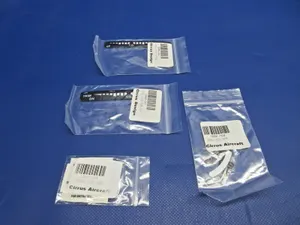
Parts listed for sale by vetted eBay sellers — confirmed on eBay at checkout.