DFC Autopilot Series Installation Manual
Cirrus SR20 · Wiring Diagram
Overview
The DFC Autopilot Series Installation Manual provides comprehensive guidance for the installation of the Avidyne DFC90 and DFC100 autopilot systems specifically designed for the Cirrus 2X aircraft. This manual includes detailed information on system specifications, installation instructions, and troubleshooting procedures. It is intended for use by certified technicians and installers who are responsible for integrating the autopilot systems into the aircraft. The document outlines the necessary components, wiring diagrams, and compliance with regulatory standards, ensuring that the installation meets safety and performance requirements. Additionally, it includes troubleshooting information to assist in diagnosing and resolving common issues that may arise during or after installation.
- The DFC90/100 autopilot systems are designed for the Cirrus 2X aircraft.
- Installation requires adherence to FAA guidelines and STC compliance.
- The DFC90 weighs 3.0 lbs and operates on 18-32 Volts DC.
- Troubleshooting procedures are included for common issues such as AHRS and airdata failures.
- Technical specifications include electrical requirements and cooling needs.
Document
Source
Originally published by www.avidyne.com. Sprinkle hosts a reference copy with an added summary, specifications and searchable full text.
Document details
- Type
- Wiring Diagram
- Year
- 2025
- Pages
- 52
- File size
- 1.2 MB
- Publisher
- www.avidyne.com
Common. One of the most common aircraft types we track.
Most owners only have the POH. Here's the essential set for the Cirrus SR20.
- Pilot's Operating Handbook / AFM
- Checklist
- Maintenance Manual
- Parts Catalog (IPC)
- Systems & Wiring
- Service Bulletins
- Type Certificate (TCDS)
Cirrus SR20 for sale now
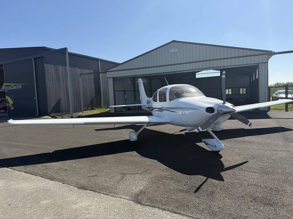
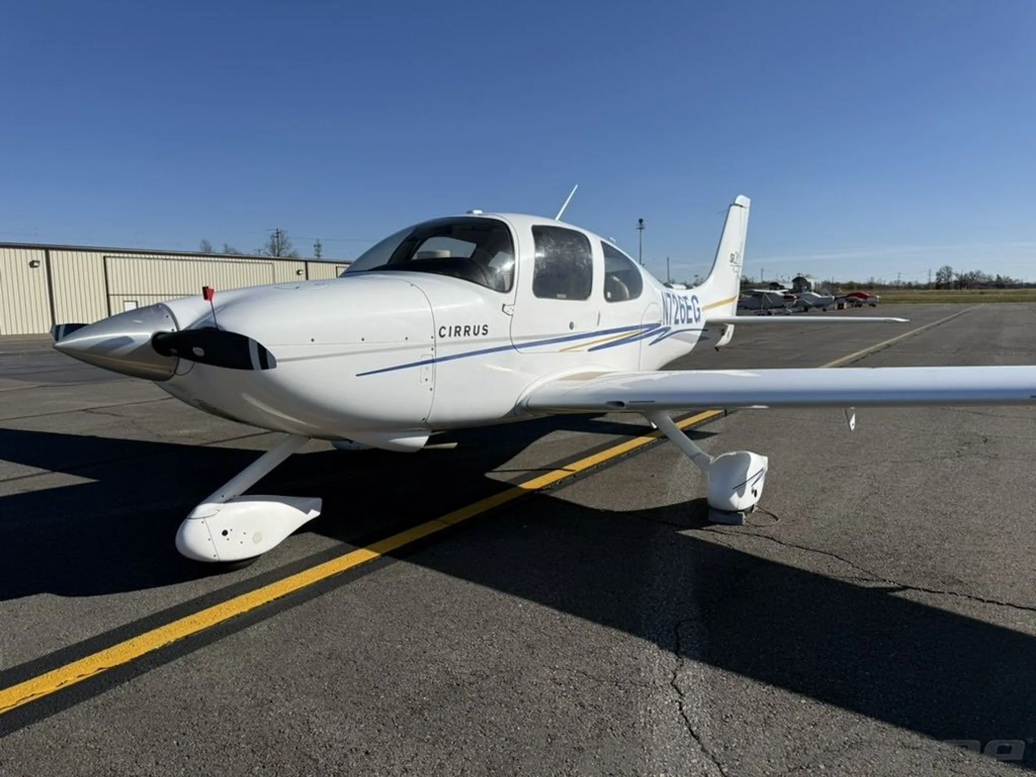

Free — save the SR20 to your watchlist and track it in one place.
More Cirrus SR20manuals & documents
See all 17 →- Cirrus Owners and Pilots Quick Reference Guide for SR Series aircraftV Speeds Reference
- Validation ReportOther Documents
- PILOT’S OPERATING HANDBOOK AND FAA APPROVED AIRPLANE FLIGHT MANUAL for the CIRRUS DESIGN SR20Pilot's Operating Handbook
- Standard Practice Maintenance ManualMaintenance Manual
- Aviation Maintenance Alert - Cirrus SR20 and SR22 AircraftMaintenance Manual
- PILOT’S OPERATING HANDBOOK AND FAA APPROVED AIRPLANE FLIGHT MANUAL for the CIRRUS SR20Training Manual
- CIRRUS SR20 NORMAL CHECKLISTEmergency Procedures
- Dual Fuel Level – Cirrus Aircraft w/ CIES Inc. SendersWiring Diagram
- Pilot’s Operating HandbookPilot's Operating Handbook
- Service BulletinService Bulletins
- AIRWORTHINESS DIRECTIVEAirworthiness Directives
- SERVICE BULLETIN SB 7084Service Bulletins
If you fly the Cirrus SR20, you may also be researching these.


In this document
General Information
This section introduces the DFC90/100 autopilot systems, describing their functionality and integration into the aircraft. It highlights the autopilot's capabilities, such as altitude hold, navigation modes, and more.
Installation Instructions
This section provides step-by-step guidance on installing the DFC autopilot systems, including electrical interface requirements, mounting procedures, and installation limitations. It emphasizes the importance of following FAA guidelines and ensuring compliance with STC requirements.
Technical Specifications
The technical specifications section details the physical and electrical characteristics of the DFC90/100 systems, including weight, voltage requirements, and cooling needs. For instance, the DFC90 weighs 3.0 lbs with connectors and requires 18-32 Volts DC.
Troubleshooting Information
This section outlines common issues that may occur during installation or operation of the autopilot systems, along with recommended solutions. It provides a troubleshooting guide for various annunciations and failures, ensuring that technicians can effectively diagnose problems.
Regulatory Compliance
This section discusses the applicable Technical Standard Orders (TSOs) for the DFC90/100 systems, emphasizing the need for compliance with FAA regulations during installation.
Safety notes
- Ensure compliance with all STC requirements during installation.
- Perform an Electrical Load Analysis to avoid exceeding aircraft limits.
Full document text
DFC Autopilot Series Installation Manual DFC Autopilot Series Installation Manual 600-00251-000 Rev: 10 i Document Revisions Date Revision No. Description 05/25/10 00 Release per ECO-10-163 06/16/10 01 Update per ECO-10-237 07/14/10 02 Update per ECO-10-270 11/05/10 03 Update per ECO-10-384 12/06/10 04 Update per ECO-10-421 11/04/11 05 Update per ECO-11-160 09/25/12 06 Update per ECO-12-195 12/06/12 07 Update per ECO-12-303 05/02/13 08 Update per ECO-13-138 09/02/14 09 Update per ECO-14-218 08/08/25 10 Update per ECO-25-110 This document is applicable to the Avidyne DFC Series of Autopilots. All materials copyrighted, including images that represent this software. Copyright 2010-2025 Avidyne Corporation. All rights reserved. The latest installation manuals are available to authorized dealers on the web at www.avidyne.com. Avidyne is a registered trademark of Avidyne Corporation. DFC Autopilot Series Installation Manual 600-00251-000 Rev: 10 ii THIS PAGE INTENTIONALLY LEFT BLANK. DFC Autopilot Series Installation Manual 600-00251-000 Rev: 10 iii Table of Contents 1. General Information ............................................................................................ 5 1.1 Introduction............................................................................................................. 5 1.2 Product Description ................................................................................................ 5 1.3 Applicability ............................................................................................................ 6 1.4 System Installation ................................................................................................. 8 1.4.1 DFC90 Typical Installation ................................................................................... 8 1.4.2 DFC100 Typical Installation ................................................................................. 9 1.4.3 Compatible Displays ............................................................................................ 9 1.5 Technical Specifications ....................................................................................... 10 1.6 DFC90/100 Regulatory Compliance ..................................................................... 11 1.6.1 Applicable TSOs ................................................................................................ 11 1.6.2 TSO Deviations ................................................................................................. 11 1.7 Software Design Assurance Levels ...................................................................... 12 1.8 Avidyne Supplied Material .................................................................................... 12 1.8.1 Product Ship Kits ............................................................................................... 12 1.8.2 Optional Ship Kits .............................................................................................. 15 2. Installation Instructions ..................................................................................... 17 2.1 Installation Limitations .......................................................................................... 17 2.1.1 DFC90 Limitations ............................................................................................. 18 2.1.2 DFC100 Limitations ........................................................................................... 18 2.2 Installation Considerations .................................................................................... 20 2.3 Cooling ................................................................................................................. 20 2.4 Mounting............................................................................................................... 20 2.5 Electrical Information ............................................................................................ 21 DFC Autopilot Series Installation Manual 600-00251-000 Rev: 10 iv 2.5.1 Electrical Interface ............................................................................................. 21 2.5.2 ByteFlight Databus (DFC100 only) .................................................................... 21 2.5.3 Wire Type .......................................................................................................... 21 2.5.4 DFC90 Pin Assignments .................................................................................... 22 2.5.5 DFC100 Pin Assignments .................................................................................. 24 3. System Setup and Post Installation Checkout .................................................. 26 4. Troubleshooting Information ............................................................................. 27 5. Factory Service Policies and Procedures ......................................................... 32 5.1 Technical Support................................................................................................. 32 5.2 General Service Procedures ................................................................................. 32 6. STC Permission ................................................................................................ 33 Appendix A: Environmental Qualification Forms ......................................................... 34 Appendix B: DFC90/100 Outline Dimensions ............................................................. 36 Appendix C: Autopilot Tray Outline Dimensions ......................................................... 38 Appendix D: Aircraft Inspection ................................................................................... 39 DFC Autopilot Series Installation Manual 600-00251-000 Rev: 10 5 1. General Information 1.1 Introduction This manual contains information about the physical, mechanical, and electrical characteristics for
Show full textShow less
installing the Avidyne DFC90/100 Automatic Pilot System. 1.2 Product Description The DFC90/100 is an Autopilot Control Panel (ACP) and Autopilot Computer integrated into one single unit. The front bezel of the DFC90/100 allows the Flight Crew to select the various flight modes. The DFC90/100 computer receives information from the Aircraft’s Navigation and Flight Instruments to provide two axis (pitch and roll) control of the aircraft. The DFC90/100 Autopilot provides the following flight functions for piloting the aircraft: • Straight & Level • Heading Mode • Navigation (NAV, APPR) • Roll Steering (GPSS) Mode (DFC90 Only) • Altitude Capture and Hold Mode • Vertical Speed Mode • Indicated Airspeed Mode • Glideslope (GS) Mode • VNAV Mode (DFC100 Only) • Control Wheel Steering DFC Autopilot Series Installation Manual 600-00251-000 Rev: 10 6 1.3 Applicability This manual applies to the following part numbers: Component Model Number Aircraft Hardware Part Number Software Part Number Autopilot Control Panel DFC90 Cirrus 2X 700-00170-000 Rev. 01 (or later approved revision) 530-00213-000 Rev. 03 (or later approved revision) Autopilot Control Panel DFC100 Cirrus 2X 700-00170-001 Rev. 02 (or later approved revision) 530-00219-000 Rev 01 (or later approved revision) Autopilot Control Panel DFC90 Piper PA-46R- 350T, PA-46-350P 700-00170-002 Rev. 01 (or later approved revision) 530-00213-001 Rev. 01 (or later approved revision) Autopilot Control Panel DFC100 Piper PA-46R- 350T, PA-46-350P 700-00170-003 Rev. 00 (or later approved revision) 530-00219-001 Rev. 01 (or later approved revision) Autopilot Control Panel DFC90 (28VDC Unit) Cessna 182 Series 700-00170-022 Rev. 00 (or later approved revision) 530-00213-007 Rev. 00 (or later approved revision) Autopilot Control Panel DFC90 (14VDC Unit) Cessna 182 Series 700-00170-024 Rev. 01 (or later approved revision) 530-00213-008 Rev. 00 (or later approved revision) Autopilot Control Panel DFC100 KAI KC-100 700-00170-018 Rev. 01 (or later approved revision) 530-00219-005 Rev. 00 (or later approved revision) Autopilot Control Panel DFC90 (28VDC Unit) Piper PA-32 700-00170-004 Rev. 00 (or later approved revision) 530-00213-002 Rev. 00 (or later approved revision) Autopilot Control Panel DFC90 (14VDC Unit) Piper PA-32 700-00170-005 Rev. 00 (or later approved revision) 530-00213-011 Rev. 00 (or later approved revision) Autopilot Control Panel DFC100 (28VDC Unit) Piper PA-32 700-00170-006 Rev. 00 (or later approved revision) 530-00219-002 Rev. 00 (or later approved revision) Autopilot Control Panel DFC100 (14VDC Unit) Piper PA-32 700-00170-027 Rev. 00 (or later approved revision) 530-00219-012 Rev. 00 (or later approved revision) DFC Autopilot Series Installation Manual 600-00251-000 Rev: 10 7 Component Model Number Aircraft Hardware Part Number Software Part Number Autopilot Control Panel DFC90 (28VDC Unit) Beech Bonanza Series 700-00170-025 Rev. 00 (or later approved revision) 530-00213-009 Rev. 00 (or later approved revision) Autopilot Control Panel DFC90 (14VDC Unit) Beech Bonanza Series 700-00170-026 Rev. 01 (or later approved revision) 530-00213-010 Rev. 00 (or later approved revision) Table 1: Autopilot System Product Part Numbers DFC Autopilot Series Installation Manual 600-00251-000 Rev: 10 8 1.4 System Installation 1.4.1 DFC90 Typical Installation The following figure depicts a typical high-level system block diagram for the DFC90 Autopilot. Figure 1: DFC90 System Interconnect Diagram DFC Autopilot Series Installation Manual 600-00251-000 Rev: 10 9 1.4.2 DFC100 Typical Installation The following figure depicts a typical high-level system block diagram for the DFC100 Autopilot. Figure 2: DFC100 System Interconnect Diagram 1.4.3 Compatible Displays Reference Avidyne Document AVDFC-096, AVDFC-126, AVDFC-167, or AVDFC-181 for compatible displays. DFC Autopilot Series Installation Manual 600-00251-000 Rev: 10 10 1.5 Technical Specifications Specification Description/Requirement Physical Characteristics Weight 3.0 lbs with Tray and Connectors (2.1 lbs Unit) Height See Appendix B Width See Appendix B Depth See Appendix B Connectors (Aircraft Side) M24308/2-285 (50-position female D-Sub) QTY 2 Electrical Requirements Voltage1 18 – 32 Volts DC Current 1.5 Amps nominal, 5.0 Amps Max @ 28VDC nominal Dimming Bus2 28 Volt DC Aircraft Dimming Bus Cooling Requirement Convectively self-cooling, no external cooling required. Interfaces RS232, Analog & Discrete Inputs/Outputs, Byteflight (DFC100 Only) Environmental Requirements DO-160 Appendix A – Environmental Qualification Form TSOs See Section 1.6 Table 2: DFC90/100 Technical Specifications 1 Avidyne Autopilot P/N 700-000170-005/-024/-026/-027 requires a 28VDC input for unit power and a 14VDC input for servo power. 2 Avidyne Autopilot P/N 700-00170-005/-024/-026/-027 uses a 14V Dimming Voltage. DFC Autopilot Series Installation Manual 600-00251-000 Rev: 10 11 1.6 DFC90/100 Regulatory Compliance 1.6.1 Applicable TSOs This section identifies Technical Standard Orders (TSOs) applicable to the Avidyne DFC90/100. The conditions and tests required for TSO approval of this article are minimum performance standards. It is the responsibility of those installing this article either on or within a specific type or class of aircraft to determine that the aircraft installation conditions are within the TSO standards. TSO articles must have separate approvals for installation in aircraft. The article may be installed only if performed under 14 CFR Part 43 or the applicable airworthiness requirements. Table 3: DFC90/100 TSO Authorizations 1.6.2 TSO Deviations Table 4 below lists the TSO deviations and a brief description of the nature of the deviation that have been granted for those applicable TSOs. TSO Deviation TSO-C9c – Autopilot Qualified to RTCA DO-160E TSO-C52b – Flight Director Equipment Qualified to RTCA DO-160E Table 4: DFC90/100 TSO Deviations TSO Number Title TSO-C9c Automatic Pilots TSO-C52b Flight Director Equipment DFC Autopilot Series Installation Manual 600-00251-000 Rev: 10 12 1.7 Software Design Assurance Levels The DFC90/100 Autopilot contains software developed in accordance with RTCA DO-178B Level B design assurance levels. The following table lists the functions of the system and the corresponding design assurance level. Function DO-178B Design Assurance Level Autopilot B Flight Director B Table 5: DO-178B Software Design Assurance Levels 1.8 Avidyne Supplied Material 1.8.1 Product Ship Kits 1) Cirrus 2X DFC90 Ship Kit includes: Component Part Number Adhesive Back Cover Plate, Black 120-00918-000 Adhesive Back Cover Plate, Beige 120-00918-001 DFC90 Autopilot Control Panel 700-00170-000 Airplane Flight Manual Supplement, Cirrus 2X 600-00249-000 DFC90 Pilot Guide 600-00252-000 Installation Support Documentation 609-00012-000 Table 6: Cirrus 2X DFC90 Ship Kit - 850-00170-000 DFC Autopilot Series Installation Manual 600-00251-000 Rev: 10 13 2) Cirrus 2X DFC100 Ship Kit includes: Component Part Number Adhesive Back Cover Plate, Black 120-00918-000 Adhesive Back Cover Plate, Beige 120-00918-001 DFC100 Autopilot Control Panel 700-00170-001 Airplane Flight Manual Supplement, Cirrus 2X 600-00271-000 DFC100 Pilot Guide 600-00270-000 Installation Support Documentation 609-00012-001 Table 7: Cirrus 2X DFC100 Ship Kit - 850-00170-001 3) Piper PA-46R-350T / PA-46-350P DFC90 Ship Kit includes: Component Part Number DFC90 Autopilot Control Panel 700-00170-002 Airplane Flight Manual Supplement, Piper PA-46 600-00285-000 DFC90 Pilot Guide 600-00252-000 Installation Support Documentation 609-00016-000 Table 8: Piper DFC90 Ship Kit - 850-00170-002 DFC Autopilot Series Installation Manual 600-00251-000 Rev: 10 14 4) Piper PA-46R-350T / PA-46-350P DFC100 Ship Kit includes: Component Part Number DFC100 Autopilot Control Panel 700-00170-003 Airplane Flight Manual Supplement, Piper PA-46 600-00288-000 DFC100 Pilot Guide 600-00270-000 Installation Support Documentation 609-00016-001 Table 9: Piper DFC100 Ship Kit - 850-00170-003 5) Cessna 182 Series (28VDC Unit) DFC90 Ship Kit includes: Component Part Number DFC90 Autopilot Control Panel 700-00170-022 Airplane Flight Manual Supplement, Cessna 182 600-00293-000 DFC90 Pilot Guide 600-00252-000 Installation Support Documentation 609-00017-000 Table 10: Cessna 182 Series DFC90 Ship Kit – 850-00170-022 6) Cessna 182 Series (14VDC Unit) DFC90 Ship Kit includes: Component Part Number DFC90 Autopilot Control Panel 700-00170-024 Airplane Flight Manual Supplement, Cessna 182 600-00293-000 DFC90 Pilot Guide 600-00252-000 Installation Support 609-00017-000 DFC Autopilot Series Installation Manual 600-00251-000 Rev: 10 15 Component Part Number Documentation Table 11: Cessna 182 Series DFC90 Ship Kit – 850-00170-024 7) Bonanza Series (28V Unit) DFC90 Ship Kit includes: Component Part Number DFC90 Autopilot Control Panel 700-00170-025 Airplane Flight Manual Supplement, Bonanza Series 600-00297-000 DFC90 Pilot Guide 600-00252-000 Installation Support Documentation 609-00018-000 Table 12: Bonanza Series DFC90 Ship Kit – 850-00170-025 8) Bonanza Series (14V Unit) DFC90 Ship Kit includes: Component Part Number DFC90 Autopilot Control Panel 700-00170-026 Airplane Flight Manual Supplement, Bonanza Series 600-00297-000 DFC90 Pilot Guide 600-00252-000 Installation Support Documentation 609-00018-000 Table 13: Bonanza Series DFC90 Ship Kit – 850-00170-026 1.8.2 Optional Ship Kits 1) DFC90/100 Autopilot Tray: Component Part Number DFC Autopilot Series Installation Manual 600-00251-000 Rev: 10 16 Component Part Number DFC90/100 Autopilot Tray 700-00172-000 Table 14: Autopilot Tray Ship Kit – 850-00213-000 2) ByteFlight Cable: Component Part Number QTY ByteFlight Cable 033-00102-000 40 feet Table 15: Cable Ship Kit – 820-00101-000 Note: Only required for R9 installations with 100-00394-( ) Rev. 00 or 100-00458-000 Rev. 00 Harness installed. DFC Autopilot Series Installation Manual 600-00251-000 Rev: 10 17 2. Installation Instructions This Section describes the installation and interface to the DFC Series Autopilot. Prior to beginning the installation, the installer should assess the aircraft’s flight control system thoroughly. This assessment should include the following: Cable Tensions, Bridle Cable Tensions, Flight Control Rigging, and Servo Clutch Torque Settings. If the installer suspects an issue in any of the above areas, the installer should reference the appropriate section of the approved maintenance data. See Appendix D - Aircraft Inspection for additional inspection details. Any aircraft deficiencies not corrected may result in poor lateral and/or vertical performance of the autopilot. See Section 4 for additional Autopilot troubleshooting information. 2.1 Installation Limitations The following Installation Limitations must be followed during the installation of the Avidyne Automatic Pilot System. Airframe STC Number Master Document List Number Cirrus 2X SA00296BO AVDFC-019 (Includes both the DFC90 and DFC100) Piper PA-46R-350T / PA-46- 350P SA00310BO AVDFC-077 (Includes both the DFC90 and DFC100) Cessna 182 Series1 SA00323BO AVDFC-115 (DFC90 Only) Beech Series1 SA00331BO AVDFC-157 (Includes both the DFC90 and DFC100) Table 16: Applicable STCs 1 Reference the STC for Specific Aircraft Models The Installer MUST use the approved installation drawing(s) (e.g. 900-00XXX-XXX, 700-00170-XXX Installation) as listed in the Master Document List for the specific aircraft type. DFC Autopilot Series Installation Manual 600-00251-000 Rev: 10 18 2.1.1 DFC90 Limitations • Requires existing S-TEC Roll, Pitch and Pitch Trim servos installed per approved STC or TC. • Requires an Avidyne Vantage12 Primary Flight Display, an Entegra Primary Flight Display with Release 8.0 software (or later) with Modification 55 installed or an Aspen PFD. Reference Avidyne Document AVDFC-096 (Cirrus and Piper PA-46 with Entegra or Aspen PFD), AVDFC-126 (Cessna), AVDFC-167 (Beech), AVDFC-181 (Cirrus with Vantage12) for appropriate PFD S/W part number. • Any external AP/FD Annunciation/Switches from the previously installed autopilot system must be removed. • The DFC90 can only be installed on the airframes listed in Table 16 per their respective STC. Reference the STC Master Document List for Installation and Compliance Data. • An Electrical Load Analysis, in accordance with AC 43-13-1B, Chapter 11, must be accomplished to determine that the electrical limits of the specific aircraft are not exceeded. The Electrical Load Analysis, Functional Hazard Assessment and other certification requirements for the aircraft must remain in compliance. • A weight and balance calculation must be performed. DFC90 Autopilot and tray weights are identified in this document. Wiring and bracket weights used for flap sensing must be determined by the installer. Alternately the airplane can be weighed to determine the new weight and balance. The aircraft’s weight and balance information must be updated and made available in the airplane’s AFM/POH. 2.1.2 DFC100 Limitations • Requires existing S-TEC Roll, Pitch and Pitch Trim servos installed per approved STC or TC. • Requires an Avidyne Integrated Flight Display System with Release 9.2.1 software (or later) installed (STC # SA00282BO). Reference Avidyne Document AVDFC-096 for appropriate R9 IFD S/W part number. • Any external AP/FD Annunciation/Switches from the previously installed autopilot system must be removed. • The DFC100 can only be installed on the airframes listed in Table 16 per their respective STC. Reference the STC Master Document List for Installation and Compliance Data. • An Electrical Load Analysis, in accordance with AC 43-13-1B, Chapter 11, must be accomplished to determine that the electrical limits of the specific aircraft are not exceeded. The Electrical Load Analysis, Functional Hazard Assessment and other certification requirements for the aircraft must remain in compliance. DFC Autopilot Series Installation Manual 600-00251-000 Rev: 10 19 • A weight and balance calculation must be performed. DFC100 Autopilot and tray weights are identified in this document. Wiring and bracket weights used for flap sensing must be determined by the installer. Alternately the airplane can be weighed to determine the new weight and balance. The aircraft’s weight and balance information must be updated and made available in the airplane’s AFM/POH. DFC Autopilot Series Installation Manual 600-00251-000 Rev: 10 20 2.2 Installation Considerations The following should be considered prior to starting the installation: • Before you start, plan your installation by carefully reviewing all installation documentation, including mechanical and electrical instructions. • Use the appendices found in this manual for guidance with system component dimensions, cutout dimensions, and wiring. • Follow acceptable avionics installation practices per FAA AC 43.13-1B, AC 43.13-2B, or later FAA approved revisions. • Perform the structural aspects of the installation in accordance with FAA AC 43.13-2B, Chapter 1. • An Electrical Load Analysis, in accordance with AC 43-13-1B, Chapter 11, must be accomplished to determine that the electrical limits of the specific aircraft are not exceeded. The Electrical Load Analysis, Functional Hazard Assessment and other certification requirements for the aircraft must remain in compliance. • The panel assembly must include placard content equivalent to that existing prior to the modification. • Other avionics required for approved flight operations relocated during this installation must remain readily accessible to the pilot. This may require a separate approval. 2.3 Cooling The Avidyne Autopilot Computer requires no external cooling. However, installing an external electric cooling fan will reduce the overall operating temperature of the unit. If the DFC90/100 is installed in a tightly packed avionics stack where the cooling airflow is limited, Installers should consider installing an external cooling fan. The Autopilot should not be installed in a location that is outside the Autopilot’s environmental qualifications. See Appendix A for the Autopilot’s Environmental Qualifications. 2.4 Mounting The Avidyne Autopilot is designed to be installed in an avionics tray. The tray allows the Avidyne Autopilot to be easily installed and removed as necessary. The Autopilot is installed/removed from the tray using a 3/32” Allen wrench. The Allen wrench is inserted into the hole on the front bezel of the Autopilot Computer. The Avidyne Tray should be mounted in a position easily accessible to the Pilot using standard industry practices. DFC Autopilot Series Installation Manual 600-00251-000 Rev: 10 21 2.5 Electrical Information 2.5.1 Electrical Interface Electrical Interfaces should be installed per the installation data for the STC. 2.5.2 ByteFlight Databus (DFC100 only) Avidyne’s Byteflight Databus has a unique set of interconnect requirements. Follow the installation instructions in the STC or contact Avidyne for more information. 2.5.3 Wire Type Wiring aspects of design, including wire type and size selection must conform to FAA AC 43.13-1B, Chapter 11 Section 5, Electrical Wiring Rating. Wire conforming to MIL-W-22759/16 or MIL-C- 27500 satisfies the burn requirements stated in Title 14 CFR ß23.1359. DFC Autopilot Series Installation Manual 600-00251-000 Rev: 10 22 2.5.4 DFC90 Pin Assignments Pin Number P1 – Connector P2 - Connector 1 Roll Motor 2 Not Used 2 Ground Not Used 3 Pitch Motor 2 Roll Solenoid 4 Down Trim Limit Not Used 5 Rate Gyro Tach CWS Input 6 Rate Gyro Reference Ground 7 No Connection 5 VDC Analog Reference 8 No Connection Not Used 9 Not Used Not Used 10 Ground Not Used 11 Not Used Not Used 12 Not Used Not Used 13 Not Used Not Used 14 Not Used Trim Interrupt In 15 Lighting Input Manual Trim - Down Input 16 Ground Manual Trim - Up Input 17 Autopilot Disconnect Switch Trim Motor Down 18 Roll Solenoid Not Used 19 Roll Motor 1 Not Used 20 Pitch Solenoid Not Used 21 Pitch Motor 1 Not Used 22 Up Trim Limit Not Used 23 Ground Manual Trim – Left Input 24 Rate Gyro Signal RS-232 Tx 25 Not Used RS-232 Rx DFC Autopilot Series Installation Manual 600-00251-000 Rev: 10 23 26 Not Used RS-232 Rx 27 Not Used Audio Out HI 28 Not Used Flap Input 29 Not Used Not Used 30 Not Used Flap Position Reference (10VDC) 31 Not Used Flap Input (10VDC max) 32 Not Used Trim Motor Up 33 Not Used Trim Solenoid 34 Power Input No Connection 35 Power Ground No Connection 36 Roll Solenoid Ground Not Used 37 Not Used Not Used 38 Not Used Manual Trim – Right Input 39 Ground Ground 40 Ground Ground 41 Ground Ground 42 Ground Ground 43 Ground Ground 44 Ground Ground 45 Ground Ground 46 Ground Ground 47 Not Used Ground 48 Not Used Ground 49 Not Used Ground 50 Not Used Trim Power Input Table 17: DFC90 Pin Assignments DFC Autopilot Series Installation Manual 600-00251-000 Rev: 10 24 2.5.5 DFC100 Pin Assignments Pin Number P1 – Connector P2 - Connector 1 Roll Motor 2 Not Used 2 Ground Not Used 3 Pitch Motor 2 Roll Solenoid 4 Down Trim Limit Not Used 5 Rate Gyro Tach CWS Input 6 Rate Gyro Reference Ground 7 Byteflight A+ 5 VDC Analog Reference 8 Byteflight A- Not Used 9 Go-Around In Not Used 10 Ground Not Used 11 Not Used Not Used 12 Not Used Not Used 13 Not Used Not Used 14 Not Used Trim Interrupt In 15 Lighting Input Manual Trim - Down Input 16 Ground Manual Trim - Up Input 17 Autopilot Disconnect Switch Trim Motor Down 18 Roll Solenoid Not Used 19 Roll Motor 1 Not Used 20 Pitch Solenoid Not Used 21 Pitch Motor 1 Not Used 22 Up Trim Limit Not Used 23 Ground Manual Trim – Left Input 24 Rate Gyro Signal RS-232 Tx 25 Not Used RS-232 Rx DFC Autopilot Series Installation Manual 600-00251-000 Rev: 10 25 26 Not Used RS-232 Rx 27 Not Used Audio Out HI 28 Not Used Flap Input 29 Not Used Not Used 30 Not Used Flap Position Reference 31 Not Used Flap Input (10VDC max) 32 Not Used Trim Motor Up 33 Not Used Trim Solenoid 34 Power Input Byteflight B+ 35 Power Ground Byteflight B- 36 Roll Solenoid Ground Not Used 37 Not Used Not Used 38 Not Used Manual Trim – Right Input 39 Ground Ground 40 Ground Ground 41 Ground Ground 42 Ground Ground 43 Ground Ground 44 Ground Ground 45 Ground Ground 46 Ground Ground 47 Not Used Ground 48 Not Used Ground 49 Not Used Ground 50 Not Used Trim Power Input Table 18: DFC100 Pin Assignments DFC Autopilot Series Installation Manual 600-00251-000 Rev: 10 26 3. System Setup and Post Installation Checkout Reference Avidyne Document AVDFC-096, AVDFC-126, AVDFC-167, or AVDFC-181 for configuring and testing the Avidyne Autopilot. DFC Autopilot Series Installation Manual 600-00251-000 Rev: 10 27 4. Troubleshooting Information The following items present common installation problems and recommended actions for the Avidyne Autopilot System. Reference the Aircraft Maintenance Manual (AMM) for aircraft related material. Table 19: Troubleshooting Guide Component Trouble Probable Cause Solution Autopilot Annunciations on the Primary Flight Display (DFC90 Only): Primary Flight Display (PFD) AHRS Fail Annunciation Attitude Heading Reference System (AHRS) Failed on the Primary Flight Display (PFD). The ADI and Heading on the PFD has a red X. Repair or Replace the PFD. Airdata Fail Annunciation Airdata Failed on the PFD. The PFD indicates red X’s on Altimeter and Airspeed tape. Repair or Replace the PFD. ADAHRS Fail Annunciation ADAHRS Failed on the PFD. The PFD indicates red X’s on the ADI, Altimeter tape, Airspeed tape, and Heading. Repair or Replace the PFD. Turn Coordinator (N/A for Vantage12) TC Fail Annunciation Autopilot is not receiving the Turn Coordinator Gyro Valid. Check Wiring between the Turn Coordinator and the Autopilot. Check Gyro Valid (>4 VDC) Verify Autopilot is properly seated in its tray. Repair or Replace the Turn Coordinator. Autopilot Self Test Fail Annunciation Autopilot Built In Test Failed. Verify Autopilot is properly seated in its tray. Verify no Autopilot external devices has failed (i.e. trim/servo motors, turn coordinator, autopilot disconnect, trim/servo motor, etc.) Repair or Replace the Autopilot. Autopilot No COMM From Autopilot Annunciation The Autopilot is not communicating with the PFD. Check Wiring between the Autopilot Computer and the PFD. Verify PFD is configured correctly. Verify Autopilot is properly seated in its tray. Verify PFD hardware/software has been updated for the Avidyne Autopilot. Autopilot MSR Fail is displayed on the PFD The autopilot is unable to read or write to the internal Repair or Replace the Autopilot. DFC Autopilot Series Installation Manual 600-00251-000 Rev: 10 28 Component Trouble Probable Cause Solution maintenance and safety recorder. PFD NO PFD COMM Annunciation Autopilot is not receiving data from the PFD. Check Wiring between the Autopilot and the PFD. Repair or Replace the PFD. Verify Autopilot is properly seated in its tray. Repair or Replace the Autopilot. Hardware Modification 55 not installed on PFD Pitch Trim Motor Constant Trim Annunciations Pitch trim motor failure Check Wiring between the Autopilot and the Pitch Trim Motor. Verify Autopilot Trim Motor Voltage is correct to the Trim motor. Repair or Replace Pitch Trim Motor. Repair or Replace the Autopilot. PFD or Turn Coordinator (N/A for Vantage12) AHRS Miscompare Annunciation The AHRS in the PFD differs from the turn rate from the Turn Coordinator. Check PFD and/or Turn Coordinator for any potential problems. Autopilot Autopilot mode indicator lights appear dimly lit or non-functional One string of the LED lights in the autopilot control head are inoperative OR the cockpit lighting rheostat is set to the night position Verify cockpit lighting rheostat not in night position. Repair or Replace the Autopilot. Autopilot No aural alerts heard Autopilot unable to access the internal SD card housing the aural alert files OR connection to the aircraft audio select panel has been lost Check wiring between autopilot and audio select panel (note Pin 27 of autopilot connector P2 is the audio out signal). Repair or Replace the Autopilot. Autopilot Flashes alternatively between blue and white lights The connectors on the back of the DFC90 were reversed and power applied. The DFC90 is unable to get through boot. Repair or Replace the Autopilot. Autopilot Flight Director Command Bars are locked into a fully displaced position (typically commanding full down and left indication). A S-TEC 55 Autopilot Calibration was inadvertently performed with an installed DFC90. Reload the Autopilot Software via Field Loadable Software Service Bulletin and do NOT perform an AP Calibration on the PFD pages. Autopilot Annunciations on the Integrated Flight Display (DFC100 Only): DFC Autopilot Series Installation Manual 600-00251-000 Rev: 10 29 Component Trouble Probable Cause Solution Autopilot Autopilot INOP Annunciation Autopilot Failure Repair or Replace Autopilot Computer R9 IFD AHRS Fail Annunciation R9 IFD AHRS Failed Check R9 IFD annunciations for possible AHRS faults Cycle power and allow R9 IFD system to align Repair or Replace the R9 IFD AHRS Autopilot Self Test Fail Annunciation Autopilot Built In Test Failed. Verify Autopilot is properly seated in its tray. Verify no Autopilot external devices has failed (i.e. trim/servo motors, turn coordinator, autopilot disconnect, trim/servo motor, etc.) Repair or Replace the Autopilot. R9 IFD AHRS Aligning Annunciation R9 IFD AHRS Aligning Wait for the R9 IFD to finish alignment R9 IFD failed to Align. Press “Fast Erect” button on the R9 IFD. R9 IFD Autopilot INOP AHRS Comparator Fail Annunciation (Multiple R9 IFD ADAHRS installations only) One R9 IFD AHRS is not communicating Verify all R9 IFDs on and communicating during aircraft power up. R9 IFD Autopilot INOP AHRS Miscompare Annunciation R9 IFD ADAHRS Check R9 IFD annunciations for possible AHRS faults Cycle power and allow R9 IFD system to align Repair or Replace the R9 IFD ADAHRS R9 IFD/ Autopilot No Communication from the R9 IFD to the DFC Annunciation Wiring, R9 IFD, Autopilot Check Byteflight Wiring Check R9 IFD Databus Status Repair or Replace the R9 IFD Repair or Replace the Autopilot Autopilot Maintenance Safety Recorder Failure Annunciation The autopilot is unable to read or write to the internal maintenance and safety recorder. Repair or Replace the Autopilot Autopilot Audio Unavailable Annunciation The autopilot is unable to read or write to the internal maintenance and safety recorder. Repair or Replace the Autopilot DFC Autopilot Series Installation Manual 600-00251-000 Rev: 10 30 Component Trouble Probable Cause Solution Autopilot Hardware Problems: Autopilot Buttons and/or Knob are unresponsive. Problem with the Autopilot Bezel or wiring. Repair or Replace the Autopilot. Check aircraft wiring Check the Autopilot Circuit Breaker Autopilot Button and/or Bezel backlights not responding to aircraft lighting dimmer. Problem with the Autopilot Bezel or wiring. Check aircraft wiring Repair or Replace the Autopilot. Check Aircraft Lighting Control Autopilot Flight Problems: Autopilot Unexpected Flight Characteristics with Autopilot Engaged in Alt Hold or Vs Climb Moisture in the Static Line – (Note PFD and Standby Instruments will have erratic behavior as well) Check traps and sump for moisture. Check lines for moisture. Perform System Test – Static Plumbing System Unable maintain Altitude (Porpoising) Pitch Servo/Pitch Trim Motor/Flight Control Cables Verify the Cable Tensions on the Aircraft and Bridle Flight Control Cables Verify the Pitch Servo Clutch Settings Check the Start-up Voltages for the Pitch Servo (≤3VDC)π and Pitch Trim Motor (≤5VDC)π. (Reference the AMM for procedure.) Verify the Flight Controls does not have excessive amount of friction Verify Pitch Freeplay (≥2 degrees) Aircraft unable to hold altitude or IAS/VS target accurately at slow speed and forward cg. See Trim Tab Test in AVDFC-096 (Cirrus SR20s without Pitch Servo only) Increase/Decrease in 1 degree increments the adjustable Pitch Trim Tab angle. Repeat the maintenance flight test. Aircraft Wing Rock (S-turns) Roll Trim Motor/Flight Control Cables Verify the Cable Tensions on the Aircraft Flight Controls Check Start-up Voltage for Roll Motor (≤3VDC)π Check Roll excessive Freeplay (>2 degrees) Verify the Flight Controls does not have excessive amount of friction Aircraft Aircraft unable to hold altitude or IAS/VS target accurately at slow speed and forward cg. See Trim Pitch Trim Tab Increase/Decrease in 1 degree increments the adjustable Pitch Trim Tab angle. Repeat the DFC Autopilot Series Installation Manual 600-00251-000 Rev: 10 31 Component Trouble Probable Cause Solution Tab Test in Trim Tab Test in AVDFC-096 (Cirrus SR20s without Pitch Servo only) maintenance flight test. Aircraft Autopilot indicates AP Ready but will not engage. Pitch Trim Power Pitch Trim Circuit Breaker is open. Pitch Trim Relay Removed Check Wiring (14-Volt Only) Pitch Trim Power is below 10.5V π Connect and Measure the startup voltage for the Roll/Pitch Motor using the Power Supply as shown in the image below. This test is using the generic power supply in place of the autopilot to determine what input voltage is required to start the roll/pitch motor to start moving. There are several connector access points within the aircraft to perform this test: For additional troubleshooting information, contact Avidyne Technical Support. See Section 5 for contact information. DFC Autopilot Series Installation Manual 600-00251-000 Rev: 10 32 5. Factory Service Policies and Procedures 5.1 Technical Support Avidyne’s website contains information that may assist the operator and installer with questions or problems with their Avidyne Autopilot System. www.Avidyne.com Technical support questions may be submitted via the following: • Email: techsupport@avidyne.com • Fax: 781-402-7599 • Voice: 888-723-7592 An Avidyne Technical Support Representative will respond as soon as possible. Avidyne business hours are: • Monday through Friday: 8:00 AM to 5:00 PM Eastern Time Please include the part number, revision number and serial number of the unit in all correspondences. For problem reporting, please provide as many details associated with the problem as possible. For After Hours Technical Support, via the following: • AOG Support: 877-900-4AOG (4264) 5.2 General Service Procedures Repair of the DFC90/100 are performed at authorized Part 145 service centers and the Avidyne factory. Prior to returning a unit for service, contact Avidyne at 1-888-723-7592 to obtain a Return Merchandise Authorization (RMA) number. Securely pack the unit in the Avidyne shipping carton, write the RMA number on the outside of the carton, and return it to the address provided by the Avidyne Customer Service Representative. Include your name, complete shipping address, daytime telephone number, a complete description of the problem, the desired return date, and shipping method. If the shipping carton or other suitable foam packing is not available, contact Avidyne to arrange for packaging materials. Avidyne is not responsible for damage due to poorly packaged returns. DFC Autopilot Series Installation Manual 600-00251-000 Rev: 10 33 6. STC Permission Avidyne Corporation hereby grants to all National Aviation Authority (FAA, CAA, JAA) approved installers the use of data from STC SA00296BO, SA00310BO, SA00323BO, or SA00331BO to install the Avidyne DFC90/100 Autopilot Computer. This also includes any international validations of the listed STCs (e.g. EASA, ANAC, etc). Copies of the STC data are available on the Avidyne website Technical Publications page or upon request. The latest data revisions are listed in Avidyne 700-00170-XXX STC Master Document List (Ref. Table 16). Installers must abide by the conditions and limitations stated in both the STC and in the Installation Manual in order to maintain compliance. The use of this data by itself does not constitute installation approval. DFC Autopilot Series Installation Manual 600-00251-000 Rev: 10 34 Appendix A: Environmental Qualification Forms AUTOPILOT AUTO CONTROL PANEL PART NO: 700-00170-( ) MANUFACTURER: AVIDYNE CORPORATION ADDRESS: 55 OLD BEDFORD ROAD, LINCOLN, MA 01773 Table 20: DO-160E ENVIRONMENTAL QUALIFICATION Environmental Tests RTCA/DO-160E Section Conducted Test Category Temperature and Altitude Low Temp 4.5.1 & 4.5.2 Equipment to be qualified to Category D1 High Temp 4.5.3 & 4.5.4 Equipment to be qualified to Category D1 In-Flight Loss of Cooling 4.5.5 Equipment identified as Category X, no test required Altitude 4.6.1 Equipment to be qualified to Category D1 Decompression 4.6.2 Equipment to be qualified to Category A1 Overpressure 4.6.3 Equipment to be qualified to Category A1 Temperature Variation 5 Equipment to be qualified to Category B Humidity 6 Equipment to be qualified to Category A Operational Shocks & Crash Safety 7 Equipment to be qualified to Category B Vibration 8 Equipment to be qualified to Category S, Curves B & M Explosion Proofness 9 Equipment identified as Category X, no test required Waterproofness 10 Equipment identified as Category X, no test required Fluids Susceptibility 11 Equipment identified as Category X, no test required Sand and Dust 12 Equipment identified as Category X, no test required Fungus Resistance 13 Equipment identified as Category X, no test required Salt Spray 14 Equipment identified as Category X, no test required Magnetic Effects 15 Equipment to be qualified to Category Z DFC Autopilot Series Installation Manual 600-00251-000 Rev: 10 35 Environmental Tests RTCA/DO-160E Section Conducted Test Category Power Input 16 Equipment to be qualified to Category B Voltage Spike 17 Equipment to be qualified to Category A Audio Frequency Conducted Susceptibility 18 Equipment to be qualified to Category B Induced Signal Susceptibility 19 Equipment to be qualified to Category ZC Radio Frequency Susceptibility 20 Equipment to be qualified to Category R (Conducted), Category R (Radiated) Emission of Radio Frequency Energy 21 Equipment to be qualified to Category M Lightning Induced Transient Susceptibility 22 Equipment to be qualified to Category (B3/B4)K44 Lightning Direct Effects 23 Equipment identified as Category X, no test required Icing 24 Equipment identified as Category X, no test required Electrostatic Discharge 25 Equipment to be qualified to Category A Fire/Flammability 26 Equipment identified as Category X, no test required DFC Autopilot Series Installation Manual 600-00251-000 Rev: 10 36 Appendix B: DFC90/100 Outline Dimensions Figure B-1: Front View Figure B-2: Side View DFC Autopilot Series Installation Manual 600-00251-000 Rev: 10 37 Figure B-3: Top View Figure B-4: Rear View (P1 is the left connector) DFC Autopilot Series Installation Manual 600-00251-000 Rev: 10 38 Appendix C: Autopilot Tray Outline Dimensions Figure C-1: Front View Figure C-2: Top View Figure C-3: Side View DFC Autopilot Series Installation Manual 600-00251-000 Rev: 10 39 Appendix D: Aircraft Inspection This Aircraft Inspection is only needed to investigate problems found during the assessment identified in Section 2. Perform steps in this section appropriate to the problem identified/suspected in Section 2. The installer should reference the appropriate section of the approved maintenance data, if needed. See Section 4 for additional Autopilot troubleshooting information. Note: Improper aircraft rigging, such as misaligned aileron or elevator trim tabs, can cause continuous trim activity or degraded autopilot performance after DFC90 installation. This may present as excessive servo movement, poor altitude or heading hold, or instability in pitch or roll. If these symptoms are observed, consult the Cirrus Aircraft Maintenance Manual section 57-50 for rigging instructions. 1. Aircraft Flight Control Evaluation These tests are designed to test the flight control system to ensure optimal performance of the Autopilot. Any inspection/repair/maintenance must be conducted per the Aircraft Manufacturer’s Maintenance Manual or approved Service Bulletin. a. Aileron Flight Control Evaluation The following tests/inspections will evaluate the aircraft’s aileron flight control system. i. Aileron Cable Tension Check Verify the aileron cable tension per aircraft maintenance manual data applicable to the test aircraft. Record the measured value below: Aileron Cable Tension: ________________ ii. Aileron Control Surface Travel Check Verify the aileron control surface travel per aircraft maintenance manual data applicable to the test aircraft. Record the measured values below: Left Aileron Up Travel: __________ Right Aileron Up Travel: _________ Left Aileron Down Travel: _________ Right Aileron Down Travel: _________ iii. Aileron Trim Motor Test 1. Aileron Servo Travel Check DFC Autopilot Series Installation Manual 600-00251-000 Rev: 10 40 Verify the aileron trim control surface travel per aircraft maintenance manual data applicable to the test aircraft. Record the measured values below: Left Aileron Servo Up Travel: _______ Right Aileron Servo Up Travel: _______ Left Aileron Servo Down Travel: _______ Right Aileron Servo Down Travel: _______ 2. Aileron Servo Motor Voltage Test Note: This test is conducted using the S-TEC Autopilot. If the DFC90 Autopilot has already been installed, see the end of Table 19, Troubleshooting Table in Section 4 for an alternative test method. This test is to evaluate the minimum voltage required to move the Aileron Trim Motor. 1. Gain access to the Aileron Roll Servo 2. Connect a Volt Meter between the motor drive lines (for Cirrus SR2X : Pins 1 and 2 at the P304 Disconnect. Note: If P304 is not accessible using an alternate location is acceptable. If using an S-TEC breakout box, measure the voltage between Pins 1 and 19 on connector P551.) 3. Turn on Autopilot power 4. Sync Heading Bug to the current heading 5. Engage the Autopilot in Heading Mode 6. Vary Heading Bug on the PFD in 1 degree increments and record the DC Voltage where the Roll Motor starts to move. Voltage: ___________ Figure 3: Roll Trim Motor Electrical Disconnect DFC Autopilot Series Installation Manual 600-00251-000 Rev: 10 41 Note: Installers should inspect the flight control system for excessive friction and/or roll motor problem if greater than 3 VDC is measured. iv. Aileron Flight Control Freeplay Measurement This test will measure the amount of Aileron freeplay in the Flight Control System from the Roll Trim Cartridge. Aileron Freeplay – Up Measurement 1. Center the Roll Trim for 0 ± .5 degrees of Roll 2. Attach Inclinometer to the Right Aileron to measure deflection angle (Ref. Aircraft Maintenance Manual ) 3. Set Inclinometer to 0 degrees 4. Using both hands, move the aileron up until resistance is felt 5. Slowly remove hands allowing the aileron to center by itself 6. Record Deflection Angle (See Figure 4). Note: Deflection should be ≤ 2 degrees. Inspect Flight Control System if greater than 2 degrees. Aircraft with greater than 2 degrees of Freeplay should inspect the flight control system for potential problems. Up Aileron Freeplay: ___________ Figure 4: Up Aileron Deflection Aileron Freeplay – Down Measurement 1. Center the Roll - ailerons 0 ± .5 degrees of center 2. Attach Inclinometer to the Right Aileron to measure deflection angle (Ref. Aircraft Maintenance Manual ) 3. Set Inclinometer to 0 degrees 4. Using both hands, move the aileron down until resistance is felt 5. Slowly remove hands allowing the aileron to center by itself DFC Autopilot Series Installation Manual 600-00251-000 Rev: 10 42 6. Record Deflection Angle (See Figure 5). Note: Deflection should be ≤ 2 degrees. Inspect Flight Control System if greater than 2 degrees. Aircraft with Freeplay greater than 2 degrees should inspect the flight controls for potential problems. 7. Down Aileron Freeplay: ___________ Figure 5: Down Aileron Deflection b. Elevator Flight Control Evaluation The following tests/inspections will evaluate the Aircraft’s elevator flight control system. i. Elevator Control Surface Travel Check Verify the Elevator control surface travel per the aircraft maintenance manual. Record the measured values below: Up Travel: __________ Down Travel: _________ ii. Pitch Cable Tension Check Verify the Pitch Cable Tension per the aircraft maintenance manual. Record the measured value below: Pitch Cable Tension: _____________ c. Autopilot Pitch Servo Check This Section will evaluate the Aircraft’s Autopilot Pitch Servo. Please note, some SRV/SR20s do not have a Pitch Servo installed, therefore, Section ii below will not apply i. Bridle Cable Tension Check DFC Autopilot Series Installation Manual 600-00251-000 Rev: 10 43 Verify the Pitch Bridle Cable Tension per the aircraft maintenance manual. The measured value below: Pitch Bridle Cable Tension: __________ ii. Pitch Servo Voltage Check This test will evaluate the minimum starting voltage for the Autopilot Pitch Servo. Note: This test is conducted using the S-TEC Autopilot 1. Gain Access to the Pitch Servo Motor 2. Connect 28VDC from a Power Supply to the servo solenoid 3. Connect a second Power Supply between Pins 3 and 4 at the P561 Disconnect. 4. Slowly increase the voltage on the second power from 0 VDC to 5 VDC. 5. Note the Voltage the servo starts moving. 6. Record Voltage below Voltage: ___________ Note: Installers should inspect the flight control system for excessive friction and/or pitch trim motor problem for Voltages greater than 3 VDC. iii. Cirrus SR20/SRV Pitch Trim Motor Test Pitch Trim Travel Check Verify the Pitch Trim control surface travel per the aircraft maintenance manual. Record the measured values below: Pitch Trim Up Travel: __________ Pitch Trim Down Travel: _________ iv. Pitch Trim Motor Voltage Test This test is to evaluate the starting voltage for the Pitch Servo. Use Section 1 below for SR22 and PA46 or Section 2 for a Cirrus SR20/SRV. 1. Pitch Trim Test Note: This test is conducted using the STEC Autopilot 1. Gain access to the Pitch Trim Motor DFC Autopilot Series Installation Manual 600-00251-000 Rev: 10 44 2. Connect a Volt Meter between the servo drive lines (for Cirrus: Pins 1 and 2 at the P634 Disconnect Note: If P634 is not accessible using an alternate location is acceptable.) 3. Turn on autopilot and avionics power 4. Sync Heading Bug to the current heading 5. Set Vs Bug +300 Ft/min Climb 6. Engage the Autopilot in Heading and Vs 7. Push against the control yoke (Pitch Down) – apply pressure against the autopilot but do not override (move) the surface. 8. Press HOLD on the Voltmeter when pitch trim starts to move 9. Record Voltage below Voltage: ___________ Note: Installers should inspect the flight control system for excessive friction and/or pitch trim motor problem for Voltages greater than 5 VDC. 2. Cirrus SR20 Pitch Trim Test Note: This test is conducted using the STEC Autopilot 1. Gain access to the Pitch Trim Motor 2. Aircraft without a Pitch Servo use Step a below. Aircraft with a Pitch Servo use Step b below: a. Connect a Volt Meter between Pins 1 and 2 at the P634 Disconnect Note: If P634 is not accessible using an alternate location is acceptable. If using an S-TEC breakout box, measure the voltage between Pins 3 and 21 on connector P551. b. Connect a Volt Meter between Pins 1 and 2 at the P634 Disconnect Note: If P634 is not accessible using an alternate location is acceptable. If using an S-TEC breakout box, Figure 6: Cirrus SR22 Pitch Trim Motor Electrical Disconnect DFC Autopilot Series Installation Manual 600-00251-000 Rev: 10 45 measure the voltage between Pins 17 and 32 on connector P552. 3. Turn on BATT 1 and Avionics Switches 4. Sync Heading Bug to the current heading 5. Set Vs Bug +100 Ft/min Climb 6. Engage the Autopilot in Heading and Vs 7. Push against the control yoke (Pitch Down) Note: Aircraft without a Autopilot Pitch Servo can eliminate this step. 8. Press HOLD on the Voltmeter when pitch trim starts to move 9. Record Voltage below Voltage: ___________ Note: Installers should inspect the flight control system for excessive friction and/or pitch trim motor problem for Voltages greater than 5 VDC. v. Elevator Flight Control Freeplay Measurement This Section will test the amount of freeplay in the Aircraft’s Elevator System. Note: For Cirrus aircraft with excessive elevator freeplay should inspect the aircraft’s flight control system for any potential problems. Also, see Cirrus Service Bulletin SB 2X-27-12 R1 (or later approved additions). vi. Elevator Freeplay – Up Measurement 1. Center the Pitch Trim for 0 ± .5 degrees of Pitch 2. Attach Inclinometer to the elevator to measure deflection angle (Ref. Aircraft Maintenance Manual ) 3. Set Inclinometer to 0 degrees 4. Using both hands, move the elevator up until resistance is felt Figure 7: Cirrus SR20 Pitch Trim Motor Electrical Disconnect DFC Autopilot Series Installation Manual 600-00251-000 Rev: 10 46 5. Slowly remove hands allowing the elevator to center by itself (See Figure 8). 6. Record Deflection Angle below. Note: Deflection should be ≤ 2 degrees. Aircraft with Freeplay greater than 2 degrees should inspect the flight controls for potential problems. Figure 8: Elevator Up Deflection Elevator Freeplay – Up: __________ Elevator Freeplay – Down Measurement 1. Center the Pitch Trim for 0 ± .5 degrees of Pitch 2. Attach Inclinometer to the elevator to measure deflection angle (Ref. Aircraft Maintenance Manual ) 3. Set Inclinometer to 0 degrees 4. Using both hands, move the elevator up until resistance is felt 5. Slowly remove hands allowing the elevator to center by itself (See Figure 9). 6. Record Deflection Angle below. Note: Deflection should be ≤ 2 degrees. Aircraft with Freeplay greater than 2 degrees should inspect the flight controls for potential problems. Figure 9: Elevator Freeplay - Down Elevator Freeplay – Down: __________ DFC Autopilot Series Installation Manual 600-00251-000 Rev: 10 47 AVIDYNE EXCLUSIVE LIMITED WARRANTY and LIMITATIONS ON LIABILITY Avidyne warrants the Product manufactured by it against defects in material and workmanship for a period of twenty-four (24) months from delivery. If Avidyne's Product fails to conform to this warranty, Avidyne, in its sole discretion, will either repair or replace the Product or provide a refund of the purchase price paid for the Product. This warranty is made upon the express conditions that: (a) Avidyne is given prompt written notice of any claimed non-conformity in the Product, with a reasonable explanation thereof; (b) The Product is returned to Avidyne or to an Avidyne authorized service facility; (c) The Product has not been altered in any manner other than as previously authorized by Avidyne in writing; and (d) Repairs to the Product have not been made by anyone other than Avidyne or an Avidyne authorized service facility. This warranty does not apply to any Product which is not installed, maintained and operated in accordance with Avidyne's written instructions or which is otherwise misused, including, without limitation, to any Product which is damaged due to improper installation, maintenance or operation, tampering, alteration of serial numbers or other manufacturers data, lightning or other electrical source, or otherwise. If warranty protection is applicable to the Product, Avidyne will use reasonable efforts to repair or replace Product within ten (10) business days of its receipt of the Product. Any Product that has been repaired by Avidyne or replaced by Avidyne under this warranty will be subject to remainder of the original warranty term applicable to the repaired or replaced Product or will be warranted under the warranty terms above for ninety days from the date of repair or replacement, whichever period is longer. THIS EXCLUSIVE LIMITED WARRANTY APPLIES IN LIEU OF AND EXPRESSLY SUPERCEDES AND EXCLUDES ALL OTHER REPRESENTATIONS, AFFIRMATIONS AND/ OR WARRANTIES, WHETHER EXPRESS OR IMPLIED, ORAL OR WRITTEN, INCLUDING, WITHOUT LIMITATION, ANY WARRANTY OF MERCHANTABILITY, OF FITNESS FOR A PARTICULAR PURPOSE, OF TITLE AND/OR OF NON-INFRINGEMENT. PURCHASER EXPRESSLY AND KNOWINGLY AGREES THAT NO OTHER REPRESENTATIONS, AFFIRMATIONS OR WARRANTIES, WHETHER EXPRESS OR IMPLIED, ORAL OR WRITTEN, FORM PART OF ANY PURCHASE AND SALE TRANSACTION RELATED TO THE PRODUCT. AVIDYNE'S (AND ITS AFFILIATES') AND ANY PRODUCT COMPONENT SUPPLIER'S SOLE RESPONSIBILITY AND LIABILITY RELATED TO THE PRODUCT OR ARISING OUT OF OR RELATED TO ITS PURCHASE, SALE, PERFORMANCE, RELIABILITY OR USE ARE LIMITED TO ITS REPAIR OR REPLACEMENT, OR TO A REFUND OF THE PURCHASE PRICE, IN AVIDYNE'S SOLE DISCRETION. IN NO EVENT WILL AVIDYNE (OR ITS AFFILIATES) OR ANY SUPPLIERS OF PRODUCT COMPONENTS BE RESPONSIBLE OR LIABLE FOR ANY OTHER DAMAGE OF ANY NATURE WHATSOEVER, INCLUDING DIRECT, INDIRECT, INCIDENTAL, CONSEQUENTIAL, SPECIAL, LOSS OF USE, LOSS OF REVENUE OR PROFIT, PROPERTY DAMAGE, PERSONAL INJURY, WRONGFUL DEATH, OR OTHER DAMAGE (WHETHER OR NOT AVIDYNE (OR ITS AFFILIATES) WERE NOTIFIED OF THE POSSIBILITY THAT ANY DAMAGE MIGHT BE INCURRED), ARISING OUT OF OR RELATED TO THE PRODUCT, ITS PURCHASE OR SALE, ITS PERFORMANCE OR RELIABILITY, OR THE USE OR INABILITY TO USE THE PRODUCT, FOR ANY REASON, INCLUDING DUE TO ANY PRODUCT DEFECT OR DEFECTS OR ANY ACTION OR INACTION OF ANY NATURE (INCLUDING CLAIMED OR ACTUAL NEGLIGENCE OR GROSS NEGLIGENCE) BY AVIDYNE OR ANY SUPPLIERS OF PRODUCT COMPONENTS. NEITHER THIS EXCLUSIVE LIMITED WARRANTY NOR AVIDYNE'S OR ANY PRODUCT COMPONENT SUPPLIER'S RESPONSIBILITY OR LIABILITY WILL IN ANY WAY BE ENLARGED OR OTHERWISE ALTERED DUE TO AVIDYNE'S PROVISION OF TECHNICAL SUPPORT OR TRAINING RELATED TO THE PRODUCT. DFC Autopilot Series Installation Manual 600-00251-000 Rev: 10 48 WITHOUT LIMITING THE FOREGOING, NEITHER AVIDYNE (NOR ITS AFFILIATES) MAKE ANY REPRESENTATIONS, AFFIRMATIONS OR WARRANTIES REGARDING OR RELATED TO PRODUCTS NOT MANUFACTURED BY AVIDYNE OR REGARDING OR RELATED TO THE PERFORMANCE OR RELIABILITY OF ANY SUCH PRODUCT, EITHER ALONE OR WHEN USED WITH ANY PRODUCT MANUFACTURED BY AVIDYNE, OR THE SUITABILITY OF ANY SUCH PRODUCT FOR USE WITH ANY PRODUCT MANUFACTURED BY AVIDYNE. AVIDYNE (AND ITS AFFILIATES) EXPRESSLY DISCLAIM ANY AND ALL REPRESENTATIONS, AFFIRMATIONS AND/OR WARRANTIES REGARDING OR RELATED TO ANY SUCH PRODUCTS. IN NO EVENT WILL AVIDYNE (OR ITS AFFILIATES) BE RESPONSIBLE OR LIABLE FOR ANY DAMAGE OF ANY NATURE WHATSOEVER, INCLUDING DIRECT, INDIRECT, INCIDENTAL, CONSEQUENTIAL, SPECIAL, LOSS OF USE, LOSS OF REVENUE OR PROFIT, PROPERTY DAMAGE, PERSONAL INJURY, WRONGFUL DEATH, OR OTHER DAMAGE (WHETHER OR NOT AVIDYNE (OR ITS AFFILIATES) WERE NOTIFIED OF THE POSSIBILITY THAT ANY DAMAGE MIGHT BE INCURRED), ARISING OUT OF OR RELATED TO PRODUCTS NOT MANUFACTURED BY AVIDYNE, THE PURCHASE OR SALE OF SUCH PRODUCTS, THEIR PERFORMANCE OR RELIABILITY, EITHER ALONE OR WHEN USED WITH ANY PRODUCT MANUFACTURED BY AVIDYNE, OR THE SUITABILITY OF ANY SUCH PRODUCT FOR USE WITH ANY PRODUCT MANUFACTURED BY AVIDYNE. THIS EXCLUSIVE LIMITED WARRANTY ALSO APPLIES IN LIEU OF AND EXPRESSLY SUPERCEDES AND EXCLUDES ALL OTHER RIGHTS ANY PURCHASER HAS OR MAY HAVE RELATED TO THE PRODUCT AND/OR ARISING OUT OF OR RELATED TO ITS PURCHASE, SALE, PERFORMANCE, RELIABILITY OR USE, EITHER ALONE OR WITH ANY OTHER PRODUCT OR PRODUCTS, WHETHER IN CONTRACT, IN TORT (INCLUDING RIGHTS SOUNDING IN NEGLIGENCE, STRICT LIABILITY AND MISREPRESENTATION), UNDER STATUTE, AT LAW, IN EQUITY, OR OTHERWISE, AND PURCHASER EXPRESSLY AND KNOWINGLY WAIVES ALL SUCH RIGHTS TO THE FULLEST EXTENT PERMITTED BY LAW. PURCHASER ALSO EXPRESSLY AND KNOWINGLY AGREES THAT THE PRODUCT IS NOT A CONSUMER GOOD. THE FOREGOING FOUR PARAGRAPHS DEFINE AND LIMIT AVIDYNE'S SOLE RESPONSIBILITY AND LIABILITY AND PURCHASER'S SOLE AND EXCLUSIVE REMEDIES RELATED TO THE PRODUCT. Some jurisdictions may not allow the exclusion or limitation of warranties or liabilities, in which case the above limitations or exclusions, or some of them, may not apply in those jurisdictions. DFC Autopilot Series Installation Manual 600-00251-000 Rev: 10 49 Software License Avidyne Corporation (“Avidyne”) is willing to license this software, pilot's guide, and related materials (the “Software”) only on the condition that you agree to all the terms of this agreement. Please read these terms carefully. Trademarks Avidyne and the Avidyne logo are trademarks of Avidyne Corporation. Other brands or products are the trademarks or registered trademarks of their respective holders and should be treated as such. License and Certain Restrictions You may use the Software on the DFC90/100 on which it was delivered. You may not copy the Software for any purpose. You may not transfer the Software or any rights under this Agreement to another party without this Agreement. The other party must agree to accept the terms of this Agreement. The Software contains trade secrets. You may not decompile, reverse engineer, disassemble, or otherwise reduce the Software to human-readable form. You may not modify, adapt, translate, rent, sublicense, assign, lease, loan, resell for proof, distribute, or network the Software, disk or related materials or create derivative works based upon the software or any part thereof. Title, ownership rights, and intellectual property rights in and to the Software belongs to Avidyne and its licensors. The Software is protected by the copyright laws of the United States and by international copyright treaties. Title, ownership rights and intellectual property rights in and to the content accessed through the Software is the property of Avidyne, and where applicable, to the licensor content owners and may be protected by applicable copyright or other law. This Agreement gives you no rights to such content. Government Licensee If you are acquiring the Software on behalf of any unit or agency of the United States Government, this provision applies. The Government acknowledges Avidyne's representation that the Software and its documentation were developed at private expense and no part of them is in the public domain. The Government acknowledges Avidyne's representation that the Software is “Restricted Computer Software” as that term is defined in Clause 52.227-19 of the Federal Acquisition Regulations (FAR) and is “Commercial Computer Software” as that term is defined in Subpart 227.401 of the Department of Defense Federal Acquisition Regulation Supplement (DFARS). The Government agrees that: If the Software is supplied to the Department of Defense (DoD), the Software is classified as “Commercial Computer Software” and the Government is acquiring only “restricted rights” in the Software and its documentation as that term is defined in Clause 52.227-7013(c)(1) of the DFARS, and If the Software is supplied to any unit or agency of the United States Government other than DoD, the Government's rights in the Software and its documentation will be as defined in Clause 52.227-19(c)(2) of the FAR. Restricted Rights Legend Use, duplication, or disclosure by the Government is subject to restrictions as set forth in subparagraph (c)(1)(ii) of the Rights in Technical Data and Computer Software clause at DFARS 52.227-7013, and when applicable subparagraphs (a) through (d) of the Commercial Computer-Restricted rights clause at FAR 52.227-19, and in similar clauses in the NASA FAR Supplement. - Avidyne Corporation, 55 Old Bedford Road, Lincoln, MA 01773. Export Law Assurances You acknowledge and agree that the Software is subject to restrictions and controls imposed by the United States Export Administration Act and Arms Export Control Act (the “Acts”) and the regulations thereunder. You agree and certify that neither the Software nor any direct product thereof is being or will be acquired, shipped, transferred or exported, directly or indirectly, into any country prohibited by the Acts and the regulations thereunder or will be used for any purpose prohibited by the same. Miscellaneous DFC Autopilot Series Installation Manual 600-00251-000 Rev: 10 50 This Agreement will be governed by the internal laws of the State of Massachusetts. If any provision of this Agreement is held to be unenforceable, that provision will be removed and the remaining provisions will remain in full force. This Agreement is the complete and exclusive statement of the agreement between us which supersedes any other communications between us in relation to the subject matter of this Agreement. This Software contains dated information. Use of the Software is based on your understanding that this Software may not include all the information or the most current information relevant to your particular situation. If you have any questions concerning this Agreement, you may contact Avidyne by writing to Avidyne Corporation, 55 Old Bedford Road, Lincoln, MA 01773. You acknowledge that, in providing you with the Software, Avidyne and its licensors rely upon you to read this Agreement, understand it, and agree to be bound by its terms and not those contained in your purchase order. If you do not agree to the terms of this license, Avidyne is unwilling to license the product to you. In such event, you may not use or copy the product, and you should promptly contact Avidyne for instructions on return of the unused product(s) for a refund. Copyright © 2010-2014 Avidyne Corporation. All rights reserved. Reproduction of this publication or any portion thereof by any means without the express written consent of Avidyne Corporation is prohibited. For further information contact Avidyne Corporation, 55 Old Bedford Road, Lincoln, MA 01773, 781-402-7400. Information in this document is subject to change without notice. Avidyne reserves the right to change or improve their products and to make changes in the content of this material without obligation to notify any person or organization of such changes or improvements. DFC Autopilot Series Installation Manual 600-00251-000 Rev: 10 51 AVIDYNE CORPORATION 55 Old Bedford Road Lincoln, MA 01773 Telephone: 781-402-7400 www.avidyne.com
What's in the Cirrus SR20 TCDS
A Type Certificate Data Sheet (TCDS) is the FAA's record of what an aircraft type was approved as. It is the source of truth for weights, seating, fuel and the rules the design was certified against. Expand any line to see what it means.
844 Cirrus SR20 parts for sale
See all →
Parts listed for sale by vetted eBay sellers — confirmed on eBay at checkout.