Pilot’s Operating Handbook
Cirrus SR22 G2 · Pilot's Operating Handbook
Overview
This Pilot's Operating Handbook (POH) provides essential pre-flight and in-flight operating procedures for the S-TEC System Fifty Five X Autopilot installed in the Cirrus SR20 and SR22 aircraft. It is designed to assist pilots in managing cockpit workload effectively. The handbook includes detailed instructions on the autopilot's modes of operation, pre-flight tests, and in-flight procedures, ensuring that pilots can utilize the autopilot safely and efficiently. It emphasizes the importance of understanding the autopilot's functions in Visual Meteorological Conditions (VMC) before using it under Instrument Flight Rules (IFR).
- The POH is essential for understanding the S-TEC System Fifty Five X Autopilot in Cirrus SR20 and SR22 aircraft.
- Pilots must perform a Power-Up Test and Pre-Flight Test to ensure autopilot functionality before flight.
- The autopilot has various modes, including HDG, NAV, and APR, each with specific activation procedures.
- Understanding the operating parameters is crucial for safe autopilot use during flight.
- The handbook should always be available to the pilot during operations.
Document
Source
Originally published by genesys-aerosystems.com. Sprinkle hosts a reference copy with an added summary, specifications and searchable full text.
Document details
- Type
- Pilot's Operating Handbook
- Year
- 2007
- Pages
- 72
- File size
- 2.2 MB
- Publisher
- genesys-aerosystems.com
Common. Rarer than 7% of the aircraft models we track.
Most owners only have the POH. Here's the essential set for the Cirrus SR22 G2.
- Pilot's Operating Handbook / AFM
- Checklist
- Maintenance Manual
- Parts Catalog (IPC)
- Systems & Wiring
- Service Bulletins
- Type Certificate (TCDS)
Cirrus SR22 G2 for sale now

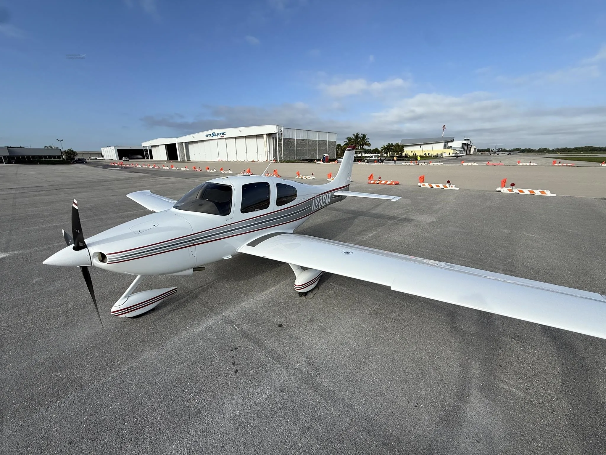
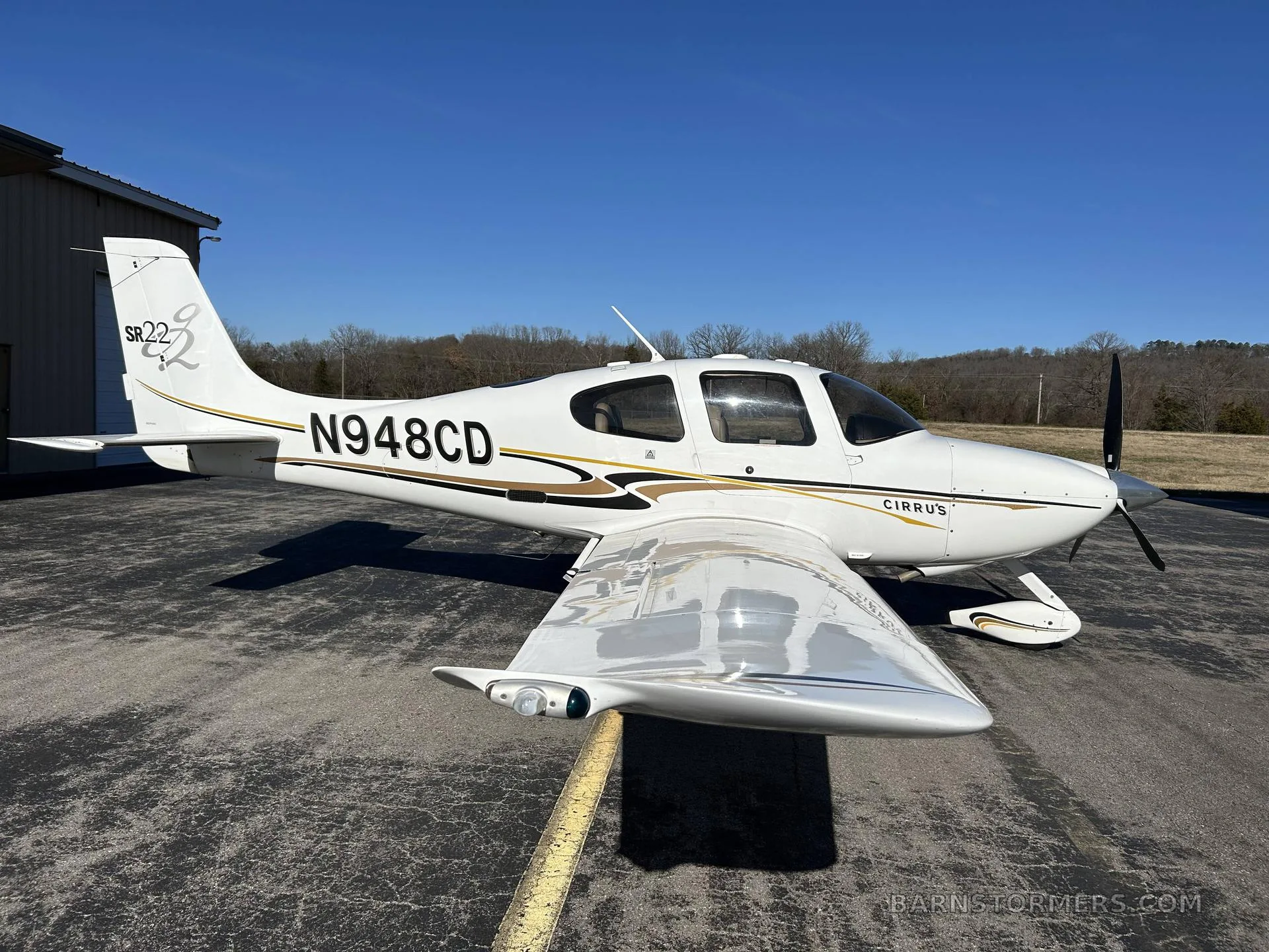
Free — save the SR22 G2 to your watchlist and track it in one place.
More Cirrus SR22 G2manuals & documents
- UMX Cirrus SR22T BNF BasicParts Catalog
- ForeFlight Performance Planning GuidePerformance Data
- AOPA PILOT / October 2021Service Bulletins
- PILOT’S OPERATING HANDBOOK AND FAA APPROVED AIRPLANE FLIGHT MANUAL for the CIRRUS DESIGN SR22Pilot's Operating Handbook
- Tornado Alley Turbo, Inc. TAT SB10-02, Rev. BService Bulletins
- TECHTALK • Cirrus sr20/sr22 MODel HistOry 1999-2007Service Bulletins
- Tornado Alley Turbo, Inc. TAT SB07-01Service Bulletins
- Supplemental Type CertificateType Certificate
- Cirrus Aircraft Maintenance ManualMaintenance Manual
If you fly the Cirrus SR22 G2, you may also be researching these.



In this document
Overview
The POH outlines the organization and purpose of the document, detailing the operating procedures for the S-TEC System Fifty Five X Autopilot in Cirrus SR20 and SR22 aircraft. It is crucial for pilots to carry this handbook during flights and to refer to the FAA-approved Aircraft Flight Manual for specific aircraft information.
Pre-Flight Procedures
This section details the necessary pre-flight checks, including the Power-Up Test and Pre-Flight Test. Pilots must verify the autopilot's functionality by following a series of actions and confirming the corresponding responses, ensuring that the autopilot is ready for operation.
In-Flight Procedures
The in-flight procedures cover the normal operating modes of the autopilot, including Heading (HDG) Mode, Navigation (NAV) Mode, and others. Each mode's activation process and operational details are explained, providing pilots with the necessary information to utilize the autopilot effectively during flight.
Operating Parameters
This section outlines the operational limits and parameters for the autopilot, including roll and pitch axis limits. Understanding these parameters is essential for safe autopilot operation.
Glossary
A glossary of terms used throughout the handbook, providing definitions and explanations to assist pilots in understanding the technical language related to the autopilot system.
Safety notes
- The autopilot should only be used in conjunction with the FAA-approved Aircraft Flight Manual or Supplement.
- Pilots should develop a thorough understanding of the autopilot's operating procedures before using it under IFR conditions.
Full document text
Cirrus SR20/22 Aircraft SR20: SN 1337 and Above SR22: SN 0435 and Above Pilot’s Operating Handbook 2nd Ed. Nov 15, 07 i S–TEC List of Effective Pages * Asterisk indicates pages changed, added, or deleted by current revision. Page No. Issue * 3-9 2 nd Ed, 1st Rev * 3-18 2 nd Ed, 1st Rev * 4-3 2 nd Ed, 1 st Rev Record of Revisions Retain this record in front of handbook. Upon receipt of a revision, insert changes and complete table below. Revision Number Revision Date Insertion Date/Initials 1 st Ed. Jul 15, 06 1 st Rev. Jul 19, 06 2 nd Rev. Aug 30, 06 2 nd Ed. Nov 15, 07 1 st Rev. Mar 01, 08 1st Rev. Mar 01, 08 ii 2nd Ed. Nov 15, 07 S–TEC Page Intentionally Blank 2nd Ed. Nov 15, 07 iii S–TEC Table of Contents Sec. Pg. 1 Overview...........................................................................................................1–1 1.1 Document Organization....................................................................1–3 1.2 Purpose..............................................................................................1–3 1.3 General Control Theory....................................................................1–3 1.4 Modes of Operation...........................................................................1–4 1.4.1 Roll Axis Control.................................................................1–4 1.4.2 Pitch Axis Control...............................................................1–4 1.5 Block Diagram....................................................................................1–4 2 Pre-Flight Procedures...................................................................................2–1 2.1 Power-Up Test....................................................................................2–3 2.2 Pre-Flight Test....................................................................................2–7 3 In-Flight Procedures......................................................................................3–1 3.1 Normal Operating Procedures........................................................3–3 3.1.1 Heading (HDG) Mode........................................................3–3 3.1.2 Navigation (NAV) Mode......................................................3–4 3.1.2.1 Pilot Selectable Intercept Angle........................3–7 3.1.3 Global Positioning System Steering (GPSS) Mode.......3–8 3.1.3.1 Pilot Selectable Intercept Angle.......................3–10 3.1.4 Altitude Hold (ALT) Mode..................................................3–11 3.1.5 Vertical Speed (VS) Mode.................................................3–12 3.1.5.1 Normal Operation..............................................3–12 3.1.5.2 PFD Failure Operation....................................3–12 iv 2nd Ed. Nov 15, 07 S–TEC 3.1.6 Altitude Pre-Select Function.............................................3–14 3.1.7 Autotrim (SR22 Only).......................................................3–16 3.1.8 Manual Electric Trim (SR22 Only)..................................3–16 3.2 Precision Approach Procedures.....................................................3–18 3.2.1 Straight-In ILS Approach....................................................3–18 3.2.2 ILS Approach with Procedure Turn................................3–22 3.3 Non-Precision Approach Procedures............................................3–22 3.3.1 Straight-In Back Course Approach..................................3–22 3.3.2 Back Course Approach with Procedure Turn...............3–24 3.3.3 Straight-In LOC Approach................................................3–26 3.3.4 Straight-In VOR Approach.................................................3–27 3.3.5 LOC Approach with Procedure Turn..............................3–28 3.3.6 VOR Approach with Procedure Turn..............................3–30 3.3.7 GPSS Approach (Lateral Guidance Only).....................3–32 3.4 Flight Director (FD) Operation.........................................................3–32 3.4.1 AP Mode...............................................................................3–32 3.4.2 FD Mode...............................................................................3–33 3.5 WAAS Procedures..............................................................................3–34 3.5.1 GPS Approach (With Vertical Guidance).......................3–34 3.5.2 Missed Approach................................................................3–34 3.6 Autopilot Disconnect ........................................................................3–34 4 Operating Parameters..................................................................................4–1 4.1 Roll Axis Limits..................................................................................4–3 4.2 Pitch Axis Limits.................................................................................4–3 5 Glossary...........................................................................................................5–1 2nd Ed. Nov 15, 07 v S–TEC List of Figures Fig. Pg. 1–1 System Fifty Five X Block Diagram..............................................................1–5 2–1 AP Display, Power-Up Annunciations........................................................2–4 2–2 AP Display, Software Revision Number.....................................................2–4 2–3 PFD Display, INITIAL AHRS ALIGNMENT Message.................................2–4 2–4 AP Display, RDY Annunciation....................................................................2–5 2–5 PFD Display, AP RDY Annunciation............................................................2–5 2–6 AP Display, FAIL Annunciation.....................................................................2–6 2–7 PFD Display, AP FAIL Annunciation.............................................................2–6
Show full textShow less
2–8 AP Display, HDG Mode Engaged (Pre-Flight) ..........................................2–8 2–9 PFD Display, HDG Mode Engaged (Pre-Flight)........................................2–8 2–10 AP Display, HDG and ALT HOLD Modes Engaged (Pre-Flight)..............2–9 2–11 PFD Display, HDG and ALT HOLD Modes Engaged (Pre-Flight)..........2–9 2–12 AP Display, HDG and VS Modes Engaged (Pre-Flight)..........................2–11 2–13 PFD Display, HDG and VS Modes Engaged (Pre-Flight).......................2–11 3–1 AP Display, HDG Mode Engaged................................................................3–3 3–2 PFD Display, HDG Mode Engaged.............................................................3–3 3–3 AP Display, NAV Mode Engaged..................................................................3–4 3–4 PFD Display, NAV Mode Engaged, A/C on 45° Intercept Angle...............3–4 3–5 PFD Display, NAV Mode Engaged, A/C Turning onto Course.................3–5 3–6 PFD Display, NAV Mode Engaged, A/C Tracking Course.........................3–6 3–7 AP Display, APR Mode Engaged .................................................................3–7 3–8 AP Display, HDG Mode Engaged, NAV Mode Armed................................3–7 vi 2nd Ed. Nov 15, 07 S–TEC 3–9 PFD Display, HDG Mode Engaged, NAV Mode Armed..............................3–8 3–10 AP Display, GPSS Mode Engaged..............................................................3–8 3–11 PFD Display, GPSS Mode Engaged...........................................................3–9 3–12 AP Display, HDG Mode Engaged, GPSS Mode Armed...........................3–10 3–13 PFD Display, HDG Mode Engaged, GPSS Mode Armed........................3–10 3–14 AP Display, HDG and ALT HOLD Modes Engaged.................................3–11 3–15 PFD Display, HDG and ALT HOLD Modes Engaged...............................3–11 3–16 AP Display, HDG and VS Modes Engaged..............................................3–13 3–17 PFD Display, HDG and VS Modes Engaged...........................................3–12 3–18 AP Display, HDG and VS Modes Engaged, PFD Failure........................3–13 3–19 AP Display, HDG and VS Modes Engaged, ALT HOLD Mode Armed....3–15 3–20 PFD Display, HDG and VS Modes Engaged, ALT HOLD Mode Armed....3–15 3–21 AP Display, HDG and ALT HOLD Modes Engaged.................................3–15 3–22 AP Display, HDG and ALT HOLD Modes Engaged, Autotrim in Progress.........3–16 3–23 AP Display, NAV, APR, and ALT HOLD Modes Engaged.......................3–19 3–24 PFD Display, NAV, APR, and ALT HOLD Modes Engaged .....................3–19 3–25 AP Display, NAV, APR and ALT HOLD Modes Engaged, GS Mode Armed .......3–20 3–26 PFD Display, NAV, APR and ALT HOLD Modes Engaged, GS Mode Armed......3–20 3–27 AP Display, NAV, APR and GS Modes Engaged......................................3–21 3–28 PFD Display, NAV, APR and GS Modes Engaged...................................3–21 3–29 Straight-In ILS Approach...............................................................................3–21 3–30 AP Display, APR Mode Engaged, Back Course......................................3–22 3–31 AP Display, APR Mode Engaged, Back Course......................................3–23 3–32 Straight-In Back Course Approach.............................................................3–23 2nd Ed. Nov 15, 07 vii S–TEC 3–33 AP Display, APR Mode Engaged, Track LOC Back Course Outbound.............3–24 3–34 AP Display, APR Mode Engaged, Track LOC Back Course Inbound................3–24 3–35 Back Course Approach with Procedure Turn..........................................3–25 3–36 AP Display, APR Mode Engaged, Track LOC Front Course Inbound..................3–26 3–37 Straight-In LOC Approach............................................................................3–26 3–38 AP Display, APR Mode Engaged, Track VOR Front Course Inbound.................3–27 3–39 Straight-In VOR Approach............................................................................3–27 3–40 AP Display, APR Mode Engaged, Track LOC Front Course Outbound .............3–28 3–41 AP Display, APR Mode Engaged, Track LOC Front Course Inbound...............3–28 3–42 LOC Approach with Procedure Turn........................................................3–29 3–43 AP Display, REV Mode Engaged, Track VOR Front Course Outbound.............3–30 3–44 AP Display, APR Mode Engaged, Track VOR Front Course Inbound...............3–30 3–45 VOR Approach with Procedure Turn........................................................3–31 3–46 PFD Display, HDG and ALT HOLD AP Modes Engaged.........................3–32 3–47 PFD Display, FD Mode Only Engaged.....................................................3–33 viii 2nd Ed. Nov 15, 07 S–TEC List of Tables Table Pg. 2–1 Power-Up Test...............................................................................................2–3 2–2 Pre-Flight Test...............................................................................................2–7 2nd Ed. Nov 15, 07 1-1 S–TEC SECTION 1 OVERVIEW 1-2 2nd Ed. Nov 15, 07 S–TEC Page Intentionally Blank 2nd Ed. Nov 15, 07 1-3 S–TEC 1.1 Document Organization Section 1 Overview Section 2 Pre-Flight Procedures Section 3 In-Flight Procedures Section 4 Operating Parameters Section 5 Glossary 1.2 Purpose This Pilot's Operating Handbook (POH) provides Pre-Flight and In-Flight operating procedures for the S-TEC System Fifty Five X Autopilot (AP), installed in the Cirrus SR20/22 aircraft (A/C), and integrated with the Avidyne Primary Flight Display (PFD), as well as the Garmin 400/500 Series or 400W/500W Series Navigation Receiver. Note: This POH must be carried in the A/C and made available to the pilot at all times. It can only be used in conjunction with the Federal Aviation Administration (FAA) approved Aircraft Flight Manual (AFM) or Aircraft Flight Manual Supplement (AFMS). Refer to the applicable AFM or AFMS for A/C specific information, such as unique ground tests, limitations, and emergency procedures. Note: The System Fifty Five X autopilot is a tool provided to Cirrus SR20/22 aircraft owners, that serves to assist them with cockpit workload management. The ability of the autopilot to provide optimum assistance and performance is directly proportional to the pilot's knowledge of its operating procedures. Therefore, it is highly recommended that the pilot develop a thorough understanding of the autopilot, its modes, and operating procedures in Visual Meteorological Conditions (VMC), prior to using it under Instrument Flight Rules (IFR). 1.3 General Control Theory The System Fifty Five X is a rate based autopilot. When in control of the roll axis, the autopilot senses turn rate, as well as closure rate to the selected course, along with the non-rate quantities of heading error, course error, and course deviation indication. When in control of the pitch axis, the autopilot senses vertical speed, acceleration, and closure rate to the selected glideslope, along with the non-rate quantities of altitude and glideslope deviation indication. These sensed data provide feedback to the autopilot, which processes them in order to control the aircraft through the use of mechanisms coupled to the control system. The roll trim cartridge is coupled to the ailerons. The pitch trim cartridge and pitch servo (selected aircraft only) are coupled to the elevator. Activation of roll axis control must always precede activation of pitch axis control. 1-4 2nd Ed. Nov 15, 07 S–TEC 1.4 Modes of Operation 1.4.1 Roll Axis Control Heading (HDG) Mode Used to Turn onto a Selected Heading and Hold it Navigation (NAV) Mode Used to Intercept and Track a VOR/GPS Course Approach (APR) Mode Used to Intercept and Track a LOC/GPS Front Course Inbound Reverse (REV) Mode Used to Intercept and Track a LOC Back Course Inbound Global Positioning System Steering (GPSS) Mode Used to Laterally Steer along a Course defined by GPS 1.4.2 Pitch Axis Control Altitude Hold (ALT) Mode Used to Hold Altitude Vertical Speed (VS) Mode Used to Hold Vertical Speed Glideslope (GS) Mode Used to Intercept and Track Glideslope Note: Glidepath can herein this document be used interchangeably with Glideslope. 1.5 Block Diagram The System Fifty Five X Block Diagram is shown in Fig. 1-1. 2nd Ed. Nov 15, 07 1-5 S–TEC Fig. 1-1. System Fifty Five X Block Diagram 1-6 2nd Ed. Nov 15, 07 S–TEC Page Intentionally Blank 2nd Ed. Nov 15, 07 2-1 S–TEC SECTION 2 PRE-FLIGHT PROCEDURES 2-2 2nd Ed. Nov 15, 07 S–TEC Page Intentionally Blank 2nd Ed. Nov 15, 07 2-3 S–TEC 2.1 Power-Up Test Perform the actions shown in Table 2-1. For each action, verify the corresponding response where applicable. Table 2-1. Power-Up Test ACTION RESPONSE 1. Set Battery Master Switch to ON position. All annunciations appear on AP display as shown in Fig. 2-1, and then extinguish. Software revision number briefly appears on AP display as shown in Fig. 2-2, and then extinguishes. INITIAL AHRS ALIGNMENT message appears on PFD display, as shown in Fig. 2-3. RDY annunciation alone re-appears on AP display within 3 minutes, as shown in Fig. 2-4 (Notes 1, 2). Once AHRS has completed its alignment, AP RDY annunciation appears on PFD display as shown in Fig. 2-5. Notes: 1. Should a failure be detected, the FAIL annunciation alone will re-appear on the AP display as shown in Fig. 2-6, and the autopilot will not operate. In addition, the AP FAIL annunciation will appear on the PFD, as shown in Fig. 2-7. 2. Should the rate gyro internal to the Turn Coordinator fail to reach sufficient speed, the AP display will remain blank indefinitely and the autopilot will not operate. This typically indicates that the Turn Coordinator needs repair. 2-4 2nd Ed. Nov 15, 07 S–TEC Fig. 2-1. AP Display, Power-Up Annunciations Fig. 2-2. AP Display, Software Revision Number Fig. 2-3. PFD Display, INITIAL AHRS ALIGNMENT Message 2nd Ed. Nov 15, 07 2-5 S–TEC Fig. 2-4. AP Display, RDY Annunciation Fig. 2-5. PFD Display, AP RDY Annunciation 2-6 2nd Ed. Nov 15, 07 S–TEC Fig. 2-7. PFD Display, AP FAIL Annunciation Fig. 2-6. AP Display, FAIL Annunciation 2nd Ed. Nov 15, 07 2-7 S–TEC ACTION RESPONSE 1. Move A/C Control Sidestick left and right, to sense its freedom of movement about roll axis. ------ 2. Set PFD Hdg Bug under Lubber Line. ------ 3. Press HDG mode selector switch to engage heading mode. HDG annunciation alone appears on AP display, as shown in Fig. 2-8. HDG annunciation appears on PFD display and Hdg Bug is magenta, as shown in Fig. 2-9. 4. Turn PFD Hdg Bug to the left side of Lubber Line. A/C Control Sidestick moves to the left. 5. Turn PFD Hdg Bug to the right side of Lubber Line. A/C Control Sidestick moves to the right. 6. Set PFD Hdg Bug under Lubber Line. A/C Control Sidestick Stops. 7. Move A/C Control Sidestick forward and aft, to sense its freedom of movement about pitch axis (A/C with Pitch Servo Only). ------ 8. Press ALT mode selector switch to engage altitude hold mode. ALT annunciation appears with HDG on AP display, as shown in Fig. 2-10. ALT annunciation appears with HDG on PFD display, along with AP in upper right-hand corner, as shown in Fig. 2-11. FD Steering Command Bars on PFD display appear and are magenta, as shown in Fig. 2-11. Table 2-2. Pre-Flight Test (continued on page 2-10) 2.2 Pre-Flight Test Prior to takeoff and with engine running, perform the actions shown in Table 2-2. For each action, verify the corresponding response where applicable. All actions pertaining to mode selector switches apply to the autopilot, and not the PFD. 2-8 2nd Ed. Nov 15, 07 S–TEC Fig. 2-8. AP Display, HDG Mode Engaged (Pre-Flight) Fig. 2-9. PFD Display, HDG Mode Engaged (Pre-Flight) 2nd Ed. Nov 15, 07 2-9 S–TEC Fig. 2-10. AP Display, HDG and ALT HOLD Modes Engaged (Pre-Flight) Fig. 2-11. PFD Display, HDG and ALT HOLD Modes Engaged (Pre-Flight) 2-10 2nd Ed. Nov 15, 07 S–TEC Table 2-2. Pre-Flight Test (continued from page 2-7) ACTION RESPONSE 9. Attempt movement of A/C Control Sidestick forward and aft (A/C with Pitch Servo Only). A/C Control Sidestick’s reduced freedom of movement indicates that Pitch Servo is engaged. Pitch Servo can be overridden. If not, disconnect autopilot and do not use. 10. Set PFD VSI Bug to 0 FPM. ------ 11. Press VS mode selector switch to engage vertical speed mode. VS annunciation appears with HDG on AP display, as shown in Fig. 2-12. VS annunciation appears with HDG on PFD display, and VSI bug is magenta as shown in Fig. 2-13. 12. Set PFD VSI Bug to 500 FPM climbing. A/C Control Sidestick moves in aft direction. 13. Set PFD VSI Bug to 500 FPM descending. A/C Control Sidestick moves in forward direction. 14. Set PFD VSI Bug to 0 FPM. A/C Control Sidestick stops. 15. Move A/C Control Sidestick as far aft as possible (A/C with Pitch Servo Only). After 3 seconds, TRIM ∨ annunciation appears on AP display. After 7 seconds, TRIM ∨ annunciation flashes. 16. Move A/C Control Sidestick as far forward as possible (A/C with Pitch Servo Only). After 3 seconds, TRIM ∧ annunciation appears on AP display. After 7 seconds, TRIM ∧ annunciation flashes. 17. Move A/C Control Sidestick aft until TRIM ∧ annunciation is extinguished (A/C with Pitch Servo Only). ------ 2nd Ed. Nov 15, 07 2-11 S–TEC Fig. 2-12. AP Display, HDG and VS Modes Engaged (Pre-Flight) Fig. 2-13. PFD Display, HDG and VS Modes Engaged (Pre-Flight) 2-12 2nd Ed. Nov 15, 07 S–TEC ACTION RESPONSE 18. Set PFD Alt Bug to higher altitude, and then engage Altitude Pre-Select Function by simultaneously pressing VS and ALT mode selector switches. A/C Control Sidestick moves in aft direction. ALT and VS annunciations appear on AP display. ALT and VS annunciations appear on PFD display. Alt Bug and VSI Bug on PFD display change to full magenta fill. Note: If ALT Bug or VSI Bug does not change to full magenta, or if no AP annunciation appears on PFD, then reset PFD circuit breakers, disconnect autopilot, and return to step 1. 19. Press Remote AP OFF / FD ON Switch. AP ON Switch annunciation is extinguished. AP OFF / FD ON Switch annunciation appears and is amber. FD annunciation appears on PFD display in upper right-hand corner, and is green. FD Steering Command Bars on PFD change to green. 20. Move A/C Control Sidestick forward and aft (A/C with Pitch Servo Only). A/C Control Sidestick’s freedom of movement indicates that Pitch Servo is disengaged. 21. Press ALT mode selector switch to engage altitude hold mode. ALT annunciation appears with HDG on AP display, and VS annunciation is extinguished. 22. Turn PFD Hdg Bug to the left side of Lubber Line. FD Steering Command Bars on PFD slowly move to a left turn position. 23. Turn PFD Hdg Bug to the right side of Lubber Line. FD Steering Command Bars on PFD slowly move to a right turn position. Table 2-2. Pre-Flight Test (continued from page 2-10) 2nd Ed. Nov 15, 07 2-13 S–TEC ACTION RESPONSE 24. Rotate Modifier Knob ½ turn CW. FD Steering Command Bars on PFD slowly move to a pitch up position. 25. Rotate Modifier Knob 1 turn CCW. FD Steering Command Bars on PFD slowly move to a pitch down position. 26. Press VS mode selector switch to reset Modifier Knob. ------ 27. Press forward and maintain pressure on Manual Electric Trim Switch (A/C with Pitch Servo Only). A/C trims nose down. 28. Release Manual Electric Trim Switch (A/C with Pitch Servo Only). A/C stops trimming. 29. Press aft and maintain pressure on Manual Electric Trim Switch (A/C with Pitch Servo Only). A/C trims nose up. 30. Release Manual Electric Trim Switch (A/C with Pitch Servo Only). A/C stops trimming. 31. Press Remote AP ON Switch to engage AP mode. AP OFF / FD ON Switch annunciation is extinguished. AP ON Switch annunciation appears and is green. FD annunciation on PFD changes to AP. FD Steering Command Bars on PFD change to magenta. 32. Attempt movement of A/C Control Sidestick forward and aft (A/C with Pitch Servo Only). A/C Control Sidestick’s reduced freedom of movement indicates that Pitch Servo is engaged. Table 2-2. Pre-Flight Test (continued from page 2-12) 2-14 2nd Ed. Nov 15, 07 S–TEC ACTION RESPONSE 33. Press AP DISC / TRIM INTR Switch, to disconnect autopilot. Note: RDY annunciation flashes and audible alert sounds a periodic tone, while all other annunciations are extinguished. Pressing and holding AP DISC / TRIM INTR Switch will limit audible alert to a single “beep”. After 5 seconds, RDY annunciation stops flashing but remains, and audible alert is squelched. FD Steering Command Bars on PFD are extinguished. 34. Trim A/C for takeoff. ------ Table 2-2. Pre-Flight Test (continued from page 2-13) 2nd Ed. Nov 15, 07 3-1 S–TEC SECTION 3 IN-FLIGHT PROCEDURES 3-2 2nd Ed. Nov 15, 07 S–TEC Page Intentionally Blank 2nd Ed. Nov 15, 07 3-3 S–TEC Fig. 3-2. PFD Display, HDG Mode Engaged Fig. 3-1. AP Display, HDG Mode Engaged 3.1 Normal Operating Procedures 3.1.1 Heading (HDG) Mode Set the PFD Hdg Bug to the desired heading on the compass card, and press the HDG mode selector switch to engage the heading mode. HDG annunciation will appear as shown in Fig. 3-1. The autopilot will turn the aircraft onto the selected heading and hold it. A new heading can be subsequently selected by setting the PFD Hdg Bug to the desired heading. A typical view of the PFD with the heading mode engaged is shown in Fig. 3-2. 3-4 2nd Ed. Nov 15, 07 S–TEC Fig. 3-3. AP Display, NAV Mode Engaged Fig. 3-4. PFD Display, NAV Mode Engaged, A/C on 45°°°°° Intercept Angle 3.1.2 Navigation (NAV) Mode Select a VOR frequency on the Navigation Receiver. Set the PFD CRS Pointer to the desired course on the compass card, and press the NAV mode selector switch to engage the navigation mode. The NAV annunciation will appear as shown in Fig. 3-3. If the Left/Right Needle is at full scale (100%) deflection from center, the autopilot will establish the aircraft on a 45° intercept angle relative to the selected course. If the Left/Right Needle is less than 100% deflection from center, the autopilot may still establish an intercept angle of 45°, provided the aircraft's closure rate to the selected course is sufficiently slow. Otherwise, the intercept angle will be less than 45°. A typical view of the PFD during this stage of the intercept sequence is shown in Fig. 3-4. 2nd Ed. Nov 15, 07 3-5 S–TEC As the aircraft approaches the selected course, the autopilot will sense the corresponding rate at which the Left/Right Needle approaches center (closure rate), and gradually shallow the intercept angle as the autopilot turns the aircraft onto the course. A typical view of the PFD during this stage of the intercept sequence is shown in Fig. 3-5. The point at which this turn begins is variable, depending upon the closure rate. Although closure rate is principally a function of airspeed, the distance of the aircraft from the ground station also has an effect. However, the turn will always begin between 100% and 20% of Left/ Right Needle deflection from center, or Course Deviation Indication (CDI). During this stage of the intercept sequence, the autopilot operates at maximum gain and sensitivity to closure rate. In addition, the autopilot will limit the aircraft's turn rate to 90% of a standard rate turn. When the aircraft arrives at 15% CDI needle deflection, the course is captured. At course capture, a step reduction in autopilot gain occurs; however, the PFD CRS Pointer has sufficient authority to complete the intercept. In addition, the sensitivity to closure rate is reduced. The overall authority of the autopilot during this stage of the intercept sequence is called the HIGH GAIN condition. Fifteen seconds after course capture, a second step reduction in autopilot gain occurs, and will limit the aircraft's turn rate to 45% of a standard rate turn. In addition, the sensitivity to closure rate is reduced again. The overall authority of the autopilot during this stage of the intercept sequence is called the INTERMEDIATE GAIN condition. Fig. 3-5. PFD Display, NAV Mode Engaged, A/C Turning onto Course 3-6 2nd Ed. Nov 15, 07 S–TEC Thirty seconds after course capture, the autopilot will establish the required crosswind correction angle. Seventy five seconds after course capture, a third step reduction in autopilot gain occurs to limit the aircraft's turn rate to 15% of a standard rate turn. In addition, the sensitivity to closure rate is reduced once more. The overall authority of the autopilot during this final stage of the intercept sequence is called the LOW GAIN condition. This marks the end of the intercept sequence, and the beginning of tracking. A typical view of the PFD during tracking is shown in Fig. 3-6. The pilot should make speed, distance, and time considerations during the 75 second period from course capture to the beginning of tracking, to account for the aircraft's position. For example at 115 kts, a distance of 2.4 nautical miles will be traveled in 75 seconds. If PFD CRS Pointer is within 5° of the selected course, and the CDI needle deflection is less than 10%, the autopilot will immediately establish the LOW GAIN condition upon engagement of the NAV mode. While tracking in the LOW GAIN condition, the autopilot ignores short term CDI needle excursions, to thereby inhibit aircraft scalloping during VOR station passage. Should the CDI needle deflection exceed 50% for a period of 60 seconds, the autopilot will revert to the INTERMEDIATE GAIN condition, as a means to re-establish the aircraft on course. Fig. 3-6. PFD Display, NAV Mode Engaged, A/C Tracking Course 2nd Ed. Nov 15, 07 3-7 S–TEC The NAV annunciation will flash whenever the CDI needle deflection exceeds 50%, or the NAV Flag is in view. In the latter event, the FAIL annunciation will also appear. While tracking in the LOW GAIN condition and within 50% CDI needle deflection, to track in the higher authority INTERMEDIATE GAIN condition, press the APR mode selector switch to engage the approach mode. This is acknowledged as shown in Fig. 3-7. While tracking in either the LOW GAIN or INTERMEDIATE GAIN condition, if a new course is selected that is different from the original course by 10° or more, the autopilot will revert to the HIGH GAIN condition. Fig. 3-7. AP Display, APR Mode Engaged 3.1.2.1 Pilot Selectable Intercept Angle To select an intercept angle other than 45°, set the PFD Hdg Bug to the desired intercept heading on the compass card, such that the difference between this heading and the desired course is the intercept angle. Set the PFD CRS Pointer to the desired course. Press and hold the HDG mode selector switch, and press the NAV mode selector switch to engage the heading mode and arm the navigation mode. HDG and NAV annunciations will appear as shown in Fig. 3-8. The autopilot will establish the aircraft on the selected intercept angle (heading). A typical view of the PFD during this stage of the intercept sequence is shown in Fig. 3-9. The autopilot will hold this heading until the autopilot must turn the aircraft onto the selected course, to prevent overshoot. At this point in the intercept sequence, the HDG annunciation will extinguish to indicate engagement of the navigation mode. Fig. 3-8. AP Display, HDG Mode Engaged, NAV Mode Armed 3-8 2nd Ed. Nov 15, 07 S–TEC Fig. 3-9. PFD Display, HDG Mode Engaged, NAV Mode Armed 3.1.3 Global Positioning System Steering (GPSS) Mode The GPSS mode should be used anytime the selected navigation source is the Global Positioning System (GPS). Engagement of the GPSS mode requires pressing the NAV mode selector switch twice, unless the NAV mode is engaged. If the NAV mode is engaged, press the NAV mode selector switch once to engage the GPSS mode. The NAV and GPSS annunciations will appear as shown in Fig. 3-10. Fig. 3-10. AP Display, GPSS Mode Engaged 2nd Ed. Nov 15, 07 3-9 S–TEC The autopilot will laterally steer the aircraft along a predefined course programmed into the Navigation Receiver, and limit its turn rate to either: 130% of a standard rate turn (Prog/Comp Hardware Mod Code AM and below) 90% of a standard rate turn (Prog/Comp Hardware Mod Code AN and AP) 110% of a standard rate turn (Prog/Comp Hardware Mod Code AR and above) During the GPSS mode of operation, the autopilot will not accept any course error input from the PFD CRS Pointer. A typical view of the PFD with the GPSS mode engaged is shown in Fig. 3-11. Fig. 3-11. PFD Display, GPSS Mode Engaged If there are no programmed course segments in the Navigation Receiver upon attempted engagement of the GPSS mode, the FAIL annunciation will appear, NAV and GPSS annunciations will flash, and the autopilot will hold the aircraft's wings level. With the GPSS mode engaged, the autopilot is also capable of executing the following procedures if programmed into the Navigation Receiver: Procedure Turns, Approaches, Missed Approaches, Holding Patterns However, the autopilot will not automatically fly vertical profiles (reference section 3.5.2). 1st Rev. Mar 01, 08 3-10 2nd Ed. Nov 15, 07 S–TEC Fig. 3-12. AP Display, HDG Mode Engaged, GPSS Mode Armed The autopilot will establish the aircraft on the selected intercept angle (heading). A typical view of the PFD during this stage of the intercept sequence is shown in Fig. 3-13. The autopilot will hold this heading until the autopilot must turn the aircraft onto the course segment to prevent overshoot. At this point in the intercept sequence, the HDG annunciation will extinguish to indicate engagement of the GPSS mode. Fig. 3-13. PFD Display, HDG Mode Engaged, GPSS Mode Armed 3.1.3.1 Pilot Selectable Intercept Angle To select a course intercept angle, set the PFD Hdg Bug to the desired intercept heading on the compass card, such that the difference between this heading and the next course segment is the intercept angle. Press and hold the HDG mode selector switch, and press the NAV mode selector switch twice to engage the HDG mode and arm the GPSS mode. HDG, NAV, and GPSS annunciations will appear as shown in Fig. 3-12. 2nd Ed. Nov 15, 07 3-11 S–TEC 3.1.4 Altitude Hold (ALT) Mode The altitude hold mode can only be engaged if a roll mode (HDG, NAV, APR, GPSS, REV) is engaged. With a roll mode engaged and the aircraft at the desired altitude, press the ALT mode selector switch to engage the altitude hold mode. The ALT annunciation will appear as shown in Fig. 3-14. The autopilot will hold the aircraft at its current absolute pressure altitude. The captured altitude may be modified for barometric pressure changes by rotating the Modifier Knob either clockwise (CW) for an increase in altitude, or counter- clockwise (CCW) for a decrease in altitude. Each detent equals 20 feet, and the range is ±360 feet from the original captured altitude. A typical view of the PFD with the altitude hold mode engaged is shown in Fig. 3-15. Engagement of the altitude hold mode will reset the PFD Alt Bug to the captured altitude. Fig. 3-14. AP Display, HDG and ALT HOLD Modes Engaged Fig. 3-15. PFD Display, HDG and ALT HOLD Modes Engaged 3-12 2nd Ed. Nov 15, 07 S–TEC 3.1.5 Vertical Speed (VS) Mode Caution: The vertical speed mode may be used for establishing and maintaining a PILOT selected vertical speed. The autopilot receives no airspeed information; therefore, it is the responsibility of the pilot to manage the vertical speed selection within the operating limits of the aircraft's capabilities. Selection of a vertical speed outside the capability of the aircraft can create a condition of reduced airspeed, and possibly lead to an aircraft stall condition. 3.1.5.1 Normal Operation The vertical speed mode can only be engaged if a roll mode (HDG, NAV, APR, GPSS, REV) is engaged. With a roll mode engaged, set the PFD VSI Bug to the desired vertical speed, and press the VS mode selector switch to engage the vertical speed mode. The VS annunciation will appear as shown in Fig. 3-16. If within the aircraft's capabilities, the autopilot will attain and hold the aircraft at the vertical speed for which the VSI Bug is set. A typical view of the PFD with the heading and vertical speed modes engaged is shown in Fig. 3-17. During a climb, should the aircraft become unable to hold the commanded vertical speed for a period of fifteen seconds, the VS annunciation will flash as an alert to the potential for an impending stall condition. In this event, immediately increase the aircraft's thrust if possible, reduce the commanded vertical speed using the PFD VSI Bug, or both, until the VS annunciation stops flashing. Note: In the event of a PFD failure, refer to paragraph 3.1.5.2 for operation of the vertical speed mode. 3.1.5.2 VS Mode Operation during PFD Failure The vertical speed mode can only be engaged if a roll mode (HDG, NAV, APR, GPSS, REV) is engaged. With a roll mode engaged, press the VS mode selector switch to engage the vertical speed mode. VS and current vertical speed annunciations will appear on the autopilot display, as shown in Fig. 3-18. The current vertical speed appears as a number in units of FPM x 100, along with either a "+" prefix to indicate a climb, or a "-" prefix to indicate a descent (i.e., for example, +5 indicates 500 FPM climbing if within the aircraft's capabilities). The autopilot will hold the aircraft at its current vertical speed. The vertical speed may be modified by rotating the Modifier Knob. In a climb, rotating the Modifier Knob clockwise (CW) increases the climb rate, whereas rotating it counter- clockwise (CCW) decreases the climb rate. In a descent, rotating the Modifier Knob CCW increases the descent rate, whereas rotating it CW decreases the descent rate. Each detent equals 100 FPM, and the range is ±1600 FPM. 2nd Ed. Nov 15, 07 3-13 S–TEC Fig. 3-16. AP Display, HDG and VS Modes Engaged Fig. 3-17. PFD Display, HDG and VS Modes Engaged Fig. 3-18. AP Display, HDG and VS Modes Engaged, PFD Failure 3-14 2nd Ed. Nov 15, 07 S–TEC 3.1.6 Altitude Pre-Select Function The Altitude Pre-Select Function allows the pilot to pre-select a target altitude and the vertical speed (if within the aircraft's capabilities) at which the aircraft will climb or descend, until that altitude is captured. Engage a roll mode (HDG, NAV, APR, GPSS, REV). Set the PFD Alt Bug to the target altitude and the PFD VSI Bug to an acceptable vertical speed. Press and hold the VS mode selector switch, and press the ALT mode selector switch to engage the vertical speed mode and arm the altitude hold mode. ALT and VS annunciations will appear as shown in Fig. 3-19. If within the aircraft's capabilities, the autopilot will attain and hold the aircraft at the vertical speed for which the VSI Bug is set. A typical view of the PFD with the autopilot in this configuration is shown in Fig. 3-20. As the aircraft approaches the target altitude, a scheduled reduction in the vertical speed will automatically occur to ensure that there is no adverse acceleration at the point of capture. Once the target altitude has been captured, the VS annunciation will extinguish to indicate engagement of the ALT mode, as shown in Fig. 3-21. Note: Prior to altitude capture, with the VS mode engaged and the ALT mode armed, the PFD VSI Bug and/or PFD Alt Bug can be changed at any time, causing the autopilot to respond accordingly. Note: During the pre-select sequence, with the VS mode engaged and the ALT mode armed, the following are subject to occur: 1. Pressing the ALT mode selector switch once will disengage the VS mode, and engage the ALT mode. Consequently, the VS annunciation will extinguish, the PFD VSI Bug will reset to 0 FPM, and the Alt Bug will reset to the captured altitude. Finally, this may cause some adverse acceleration, as the autopilot works to hold the aircraft at the captured altitude. 2. Pressing the VS mode selector switch once will disarm the ALT mode, but leave the VS mode engaged. Consequently, the ALT annunciation will extinguish. 2nd Ed. Nov 15, 07 3-15 S–TEC Fig. 3-21. AP Display, HDG and ALT HOLD Modes Engaged Fig. 3-19. AP Display, HDG and VS Modes Engaged, ALT HOLD Mode Armed Fig. 3-20. PFD Display, HDG and VS Modes Engaged, ALT HOLD Mode Armed 3-16 2nd Ed. Nov 15, 07 S–TEC Fig. 3-22. AP Display, HDG and ALT HOLD Modes Engaged, Autotrim in Progress 3.1.8 Manual Electric Trim A Remote Manual Electric Trim Switch is located on each Control Sidestick. It can only be used to trim the aircraft from the RDY, or when the Remote AP OFF / FD ON Switch has been selected. To trim the aircraft nose up, press aft and maintain pressure on the Remote Manual Electric Trim Switch. To trim the aircraft nose down, press forward and maintain pressure on the Remote Manual Electric Trim Switch. 3.1.7 Autotrim (A/C with Pitch Servo Only) When the Remote AP ON Switch has been selected (reference section 3.4.1), and both a roll mode (HDG, NAV, APR, REV, GPSS) and a pitch mode (ALT, VS, GS) are engaged, the autopilot will provide an annunciation whenever it is automatically trimming the aircraft. A pitch mode can only be engaged after a roll mode has been engaged. Should the pitch servo loading exceed a preset threshold for a period of three seconds, the autopilot will annunciate either Trim ∧ or Trim ∨ as an advisement that the autopilot is automatically trimming the aircraft in the indicated direction. This is shown in Fig. 3-22. If the autopilot is still in the process of automatically trimming the aircraft after four more seconds, the annunciation will flash. When the aircraft has been sufficiently trimmed, such that the pitch servo loading is below the preset threshold, the annunciation will extinguish. 2nd Ed. Nov 15, 07 3-17 S–TEC Page Intentionally Blank 3-18 2nd Ed. Nov 15, 07 S–TEC 3.2 Precision Approach Procedures 3.2.1 Straight-In ILS Approach Execute a straight-in intercept and track of the FRONT INBOUND LOC course (reference section 3.3.3), while holding the approach altitude. The NAV, APR, and ALT annunciations will appear as shown in Fig. 3-23. A typical view of the PFD during this stage of the ILS approach sequence is shown in Fig. 3-24. The GS mode must be armed prior to engagement. Once the following conditions have existed simultaneously for a period of one second, the GS annunciation will appear to acknowledge that the GS mode has automatically armed, as shown in Fig. 3-25: 1. APR mode engaged 2. ALT mode engaged 3. NAV Flag out of view 4. GS Flag out of view 5. LOC frequency channeled 6. A/C within 50% needle deflection of LOC centerline 7. A/C more than 10% needle deflection below GS centerline A typical view of the PFD during this stage of the ILS approach sequence is shown in Fig. 3-26. The armed GS mode can be subsequently disabled by pressing the APR mode selector switch. The GS annunciation will flash to acknowledge this. To then re-arm the GS mode, press the APR mode selector switch again. The GS annunciation will immediately extinguish, but re-appear after 1 second. With the GS mode armed, once the aircraft arrives at 5% below the GS centerline, the ALT annunciation will extinguish to indicate engagement of the GS mode, as shown in Fig. 3-27. This marks the end of the intercept sequence, and the beginning of tracking. A typical view of the PFD during this stage of the ILS approach sequence is shown in Fig. 3-28. Note: If the approach positions the aircraft slightly above the GS centerline, press the ALT mode selector switch to immediately engage the GS mode. Caution: Manual engagement of the glideslope mode above the glideslope will result in the aircraft aggressively moving toward the glideslope. DO NOT manually engage the glideslope mode if the aircraft is more than 20% above the glideslope. 1st Rev. Mar 01, 08 2nd Ed. Nov 15, 07 3-19 S–TEC Fig. 3-23. AP Display, NAV, APR, and ALT HOLD Modes Engaged Fig. 3-24. PFD Display, NAV, APR, and ALT HOLD Modes Engaged The GS annunciation will flash whenever the Glideslope Deviation Indication (GDI) needle deflection exceeds 50%, or the GS Flag is in view. In the latter event, the FAIL annunciation will also appear. At the Decision Height (DH) or Missed Approach Point (MAP), disconnect the autopilot to execute either a manual landing or go-around, respectively. A pictorial of this procedure is shown in Fig. 3-29. 3-20 2nd Ed. Nov 15, 07 S–TEC Fig. 3-25. AP Display, NAV, APR and ALT HOLD Modes Engaged, GS Mode Armed Fig. 3-26. PFD Display, NAV, APR, and ALT HOLD Modes Engaged, GS Mode Armed 2nd Ed. Nov 15, 07 3-21 S–TEC Fig. 3-29. Straight-In ILS Approach Fig. 3-27. AP Display, NAV, APR, and GS Modes Engaged Fig. 3-28. PFD Display, NAV, APR, and GS Modes Engaged 3-22 2nd Ed. Nov 15, 07 S–TEC 3.2.2 ILS Approach with Procedure Turn Execute a procedure turn intercept and track of the FRONT INBOUND LOC course (reference section 3.3.5) above the approach altitude, just until the aircraft is established on the FRONT INBOUND PROCEDURE TURN heading, with the HDG mode still engaged. Set the PFD VSI Bug to the desired vertical descent speed, and press the VS mode selector switch to engage the VS mode. Upon reaching the approach altitude, press the ALT mode selector switch to engage the altitude hold mode. Press the NAV mode selector switch to engage the APR mode, such that the autopilot will execute a straight-in intercept and track of the FRONT INBOUND LOC course (reference section 3.3.3). Execute a straight-in intercept and track of the GS (reference section 3.2.1). With the GPSS mode engaged, the autopilot is capable of executing this entire approach sequence if it is programmed into the Navigation Receiver. Once inbound, with the conditions of section 3.2.1 satisfied and the Navigation Receiver set to VLOC, engage the APR mode to complete the ILS approach. 3.3 Non-Precision Approach Procedures 3.3.1 Straight-In Back Course Approach Select the LOC frequency on the Navigation Receiver. Set the PFD CRS Pointer to the FRONT INBOUND LOC course on the compass card. Press the REV mode selector switch to engage the APR mode. REV and APR annunciations will appear as shown in Fig. 3-30. The autopilot will intercept and track the BACK INBOUND LOC course. A typical view of the PFD during tracking is shown in Fig. 3-31. Fig. 3-30. AP Display, APR Mode Engaged, Back Course The REV annunciation will flash whenever the CDI needle deflection exceeds 50%, or the NAV Flag is in view. In the latter event, the FAIL annunciation will also appear. A summary pictorial of this procedure is shown in Fig. 3-32. 2nd Ed. Nov 15, 07 3-23 S–TEC Fig. 3-31. AP Display, APR Mode Engaged, Back Course a. Select LOC frequency. b. Set PFD CRS Pointer to FRONT INBOUND LOC course. c. Press REV mode selector switch to engage APR mode. d. Intercept and track BACK INBOUND LOC course. Fig. 3-32. Straight-In Back Course Approach 265° 085° Back Course 310° N 3-24 2nd Ed. Nov 15, 07 S–TEC 3.3.2 Back Course Approach with Procedure Turn Select the LOC frequency on the Navigation Receiver. Set the PFD CRS Pointer to the FRONT INBOUND LOC course on the compass card. Press the NAV mode selector switch to engage the APR mode. NAV and APR annunciations will appear as shown in Fig. 3-33. The autopilot will intercept and track the BACK OUTBOUND LOC course. Fig. 3-33. AP Display, APR Mode Engaged, Track LOC Back Course Outbound At the appropriate time, set the PFD Hdg Bug to the BACK OUTBOUND PROCEDURE TURN heading, and press the HDG mode selector switch to engage the heading mode. Hold this heading until the point at which it is time to turn the aircraft again. At that point, turn the PFD Hdg Bug in two successive 90° increments, to establish the aircraft on the BACK INBOUND PROCEDURE TURN heading. Press the REV mode selector switch to engage the APR mode. REV and APR annunciations will appear as shown in Fig. 3-34. The autopilot will intercept and track the BACK INBOUND LOC course. A summary pictorial of this procedure is shown in Fig. 3-35. For 400W/500W Series equipped aircraft, with the GPSS mode engaged, the autopilot is capable of executing this entire approach sequence if it is programmed into the Navigation Receiver. Once on the BACK INBOUND LOC course (subsequent to position 3 in Fig. 3-35) and with the Navigation Receiver set to VLOC, engage the REV mode to complete the back course approach. Fig. 3-34. AP Display, APR Mode Engaged, Track LOC Back Course Inbound 2nd Ed. Nov 15, 07 3-25 S–TEC 1. a. Select LOC frequency. b. Set PFD CRS Pointer to FRONT INBOUND LOC course. c. Press NAV mode selector switch to engage APR mode. d. Intercept and track BACK OUTBOUND LOC course. 2. a. At the appropriate time, set PFD Hdg Bug to BACK OUTBOUND PROCEDURE TURN heading. b. Press HDG mode selector switch to engage heading mode. 3. a. Turn PFD Hdg Bug in two successive 90° increments, to establish aircraft on BACK INBOUND PROCEDURE TURN heading. b. Press REV mode selector switch to engage APR mode. c. Intercept and track BACK INBOUND LOC course. Fig. 3-35. Back Course Approach with Procedure Turn 265° N 085° 310° 130° 1. 2. Back Course 3-26 2nd Ed. Nov 15, 07 S–TEC 1. a. Select LOC frequency. b. Set PFD CRS Pointer to FRONT INBOUND LOC course. c. Press NAV mode selector switch to engage APR mode. d. Intercept and track FRONT INBOUND LOC course. 2. a. At middle marker, if missed approach is declared, disconnect autopilot. b. Stabilize aircraft. c. Set PFD Hdg Bug to missed approach heading. d. Press HDG mode selector switch to engage heading mode. Fig. 3-37. Straight-In LOC Approach Fig. 3-36. AP Display, APR Mode Engaged, Track LOC Front Course Inbound 3.3.3 Straight-In LOC Approach Select the LOC frequency on the Navigation Receiver. Set the PFD CRS Pointer to the FRONT INBOUND LOC course on the compass card. Press the NAV mode selector switch to engage the APR mode. NAV and APR annunciations will appear as shown in Fig. 3-36. The autopilot will intercept and track the FRONT INBOUND LOC course. A summary pictorial of this procedure is shown in Fig. 3-37. 2nd Ed. Nov 15, 07 3-27 S–TEC 3.3.4 Straight-In VOR Approach Select the VOR frequency on the Navigation Receiver. Set the PFD CRS Pointer to the FRONT INBOUND VOR course on the compass card. Press the APR mode selector switch to engage the APR mode. NAV and APR annunciations will appear as shown in Fig. 3-38. The autopilot will intercept and track the FRONT INBOUND VOR course. Fig. 3-38. AP Display, APR Mode Engaged, Track VOR Front Course Inbound A summary pictorial of this procedure is shown in Fig. 3-39. 1. a. Select VOR frequency. b. Set PFD CRS Pointer to FRONT INBOUND VOR course. c. Press APR mode selector switch to engage approach mode. d. Intercept and track FRONT INBOUND VOR course. 2. a. At middle marker, if missed approach is declared, disconnect autopilot. b. Stabilize aircraft. c. Set PFD Hdg Bug to missed approach heading. d. Press HDG mode selector switch to engage heading mode. Fig. 3-39. Straight-In VOR Approach 3-28 2nd Ed. Nov 15, 07 S–TEC 3.3.5 LOC Approach with Procedure Turn Select the LOC frequency on the Navigation Receiver. Set the PFD CRS Pointer to the FRONT INBOUND LOC course on the compass card. Press the REV mode selector switch to engage the APR mode. REV and APR annunciations will appear as shown in Fig. 3-40. The autopilot will intercept and track the FRONT OUTBOUND LOC course. Fig. 3-40. AP Display, APR Mode Engaged, Track LOC Front Course Outbound At the appropriate time, set the PFD Hdg Bug to the FRONT OUTBOUND PROCEDURE TURN heading. Press the HDG mode selector switch to engage the heading mode. Hold this heading until the point at which it is time to turn the aircraft again. At that point, turn the PFD Hdg Bug in two successive 90° increments, to establish the aircraft on the FRONT INBOUND PROCEDURE TURN heading. Press the NAV mode selector switch to engage the APR mode. NAV and APR annunciations will appear as shown in Fig. 3-41. The autopilot will intercept and track the FRONT INBOUND LOC course. Fig. 3-41. AP Display, APR Mode Engaged, Track LOC Front Course Inbound A summary pictorial of this procedure is shown in Fig. 3-42. For 400W/500W Series equipped aircraft, with the GPSS mode engaged, the autopilot is capable of executing this entire approach sequence if it is programmed into the Navigation Receiver. Once on the FRONT INBOUND LOC course (subsequent to position 4 in Fig. 3-42) and with the Navigation Receiver set to VLOC, engage the APR mode to complete the front course approach. 2nd Ed. Nov 15, 07 3-29 S–TEC Fig. 3-42. LOC Approach with Procedure Turn 1. a. Select LOC frequency. b. Set PFD CRS Pointer to FRONT INBOUND LOC course. c. Press REV mode selector switch to engage APR mode. d. Intercept and track FRONT OUTBOUND LOC course. 2. a. At the appropriate time, set PFD Hdg Bug to FRONT OUTBOUND PROCEDURE TURN heading. b. Press HDG mode selector switch to engage heading mode. 3. a. Turn PFD Hdg Bug in two successive 90° increments, to establish aircraft on FRONT INBOUND PROCEDURE TURN heading. 4. a. Press NAV mode selector switch to engage approach mode. b. Intercept and track FRONT INBOUND LOC course. c. At middle marker, if missed approach is declared, disconnect autopilot. d. Stabilize aircraft. e. Set PFD Hdg Bug to missed approach heading. f. Press HDG mode selector switch to engage heading mode. N 3. 4. 310° 130° 3-30 2nd Ed. Nov 15, 07 S–TEC 3.3.6 VOR Approach with Procedure Turn Select the VOR frequency on the Navigation Receiver. Set the PFD CRS Pointer to the FRONT INBOUND VOR course on the compass card. Press the REV mode selector switch to engage the REV mode. The REV annunciation will appear as shown in Fig. 3-43. The autopilot will intercept and track the FRONT OUTBOUND VOR course. Fig. 3-43. AP Display, REV Mode Engaged, Track VOR Front Course Outbound At the appropriate time, set the PFD Hdg Bug to the FRONT OUTBOUND PROCEDURE TURN heading. Press the HDG mode selector switch to engage the heading mode. Hold this heading until the point at which it is time to turn the aircraft again. At that point, turn the PFD Hdg Bug in two successive 90° increments, to establish the aircraft on the FRONT INBOUND PROCEDURE TURN heading. Press the APR mode selector switch to engage the APR mode. NAV and APR annunciations will appear as shown in Fig. 3-44. The autopilot will intercept and track the FRONT INBOUND VOR course. Fig. 3-44. AP Display, APR Mode Engaged, Track VOR Front Course Inbound A summary pictorial of this procedure is shown in Fig. 3-45. For 400W/500W Series equipped aircraft, with the GPSS mode engaged, the autopilot is capable of executing this entire approach sequence if it is programmed into the Navigation Receiver. Once on the FRONT INBOUND VOR course (subsequent to position 4 in Fig. 3-45) and with the Navigation Receiver set to VLOC, engage the APR mode to complete the front course approach. 2nd Ed. Nov 15, 07 3-31 S–TEC 1. a. Select VOR frequency. b. Set PFD CRS Pointer to FRONT INBOUND VOR course. c. Press REV mode selector switch to engage REV mode. d. Intercept and track FRONT OUTBOUND VOR course. 2. a. At the appropriate time, set PFD Hdg Bug to FRONT OUTBOUND PROCEDURE TURN heading. b. Press HDG mode selector switch to engage heading mode. 3. a. Turn PFD Hdg Bug in two successive 90° increments, to establish aircraft on FRONT INBOUND PROCEDURE TURN heading. 4. a. Press APR mode selector switch to engage APR mode. b. Intercept and track FRONT INBOUND VOR course. c. At middle marker, if missed approach is declared, disconnect autopilot. d. Stabilize aircraft. e. Set PFD Hdg Bug to missed approach heading. f. Press HDG mode selector switch to engage heading mode. Fig. 3-45. VOR Approach with Procedure Turn N 3. 4. 310° 130° 3-32 2nd Ed. Nov 15, 07 S–TEC 3.3.7 GPSS Approach (Lateral Guidance Only) Press the NAV mode selector switch twice to engage the GPSS mode (reference section 3.1.3). The autopilot will laterally steer the aircraft along a predefined approach, which has been programmed into the Navigation Receiver. To control the assigned altitudes and rates of descent, use the Altitude Pre-Select Function (reference section 3.1.6). For 400/500 Series equipped aircraft, to make any procedure turns, engage the heading mode and use the PFD Hdg Bug (reference section 3.1.1). Upon completion, re-engage the GPSS mode. 3.4 Flight Director (FD) Operation The FD is a display of the flight profile. It is commanded by the autopilot. A pair of Steering Command Bars and an Aircraft Reference Symbol (ARS), superimposed upon a pitch ladder, comprise the FD. The FD operates in the AP mode or the FD mode. Although the ARS is always yellow, the color of the Steering Command Bars is different for each mode of operation. 3.4.1 AP Mode Press the Remote AP ON Switch, and engage a roll and pitch AP mode. In this case, the Steering Command Bars are magenta. The autopilot steers the aircraft toward the Steering Command Bars until the ARS is tucked into them. The FD provides a visual indication of how accurately the autopilot is tracking the roll and pitch commands. A typical view of the PFD while in AP mode is shown in Fig. 3-46. Fig. 3-46. PFD Display, HDG and ALT HOLD AP Modes Engaged 2nd Ed. Nov 15, 07 3-33 S–TEC 3.4.2 FD Mode Press the Remote AP OFF / FD ON Switch, and engage a roll and pitch mode to enable the FD mode. In this case, the Steering Command Bars are green. The pilot must steer the aircraft toward the Steering Command Bars, until the ARS is tucked into them. The FD provides a visual indication of how accurately the pilot is tracking the autopilot's roll and pitch commands. A typical view of the PFD in FD only mode is shown in Fig. 3-47. Fig. 3-47. PFD Display, FD Only Mode Engaged 3-34 2nd Ed. Nov 15, 07 S–TEC 3.5 WAAS Procedures 3.5.1 GPS Approach (With Vertical Guidance) For 400W/500W Series equipped aircraft, when conducting a WAAS approach, if the GPSS mode remains engaged, then the autopilot will execute the entire lateral procedure automatically (i.e., intercept and track front outbound course, complete procedure turn, intercept and track front inbound course). For 400W/500W Series equipped aircraft, the autopilot will follow the vertical commands sent from the PFD. The vertical approaches the autopilot will follow include: 1. LPV approaches (precision and LNAV/VNAV) 2. LNAV+V approaches (non-precision) Note: LPV approaches require the appropriate approved equipment. In order to intercept and fly the GPS generated glidepath, the autopilot must be in APR mode once the final approach course has been intercepted. The approach should be flown like a straight-in ILS (reference 3.2.1). Caution: The autopilot will not automatically level off at DH or MDA. The pilot must maintain awareness of altitude, and disconnect the autopilot at DH or MDA for either a landing or go-around. 3.5.2 Missed Approach During a missed approach, once the aircraft is established in a climb, engaging the GPSS mode will cause the aircraft to follow the missed approach procedure if it is programmed into the Navigation Receiver. If the missed approach procedure includes holding, then the autopilot will enter the aircraft into the holding pattern. In that event, the pilot must maintain vertical speed and altitude using the VS and ALT HOLD modes, respectively. 3.6 Autopilot Disconnect The autopilot can be disconnected by any of the following means: 1. Press Remote AP DISC / TRIM INTR Switch. 2. Pull AP Circuit Breaker. 3. Stall Warning is activated. 2nd Ed. Nov 15, 07 4-1 S–TEC SECTION 4 OPERATING PARAMETERS 4-2 2nd Ed. Nov 15, 07 S–TEC Page Intentionally Blank 2nd Ed. Nov 15, 07 4-3 S–TEC 4.1 Roll Axis Limits Turn Rate 90% Standard Rate Turn (HDG, NAV, APR, REV Modes) 130% Standard Rate Turn (GPSS Mode) for Programmer/Computers with Hardware Mod Code AM and below. 90% Standard Rate Turn (GPSS Mode) for Programmer/Computers with Hardware Mod Code AN and AP. 110% Standard Rate Turn (GPSS Mode) for Programmer/Computers with Hardware Mod Code AR and above. 4.2 Pitch Axis Limits Altitude 32,000 FT Vertical Force Due to Acceleration ±0.6 g disregarding 1 g due to gravity Vertical Speed 1600 FPM Climbing or Descending Modes A pitch mode (ALT, VS, GS) can only be engaged after a roll mode (HDG, NAV, APR, REV, GPSS) has been engaged. 1st Rev. Mar 01, 08 4-4 2nd Ed. Nov 15, 07 S–TEC Page Intentionally Blank 2nd Ed. Nov 15, 07 5-1 S–TEC SECTION 5 GLOSSARY 5-2 2nd Ed. Nov 15, 07 S–TEC Page Intentionally Blank 2nd Ed. Nov 15, 07 5-3 S–TEC Term Meaning A/C Aircraft AHRS Attitude and Heading Reference System ALT Altitude AP Autopilot APR Approach ARS Aircraft Reference Symbol ASI Airspeed Indication CDI Course Deviation Indication CW Clockwise CCW Counter–Clockwise CRS Course DH Decision Height DISC Disconnect FAA Federal Aviation Administration FAF Final Approach Fix FD Flight Director FPM Feet–per–Minute FT Feet GDI Glideslope Deviation Indication GPS Global Positioning System GPSS Global Positioning System Steering GS Glideslope HDG Heading hPa Hecto Pascal HSI Horizontal Situation Indicator IFR Instrument Flight Rules ILS Instrument Landing System inHg Inches of Mercury INTR Interrupt KTS Knots LNAV Lateral Navigation LNAV+V Lateral Navigation with Advisory Vertical Guidance LOC Localizer LPV Localizer Performance with Vertical Guidance MAP Missed Approach Point mbar Millibars MDA Minimum Descent Altitude NAV Navigation PFD Primary Flight Display PN Part Number POH Pilot's Operating Handbook RCVR Receiver RDY Ready REV Reverse VLOC VOR or LOC Frequency VMC Visual Meteorological Conditions VNAV Vertical Navigation VOR Very High Frequency Omnidirectional Radio Range VS Vertical Speed VSI Vertical Speed Indication WAAS Wide Area Augmentation System 5-4 2nd Ed. Nov 15, 07 S–TEC Page Intentionally Blank One S–TEC Way Municipal Airport Mineral Wells, TX 76067–9236 Tel: 800–872–7832 Fax: 940–325–3904 www.genesys-aerosystems.com S–TEC PN 87247 Information contained in this document is subject to change without notice. © 2008 S-TEC. All rights reserved. Printed in the United States of America. S-TEC and the S-TEC logo are registered trademarks of S-TEC. Notice: Contact S-TEC Customer Support at 800-872-7832 for a Service Repair Order (SRO) number prior to the return of any component for any reason.
1,001 Cirrus SR22 G2 parts for sale
See all →




Parts listed for sale by vetted eBay sellers — confirmed on eBay at checkout.