INSTRUCTIONS FOR CONTINUED AIRWORTHINESS Tailcone ...
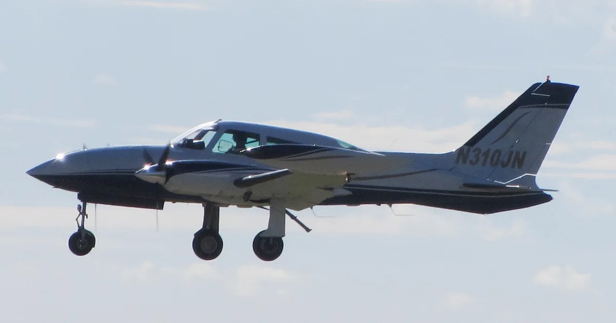
CESSNA 310Q · Maintenance Manual
Overview
This document serves as an Instructions for Continued Airworthiness (ICA) supplement for the Cessna 310 series aircraft, specifically addressing the Tailcone Stinger Assembly installation. It provides maintenance technicians with essential information to ensure the airworthiness of the tailcone stinger assembly, which is modified under FAA STC SA00873WI. The document outlines inspection requirements, maintenance schedules, and troubleshooting procedures specific to the tailcone stinger assembly. It is crucial for operators to integrate this information into their aircraft maintenance manuals and scheduled maintenance programs to comply with FAA regulations. The document emphasizes the importance of regular inspections and provides guidelines for the installation and maintenance of the tailcone stinger assembly, ensuring the aircraft remains in a safe and airworthy condition.
- Inspect the tailcone stinger assembly every 100 hours or annually.
- Check for cracks around the assembly and attachment screws during inspections.
- The tailcone stinger assembly weighs 5.5 lbs ± 0.5 lbs without paint.
- No airworthiness limitations are added by the installation of the tailcone stinger assembly.
- Troubleshooting should be performed by FAA-approved repair stations.
Document
Source
Originally published by avfab.com. Sprinkle hosts a reference copy with an added summary, specifications and searchable full text.
Document details
- Type
- Maintenance Manual
- Year
- 2014
- Pages
- 10
- File size
- 105 KB
- Publisher
- avfab.com
Common. One of the most common aircraft types we track.
Full essential library on file for the CESSNA 310Q.
CESSNA 310Q for sale now


Free — save the 310Q to your watchlist and track it in one place.
More CESSNA 310Qmanuals & documents
See all 23 →- SERVICE BULLETIN - Plane-Power | AlternatorsService Bulletins
- supplemental type certificate 10084369 - Rosen Sunvisor SystemsSupplemental Type Certificate
- Fuel starvation and forced landing involving Cessna 310R, VH-DAWOther Documents
- MEB-34-05 - SERVICE BULLETINMaintenance Manual
- LANDING GEAR - LANDING GEAR WARNING HORN REPLACEMENTParts Catalog
- Flight Test Guide for Certification of Transport Category AirplanesPilot's Operating Handbook
- United States National Search and Rescue SupplementTraining Manual
- Cessna Multi-Engine Service Bulletin MEB-27-02Service Bulletins
- CESSNA 310G - Inflight Pilot TrainingChecklist
- FAA Approved Installation Manual for the EDM-960 systemWiring Diagram
- Acceptable Methods, Techniques, and Practices – Aircraft AlterationsAdvisory Circular
- Installation Instructions for Cessna 310 . . 400 Series Aircraft Sunvisor System (Kit RC300/400-300-1)Systems Description
If you fly the CESSNA 310Q, you may also be researching these.



In this document
Inspection Requirements and Overhaul Schedule
The tailcone stinger assembly must be inspected every 100 hours or annually, as per 14 CFR 23.1529. The inspection includes checking for cracks around the assembly and attachment screws, as well as any damage to the body of the assembly. There are no additional overhaul time limitations specified.
Dimensions and Access
The installation of the tailcone stinger assembly does not alter the aircraft's dimensions or access to existing systems, ensuring that maintenance and inspections can be performed without additional complications.
Airworthiness Limitations
The Airworthiness Limitations section is FAA approved and specifies the maintenance required under Sec. 43.16 and 91.403 of the Federal Aviation Regulations. There are no additional airworthiness limitations imposed by the installation of the tailcone stinger assembly.
Troubleshooting
For troubleshooting beyond the information provided in this document, technicians should refer to the existing Aircraft Maintenance Manual. It is recommended that troubleshooting be conducted by FAA-approved repair stations or qualified individuals with the necessary equipment.
Safety notes
- Ensure compliance with FAA regulations regarding maintenance and inspections.
- Only qualified personnel should perform troubleshooting and repairs.
Full document text
Aviation Fabricators Document No: AF-504 805 North Fourth Street Revision: (A) Clinton MO 64735 Date: January 15, 2014 Page 1 of 10 INSTRUCTIONS FOR CONTINUED AIRWORTHINESS For Tailcone Stinger Assembly Document No.: AF-504 Revision “A” Revision Date: 01/15/14 Applicable to: Cessna 310P, T310P, 310Q, T310Q, 310R, T310R Aircraft Modified by FAA STC SA00873WI The information in the Instruction for Continued Airworthiness is FAA accepted material and complies with 14 CFR 23.1529, Instructions for Continued Airworthiness. It supersedes or adds to that provided in the Maintenance Manual for the Cessna 310 Series Aircraft, only where covered in the items contained herein. For limitations and procedures not contained in the Supplement, consult the Component Maintenance Manual, or other approved airplane data. Aviation Fabricators Document No: AF-504 805 North Fourth Street Revision: (A) Clinton MO 64735 Date: January 15, 2014 Page 2 of 10 REVISION PAGE Document Title: Instructions for Continued Airworthiness Prepared By: Todd Pogue Reviewed By: Brian C. Adamson Updates to the ICA will be made by Aviation Fabricators Inc. Updates will be listed in the log of revisions and the effective pages will be listed below. Distribution: Per the requirement of Appendix G of 14 CFR Part 23 paragraph G23.1 (c), the changes made to the ICA by the applicant will be distributed via mail by means of paper copy. Log of Revisions REV. NO. EFFECTED PAGE(S) DESCRIPTION DATE APPROVED BY IR All Initial Release 07/01/10 D. Shepard A All -Updated Section 10 Limitations to latest format, pg 10 -Added section 11.0 Troubleshooting, pg 10 01/15/14 JRL Aviation Fabricators Document No: AF-504 805 North Fourth Street Revision: (A) Clinton MO 64735 Date: January 15, 2014 Page 3 of 10 TABLE OF CONTENTS INSTRUCTIONS FOR CONTINUED AIRWORTHINESS __________________________________ 1 REVISION PAGE_______________________________________________________________ 2 TABLE OF CONTENTS __________________________________________________________ 3 1.0 INTRODUCTION ___________________________________________________________ 5 2.0 INSPECTION REQUIREMENTS AND OVERHAUL SCHEDULE __________________________ 7 3.0 DIMENSION AND ACCESS ____________________________________________________ 8 4.0 LIFTING AND SHORING ______________________________________________________ 8 5.0 LEVELING AND WEIGHING ___________________________________________________ 8 6.0 TOWING AND TAXIIING _____________________________________________________ 8 7.0 PARKING AND MOORING ___________________________________________________ 8 8.0 PLACARDS AND MARKINGS __________________________________________________ 8 9.0 SERVICE INFORMATION _____________________________________________________ 9 10.0 AIRWORTHINESS LIMITATIONS _____________________________________________ 10 11.0 TROUBLESHOOTING ______________________________________________________ 10 Aviation Fabricators Document No: AF-504 805 North Fourth Street Revision: (A) Clinton MO 64735 Date: January 15, 2014 Page 4 of 10 ABBREVIATIONS AND DEFINITIONS Abbreviations Definitions AML FAA Approved Model List (AML) Detailed Inspection (DET) An intensive examination of a specific item, installation or assembly to detect damage, failure or irregularity. Available lighting is normally supplemented with a direct source of good lighting at an intensity deemed appropriate. Inspection aids such as mirrors, magnifying lenses, etc. may be necessary. Surface cleaning and elaborate access procedures may be required. FAA Federal Aviation Administration FAA MIDO FAA Manufacturing Inspection District Office General Visual Inspection (GVI) A visual examination of an interior or exterior area, installation or assembly to detect obvious damage, failure or irregularity. This level of inspection is made from within touching distance unless otherwise specified. A mirror may be necessary to enhance visual access to all exposed surfaces in the inspection area. This level of inspection is made under normally available lighting conditions such as daylight, hangar lighting, flashlight or droplight and may require removal or opening of access panels or doors. Stands, ladders or platforms may be required to gain proximity to the area being checked. ICA Instructions for Continued Airworthiness Special Detailed Inspection (SDI) An intensive examination of a specific item, installation, or assembly to detect damage, failure or irregularity. The examination is likely to make extensive use of specialized Inspection Techniques and/or equipment. Intricate cleaning and substantial access or disassembly procedure may be required. STC Supplemental Type Certificate Aviation Fabricators Document No: AF-504 805 North Fourth Street Revision: (A) Clinton MO 64735 Date: January 15, 2014 Page 5 of 10 1.0 INTRODUCTION The purpose of this Maintenance Manual Supplement and Instructions for Continued Airworthiness (ICA) is to provide the maintenance technician with the information necessary to ensure the continued airworthiness of the Aviation Fabricators Tailcone Stinger Assembly installation, per installation number 42- 0225, when installed in accordance with Aviation Fabricators design data included on STC Drawing List AF-297 and per Supplement Type Certificate (STC) SA00873WI. Modifications to an aircraft obligates the operator to include the maintenance information provided by this document into the operators aircraft Maintenance Manual and operator’s aircraft scheduled maintenance program. This document defines supplementary maintenance operations and frequencies recommended by Aviation Fabricators Inc., to ensure the aircraft’s airworthiness. The information contained herein addresses the requirements specified in 14 CFR 23.1529, Instructions for Continues Airworthiness and supplements the basic Airplane Maintenance Manual only in those areas listed as pertains to the installation of the tailcone stinger assembly, as installed per the Aviation
Show full textShow less
Fabricator STC Drawing List AF-297. For limitations and procedures not contained in this supplement, consult the basic Airplane Maintenance Manual. DATA All information to support the continued airworthiness of this modification is contained in: STC SA00873WI. STC Drawing List: AF-297. Installation: STC Drawing List: AF-297: Drawing D-10205 Parts: Refer to p/n 42-0225 STC Drawing List AF-297. The tailcone stinger assembly is a two piece assembly made from woven carbon graphite and vinylester resin. It is attached to the aircraft using screws and the taillight assembly is attached in the same manner as the OEM assembly. Design Change Control All data and changes to the parts and assemblies will be tracked per STC Drawing List AF-297 Rev C or later approved revision. Applicable Aircraft Cessna 310P, T310P, 310Q, T310Q, 310R, T310R Aircraft Aviation Fabricators Document No: AF-504 805 North Fourth Street Revision: (A) Clinton MO 64735 Date: January 15, 2014 Page 6 of 10 Tailcone Stinger Assembly P/N 42-0225 Figure 1.0A Aviation Fabricators Document No: AF-504 805 North Fourth Street Revision: (A) Clinton MO 64735 Date: January 15, 2014 Page 7 of 10 2.0 INSPECTION REQUIREMENTS AND OVERHAUL SCHEDULE 1. To comply with14 CFR 23.1529, inspect the tailcone stinger assembly per the following table 2. Inspection Time Limit for the tailcone stinger assembly installations: 100 hour inspection or annually 3. Recommended Overhaul Periods No additional overhaul time limitations. Task Code Schedule Date Mech Insp AFI-100 a. Check cracks around assembly and attachment screws. AFI-101 b. Check cracks, breaks, or any other damage to the body of the tailcone assembly. Aviation Fabricators Document No: AF-504 805 North Fourth Street Revision: (A) Clinton MO 64735 Date: January 15, 2014 Page 8 of 10 3.0 DIMENSION AND ACCESS The installation of the tailcone stinger assembly does not change the dimensions of the aircraft or alter the access to any existing aircraft system. 4.0 LIFTING AND SHORING No change. 5.0 LEVELING AND WEIGHING Tailcone Stinger Assembly = 5.5 lbs +/- .5 lbs without paint. 6.0 TOWING AND TAXIIING No change. 7.0 PARKING AND MOORING No change. 8.0 PLACARDS AND MARKINGS No placards are required in conjunction with this modification. Aviation Fabricators Document No: AF-504 805 North Fourth Street Revision: (A) Clinton MO 64735 Date: January 15, 2014 Page 9 of 10 9.0 SERVICE INFORMATION Service Instructions: Cleaning: 1. Clean tailcone stinger assembly with mild detergent and water typical of the aircraft fuselage. Maintenance Instructions: If any damage is found during inspection to the tailcone stinger assembly, contact Aviation Fabricators for replacement or repair. Removal and Installation of the Tailcone Stinger Assembly: Removal: 1. Remove attaching screws and move stinger assembly aft slightly. 2. Disconnect all electrical wires to the navigation light, strobe, and/or reel antenna if installed. 3. Remove stinger assembly from aircraft. Installation: 4. Attach tail navigation light and reel antenna to upper half of new tailcone stinger assembly and attach all electrical wiring. 5. Place upper half assembly up to aircraft tailcone, hold in a level position, and secure upper half to the aircraft using screws. 6. Assemble lower half assembly to the upper half assembly and aircraft using screws. Aviation Fabricators Document No: AF-504 805 North Fourth Street Revision: (A) Clinton MO 64735 Date: January 15, 2014 Page 10 of 10 10.0 AIRWORTHINESS LIMITATIONS The Airworthiness Limitations section is FAA approved and specifies maintenance required under Sec. 43.16 and 91.403 of the Federal Aviation Regulations unless an alternative program has been FAA approved. There are no Airworthiness Limitations to the aircraft with the addition of the tailcone stinger assembly installed by this STC. 11.0 TROUBLESHOOTING Refer to the existing Aircraft Maintenance Manual for troubleshooting the Tailcone Stinger Assembly that is required beyond the information found on the installation drawing D-10205. For replacement parts or repair of damage parts: Contact Aviation Fabricators at (660) 885-8317. Troubleshooting this installation should only be accomplished by FAA approved repair stations with the appropriate ratings or appropriately rated operator/individuals, with required test equipment and service data.
What's in the CESSNA 310Q TCDS
A Type Certificate Data Sheet (TCDS) is the FAA's record of what an aircraft type was approved as. It is the source of truth for weights, seating, fuel and the rules the design was certified against. Expand any line to see what it means.
6,038 CESSNA 310Q parts for sale
See all →
Parts listed for sale by vetted eBay sellers — confirmed on eBay at checkout.