Installation Instructions for Cessna 310 . . 400 Series Aircraft Sunvisor System (Kit RC300/400-300-1)
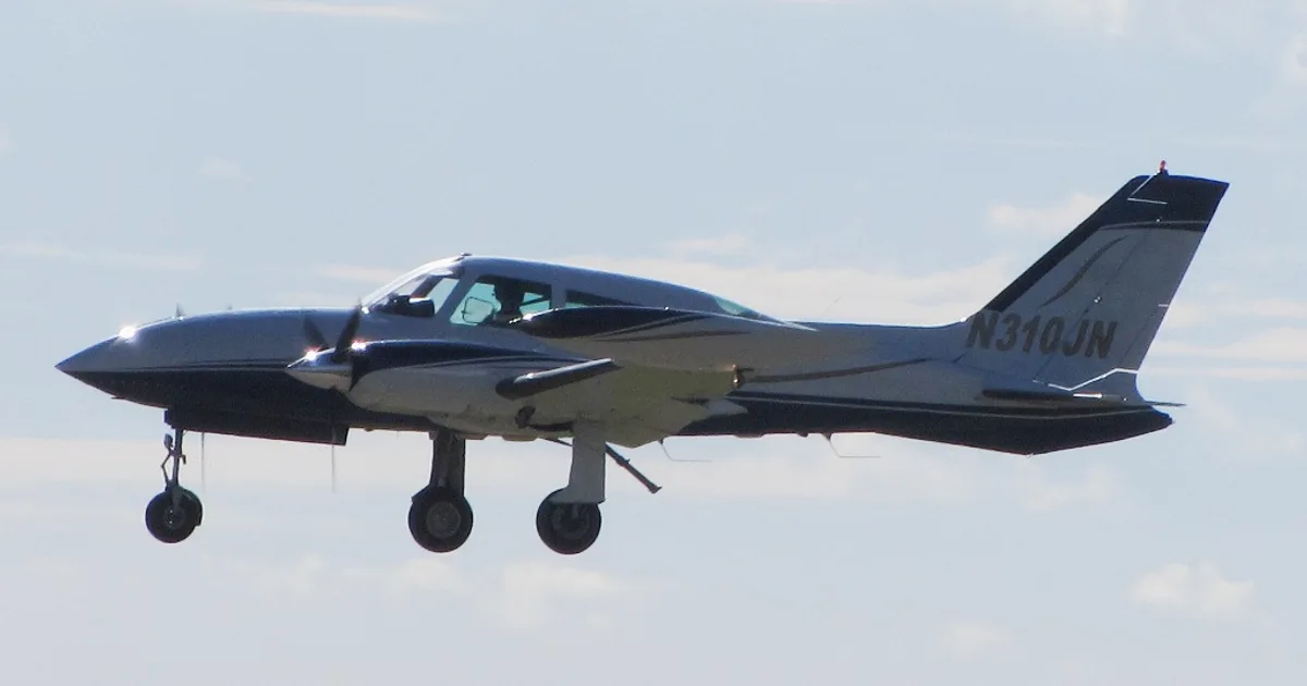
CESSNA 310Q · Systems Description
Overview
This document provides installation instructions for the Rosen Sunvisor System specifically designed for Cessna 310 and 400 series aircraft. It outlines the necessary tools, installation steps, and continued airworthiness instructions. The installation is straightforward and is expected to take approximately one hour. The document emphasizes the importance of following the instructions completely and includes notes on maintenance and care for the sunvisor system. It is essential for users to ensure that the installation complies with FAA regulations and to make a logbook entry upon completion.
- Installation takes approximately 1 hour.
- Requires a Phillips screwdriver and two Allen keys (5/32 and 9/64).
- Visors must stow overhead when in the forward position.
- Periodic cleaning and adjustment of the visor assemblies are recommended.
- No airworthiness limitations are associated with this installation.
Document
Source
Originally published by www.aircraftspruce.com. Sprinkle hosts a reference copy with an added summary, specifications and searchable full text.
Document details
- Type
- Systems Description
- Year
- 2007
- Pages
- 4
- File size
- 122 KB
- Publisher
- www.aircraftspruce.com
Common. One of the most common aircraft types we track.
Full essential library on file for the CESSNA 310Q.
CESSNA 310Q for sale now


Free — save the 310Q to your watchlist and track it in one place.
More CESSNA 310Qmanuals & documents
See all 23 →- SERVICE BULLETIN - Plane-Power | AlternatorsService Bulletins
- supplemental type certificate 10084369 - Rosen Sunvisor SystemsSupplemental Type Certificate
- Fuel starvation and forced landing involving Cessna 310R, VH-DAWOther Documents
- MEB-34-05 - SERVICE BULLETINMaintenance Manual
- LANDING GEAR - LANDING GEAR WARNING HORN REPLACEMENTParts Catalog
- Flight Test Guide for Certification of Transport Category AirplanesPilot's Operating Handbook
- United States National Search and Rescue SupplementTraining Manual
- Cessna Multi-Engine Service Bulletin MEB-27-02Service Bulletins
- CESSNA 310G - Inflight Pilot TrainingChecklist
- INSTRUCTIONS FOR CONTINUED AIRWORTHINESS Tailcone ...Maintenance Manual
- FAA Approved Installation Manual for the EDM-960 systemWiring Diagram
- Acceptable Methods, Techniques, and Practices – Aircraft AlterationsAdvisory Circular
If you fly the CESSNA 310Q, you may also be researching these.



In this document
Installation Steps
The installation process involves removing the existing stock ball mount visors using a Phillips screwdriver and attaching the new Rosen Sunvisors with the provided screws. Specific configurations for the swivel mount bracket are detailed based on the orientation of the mounting holes. The installation is completed by ensuring that the visors stow properly.
Tools Required
The installation requires a Phillips screwdriver, a 5/32 Allen key, and a 9/64 Allen key. These tools are not included in the installation kit.
Continued Airworthiness Instructions
Users are advised to periodically clean the visor lenses with a soft cloth and mild soap or an approved aviation-grade cleaner. Additionally, it is recommended to adjust the pivot tensions on the visor assemblies as needed.
Airworthiness Limitations
The document states that there are no specific airworthiness limitations associated with the installation of the sunvisor system, but it is essential to comply with FAA regulations regarding maintenance.
Full document text
86365 College View Road Eugene, Oregon USA 97405 541.747.0034 w w w . r o s e n v i s o r . c o m Page 1 of 2 Installation Instructions for Cessna 310 . . 400 Series Aircraft Sunvisor System (Kit RC300/400-300-1) (Kit RCS-300-6) R1180000-006 This is a FAA STC’d installation requiring a logbook entry upon completion. Doc: 9051-0118-015 Rev Date Approved C 11/5/2007 GH Installing your Rosen Sunvisor System is easily performed and should take approximately 1 hour. Please read these short instructions COMPLETELY before starting. Tools Required (not included): Phillips Screwdriver 5/32 Allen Key 9/64 Allen Key Installation Hardware (included): Qty: (4) #10-32 Flat Head Screw NOTE: On Cessna 310’s this system will only fit applications that have the original ball joint style equipment as shown. • Using a Philips screwdriver, remove (2) stock ball mount visors. • If your mounting holes are positioned fore and aft in relationship to the centerline of your aircraft, your swivel should look like this when viewed from behind: • If your mounting holes are positioned perpendicular to the centerline of your aircraft, your swivel should look like this when viewed from behind: • If necessary, reconfigure swivel mount bracket as indicated. • This image is the pilot’s side of a longitudinal configuration. • Attach your new Rosen Sunvisors using the #10- 32 Flat Head Screws provided. NOTE: The red Thumb Screw knob should be forward, away from the operator. • Repeat for the other side. • Installation is now complete. Use and Care Instructions: • Visors will stow in different positions, but generally the system will stow overhead when in the forward position. Continued Airworthiness Instructions: • (On the ground only) o Periodically clean the lenses with a soft cloth, mild soap and water or an approved aviation grade windscreen cleaner. Do not use abrasives on the lens. o Periodically adjust the pivot tensions on the visor assemblies. • Updates to this continued airworthiness section are available on the Rosen Website. (www.rosenvisor.com) The most up to date version of this document is available on the Rosen Website. (www.rosenvisor.com) Airworthiness Limitations: The Airworthiness Limitations Section is FAA approved and specifies maintenance required under §§43.16 and 91.403 of the Federal Aviation Regulations unless an alternative program has been FAA approved. There are no airworthiness limitations associated with this installation. 86365 College View Road Eugene, Oregon USA 97405 541.747.0034 w w w . r o s e n v i s o r . c o m Page 2 of 2 Installation Instructions for Cessna 414A, 421B Series Aircraft Sunvisor System (Kit R1181300-0) This is a FAA STC’d installation requiring a logbook entry upon completion. Doc: 9051-0118-022 Rev Date Approved C 11/6/2007 GH Installing your Rosen Sunvisor System is easily performed and should take approximately 1 hour. Please read these short instructions COMPLETELY before starting. Installation Hardware (included): Qty: (2) E-clip (1) #10-32 Cap Screw (1) #8-32 x 5/8 Cap Screw (1) 5/32 Allen Key (1) 9/64 Allen Key NOTE: This installation fits Cessna Models 414A and 421B aircraft with standard visor on swing mounts. • Remove the stock visors by loosening the socket head cap screws on the swing arms and then removing the E-clips from the top surface. Work the visor assembly down to remove. surface. wivel t head cap screw on the swing arm (see above illustration). • Install the Rosen swivel into the swing arm from the bottom up, with the E-clip groove towards the top, until the groove is accessible from above the swing arm, and install the provided E-clip on the top • Pull the swivel down until the E-clip rests on the top surface of the swing arm. Tighten the s clamp socke • Rotate the swing arm until the swivel post is as vertical as possible. (It may be necessary to loosen the swing arm pivot clamp using an Allen key through the trim access hole.) Tighten the swing arm pivot clamp. NOTE: The red slide tensioning screw should be towards the windscreen when properly installed. • Remove the protective paper coverings from both sides of the visor before use. • Installation is now complete. 86365 College View Road Eugene, Oregon USA 97405 541.747.0034 w w w . r o s e n v i s o r . c o m Page 1 of 2 Continued Airworthiness Instructions: • (On the ground only) o Periodically clean the lenses with a soft cloth, mild soap and water or an approved aviation grade windscreen cleaner. Do not use abrasives on the lens. o Periodically adjust the pivot tensions on the visor assemblies. • Updates to this continued airworthiness section are available on the Rosen Website. (www.rosenvisor.com) The most up to date version of this document is available on the Rosen Website. (www.rosenvisor.com) Airworthiness Limitations: The Airworthiness Limitations Section is FAA approved and specifies maintenance required under §§43.16 and 91.403 of the Federal Aviation Regulations unless an alternative program has been FAA approved. There are no airworthiness limitations associated with this installation. 86365 College View Road Eugene, Oregon USA 97405 541.747.0034 w w w . r o s e n v i s o r . c o m Page 2 of 2
What's in the CESSNA 310Q TCDS
A Type Certificate Data Sheet (TCDS) is the FAA's record of what an aircraft type was approved as. It is the source of truth for weights, seating, fuel and the rules the design was certified against. Expand any line to see what it means.
6,038 CESSNA 310Q parts for sale
See all →
Parts listed for sale by vetted eBay sellers — confirmed on eBay at checkout.