Fuel starvation and forced landing involving Cessna 310R, VH-DAW
CESSNA 310Q · Other Documents
Overview
This document is an investigation report by the Australian Transport Safety Bureau (ATSB) detailing an incident involving a Cessna 310R aircraft, registered as VH-DAW. The report outlines the events leading to a forced landing due to fuel starvation, the pilot's actions, and the subsequent findings regarding fuel management and operational oversight. It serves as a critical resource for understanding the factors contributing to the incident, including pilot training, fuel management practices, and the importance of accurate fuel gauge readings. The report emphasizes the need for thorough pre-flight planning and adherence to emergency procedures to enhance safety in aviation operations.
- The Cessna 310R experienced dual engine surging due to fuel starvation during a flight on June 20, 2023.
- The pilot failed to manage fuel selection properly, leading to inadequate fuel for both engines.
- Accurate fuel gauge readings are critical; the pilot relied on faulty gauges during pre-flight planning.
- Emergency procedures must include thorough checks of fuel levels and tank selections before flight.
- Pilot training should emphasize fuel management and emergency procedures to prevent similar incidents.
Document
Source
Originally published by www.atsb.gov.au. Sprinkle hosts a reference copy with an added summary, specifications and searchable full text.
Document details
- Type
- Other Documents
- Year
- 2023
- Pages
- 79
- File size
- 3.6 MB
- Publisher
- www.atsb.gov.au
Common. One of the most common aircraft types we track.
Full essential library on file for the CESSNA 310Q.
CESSNA 310Q for sale now


Free — save the 310Q to your watchlist and track it in one place.
More CESSNA 310Qmanuals & documents
See all 23 →- SERVICE BULLETIN - Plane-Power | AlternatorsService Bulletins
- supplemental type certificate 10084369 - Rosen Sunvisor SystemsSupplemental Type Certificate
- MEB-34-05 - SERVICE BULLETINMaintenance Manual
- LANDING GEAR - LANDING GEAR WARNING HORN REPLACEMENTParts Catalog
- Flight Test Guide for Certification of Transport Category AirplanesPilot's Operating Handbook
- United States National Search and Rescue SupplementTraining Manual
- Cessna Multi-Engine Service Bulletin MEB-27-02Service Bulletins
- CESSNA 310G - Inflight Pilot TrainingChecklist
- INSTRUCTIONS FOR CONTINUED AIRWORTHINESS Tailcone ...Maintenance Manual
- FAA Approved Installation Manual for the EDM-960 systemWiring Diagram
- Acceptable Methods, Techniques, and Practices – Aircraft AlterationsAdvisory Circular
- Installation Instructions for Cessna 310 . . 400 Series Aircraft Sunvisor System (Kit RC300/400-300-1)Systems Description
If you fly the CESSNA 310Q, you may also be researching these.

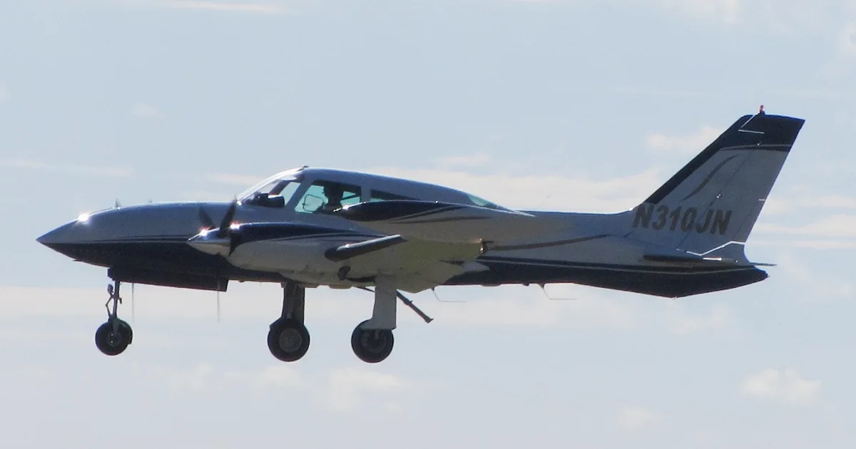


In this document
Investigation Summary
The investigation summary provides an overview of the incident involving the Cessna 310R, focusing on the fuel starvation that led to a forced landing. The pilot's decision-making process during the flight and the operational pressures faced by the pilot are highlighted.
Pilot Information
This section discusses the qualifications and experience of the pilot, including their flight hours and training on the Cessna 310R. It notes the pilot's lack of familiarity with the aircraft's fuel management system, which contributed to the incident.
Aircraft Information
Details about the Cessna 310R, including its specifications, fuel system, and operational capabilities. The report emphasizes the importance of understanding the aircraft's fuel management system to prevent similar incidents.
Emergency Procedures
The report outlines the emergency procedures that should be followed in the event of engine surging and fuel starvation. It stresses the importance of selecting the correct fuel tanks and maintaining awareness of fuel levels.
Safety Analysis
This section analyzes the factors that contributed to the incident, including pilot training deficiencies, fuel management errors, and operational pressures. Recommendations for improving safety practices in fuel management are provided.
Safety notes
- Pilots must ensure they are fully familiar with the aircraft's fuel system and capacity.
- Conduct thorough pre-flight inspections, including verification of fuel quantity.
- Ensure appropriate tank selections are made during flight to avoid fuel starvation.
Full document text
Fuel starvation and forced landing involving Cessna 310R, VH-DAW About 5 km south-east of Derby Airport, Western Australia on 20 June 2023 ATSB Transport Safety Report Aviation Occurrence Investigation (Systemic) AO-2023-029 Final – 30 April 2025 Released in accordance with section 25 of the Transport Safety Investigation Act 2003 Publishing information Published by: Australian Transport Safety Bureau Postal address: GPO Box 321, Canberra, ACT 2601 Office: 12 Moore Street, Canberra, ACT 2601 Telephone: 1800 020 616, from overseas +61 2 6257 2463 Accident and incident notification: 1800 011 034 (24 hours) Email: atsbinfo@atsb.gov.au Website: www.atsb.gov.au © Commonwealth of Australia 2025 Ownership of intellectual property rights in this publication Unless otherwise noted, copyright (and any other intellectual property rights, if any) in this publication is owned by the Commonwealth of Australia. Creative Commons licence With the exception of the Commonwealth Coat of Arms, ATSB logo, and photos and graphics in which a third party holds copyright, this report is licensed under a Creative Commons Attribution 4.0 International licence. The CC BY 4.0 licence enables you to distribute, remix, adapt, and build upon our material in any medium or format, so long as attribution is given to the Australian Transport Safety Bureau. Copyright in material used in this report that was obtained from other agencies, private individuals or organisations, belongs to those agencies, individuals or organisations. Where you wish to use their material, you will need to contact them directly. Addendum Page Change Date › iii ‹ Investigation summary What happened On 20 June 2023, a Cessna 310R, registered VH-DAW and operated by Broome Aviation, was being flown on an air transport operation with a pilot and one passenger from Broome Airport to Turkey Creek, Western Australia (WA) and return. On the return flight, the pilot planned to stop at Derby Airport, to refuel. On the return flight from Turkey Creek to Derby, the aircraft’s right engine began surging while being supplied from the auxiliary fuel tank. The pilot changed the tank selection to the right main tank, which had little fuel remaining. The right engine began surging a second time and the pilot determined there was enough fuel in the left main tank to sustain both engines to Derby. The pilot then selected the right engine to cross feed from the left main fuel tank. Ten minutes later, both engines began surging. The pilot, assessing they had a dual engine fuel starvation, began switching fuel tanks searching for any remaining fuel. Unable to stop the engine surging, the pilot extended the landing gear and banked into a right turn with the intention of landing on the Derby Highway. During the turn, the right wing of the aircraft contacted a tree causing the aircraft to turn 180° and come to an abrupt stop on the edge of the highway. The pilot sustained serious injuries, and the passenger sustained minor injuries. The aircraft was substantially damaged. What the ATSB found The occurrence The ATSB found that the planned flight from Broome to Turkey Creek and return to Derby with the required fixed reserve and contingency fuel could not be achieved without refuelling the aircraft en route. In addition, the pilot did not intend to use all the available fuel in the auxiliary tanks and did not take this into consideration in their pre-flight planning, further reducing the amount of fuel available. Also, the aircraft fuel gauges did not indicate accurately. The ATSB also found that the pilot inadvertently did not select the fuel supply to the right engine to the right auxiliary fuel tank during the first leg of the journey and did not manage the fuel in accordance with the pilot's operating handbook requirements. This resulted in the depletion of fuel in the main tanks to a level where continuous engine operation could not be maintained. Further, after the fuel in the right main fuel tank had been used, the pilot did not divert the aircraft to the closest airport, select the left engine to the left auxiliary fuel tank, or maintain altitude to increase their safety margin. Additionally, the pilot was not wearing an upper torso restraint during the forced landing resulting in the pilot receiving serious head injuries during the collision. The pilot also had a lack of understanding of the aircraft fuel planning, fuel management and emergency procedures, and due to a lack of consolidation training and limited to no operational oversight these issues were not detected. Operator oversight The ATSB also found that during the 8-month period from November 2022 until the accident, Broome Aviation provided its pilots transitioning to operating the Cessna 310 with limited supervision, guidance and support, including management of the fuel system. In addition, aircraft defects were not being written on the maintenance release, leading to several defects not being rectified or managed. Further, Broome Aviation pilots experienced pressure to not report aircraft defects on maintenance releases, and many pilots also experienced or observed pressure from company › iv ‹ management to conduct flights in aircraft with defects that they considered made the aircraft unsafe for flight. Finally, Broome Aviation’s operations manual did not include a procedure for recording in-flight fuel calculations. As a result, pilots adopted varying methods for fuel monitoring, leading to reduced assurance of accurate in-flight fuel management. Civil Aviation Safety Authority oversight The ATSB identified that, following a complaint by a former Broome Aviation pilot regarding management pressure on pilots to operate unserviceable aircraft, the Civil Aviation Safety Authority (CASA) conducted a level 2 surveillance activity on the operator in early June 2023 with a key scope element being to evaluate the complaint. In addition, CASA received further
Show full textShow less
complaints after the accident, that were also added to a level 1 surveillance activity in August 2023. However, the surveillance activity and the associated reports did not assess the subject of the complaints. Additionally, CASA approved a head of flying operations (HOFO) for Broome Aviation in early December 2022 via an abbreviated assessment as they had already been assessed for another operator and due to an expectation that it was an interim appointment. The person subsequently remained in the position for a much longer period and, when this situation was identified by CASA, the HOFO’s ability to continue undertaking the position when returning to work for another operator full time as a line pilot and alternate HOFO was not fully assessed. What has been done as a result Broome Aviation updated its operations manual to the new format exposition in response to Civil Aviation Safety Authority (CASA) findings during a level 1 surveillance audit. It now outlines an in-flight fuel management procedure. The operator now has both a full-time HOFO and an alternative HOFO, who is also the Safety Manager. The new HOFO reported that all company pilots are fully aware that they are available to address questions or concerns. The operator has also modified its check and training system, implementing a revised check and training procedure and updated documentation to facilitate the tracking of pilot training and competency in line with current Civil Aviation Safety Regulations (CASR). The new HOFO has changed the defect reporting process to ensure all defects are reported to either the HOFO or the alternative HOFO, and where required noted on the MR. The operator is now using maintenance releases to systematically document defects, ensuring that issues with aircraft in the fleet are properly tracked and addressed. Finally, Broome Aviation has implemented a safety management system in line with the current CASR in relation to a CASA audit finding. Monthly safety meetings are now being held to address safety concerns. Safety message Accidents involving fuel mismanagement are an ongoing aviation safety concern. In addition to the importance of ensuring there is sufficient fuel prior to, and during, flight, this occurrence reinforces the need to: • be fully familiar with the aircraft’s fuel system and capacity • conduct a thorough pre-flight inspection, including verification of the fuel quantity • ensure the appropriate tank selections are made • ensure all aircraft documentation and placarding is up to date and readily available. This accident and many other previous accidents demonstrate the importance of pilots having knowledge of the aircraft type and its systems, especially when faced with an abnormal situation. › v ‹ Operators, as part of their safety management processes, should provide the opportunity for skill consolidation during and following the initial training on a new aircraft type to reduce safety risk during this transition. This is particularly relevant for types with increased complexity compared to those a pilot has previously flown. Pilots have a vital role in ensuring maintenance personnel are aware of all aircraft defects to enable prompt rectification and compliance with aviation regulations. This includes documenting aircraft defects on the maintenance release (MR) accurately and without omission. Failing to record defects compromises aircraft airworthiness and safety, placing crew, passengers, and operations at unacceptable risk. Pilots who perceive serious risks, such as defects not being addressed, management pressure to operate defective aircraft, or being discouraged from documenting defects on the MR, are urged to report these concerns through their organisation’s safety management system (SMS). The SMS is designed to provide a structured and confidential channel for reporting safety issues to enable investigation and resolution. If internal reporting channels are ineffective or unavailable, pilots are encouraged to report safety concerns confidentially to either the Civil Aviation Safety Authority’s confidential reporting system (Reporting illegal behaviour | Civil Aviation Safety Authority) or the ATSB’s REPCON scheme (REPCON – Aviation Confidential Reporting Scheme | ATSB). These reporting systems ensure the identity of individuals is protected, while enabling critical safety issues to be addressed. Accurate reporting of safety concerns and occurrences is essential to preventing accidents and fostering a strong safety culture. › vi ‹ Contents Investigation summary ..........................................................................................................iii The occurrence iii Operator oversight iii Civil Aviation Safety Authority oversight iv The occurrence ........................................................................................................................1 Overview 1 Broome to Turkey Creek 1 Turkey Creek to Derby 1 Context ......................................................................................................................................4 Pilot information 4 Qualifications and experience 4 Recent history 5 Medical information 6 Aircraft information 6 Fuel System 6 Vortex generators 9 Site and wreckage 9 Accident site 9 ATSB examination 11 Aircraft maintenance 12 Maintenance release 12 Defect reporting process 14 Reported aircraft issues 14 Aircraft placarding 20 Fuel management 23 Pre-flight fuel plan 23 Previous flight 25 Fuel quantity analysis of the accident flight 25 Operator fuel planning requirements 27 Regulatory requirements 28 Operator requirements for training, experience and consolidation on new aircraft types 29 Induction and minimum qualifications 29 Supervisory pilots 30 Emergency procedures 32 Engine surging 33 Survivability 34 Safety briefing 34 Seatbelts and upper torso restraints 35 Emergency locator transmitter 35 Operator and management information 36 Overview 36 Chief executive officer 36 Head of flying operations 37 Oversight of operations 38 Safety management system 40 Organisational pressures 40 Civil Aviation Safety Authority oversight 41 Head of flying operations assessment 41 Complaints to CASA 44 Surveillance activities 46 Related occurrences 48 › vii ‹ Safety analysis ...................................................................................................................... 49 Introduction 49 Management of fuel 49 Pre-flight planning 49 Pilot perception of fuel available in the auxiliary tank 50 Broome to Turkey Creek 50 Return flight leg 50 Continued operation with defective fuel gauges 51 Operator’s procedures for fuel management 52 Response to the emergency 53 Factors influencing pilot performance 54 Pilot experience and consolidation on the Cessna 310 54 Operator continued oversight and guidance 54 Defect reporting 55 Legibility and accuracy of aircraft internal placards 56 Survival aspects 56 Upper torso restraints 56 Emergency locator transmitter 57 Operational pressures 57 Regulatory oversight 58 CASA response to complaints 58 Head of flying operations assessment 59 Findings ................................................................................................................................. 61 Contributing factors 61 Other factors that increased risk 62 Safety issues and actions ................................................................................................... 63 General details ...................................................................................................................... 68 Glossary ................................................................................................................................. 69 Sources and submissions .................................................................................................. 70 Australian Transport Safety Bureau .................................................................................. 72 About the ATSB 72 ATSB – AO-2023-029 › 1 ‹ The occurrence Overview On 20 June 2023, a Cessna 310R, registered VH-DAW and operated by Broome Aviation, was being prepared for an instrument flight rules (IFR)1 air transport operation with a pilot and one passenger from Broome Airport, Western Australia (WA) to Turkey Creek, WA. On the return flight, the pilot planned to stop at Derby Airport to refuel before returning to Broome Airport (Figure 1). Figure 1: VH-DAW flight plan Source: Google Earth, annotated by the ATSB Broome to Turkey Creek At Broome Airport, the pilot completed flight planning, using software provided by the operator. They then completed the pre-flight checks of the aircraft, including visually confirming all 4 fuel tanks (see the section titled Fuel system) were full. The pilot then delivered a safety briefing to the passenger, which included the use of seatbelts, the location of the emergency locator transmitter (ELT) and the first aid kit. The aircraft departed Broome at 0542 local time. The pilot supplied fuel to both engines from the main fuel tanks for 60 minutes before selecting the auxiliary fuel tanks. They advised that after 30 minutes, they reselected the main tanks and continued to Turkey Creek. The pilot indicated that when switching between fuel tanks, they recorded the duration of usage for each tank and calculated the anticipated fuel consumption on a printed flight plan as the operator did not have a formal inflight fuel log. The aircraft landed at Turkey Creek at 0744. The pilot shut down the engines and left both fuel selectors on the main tanks position. The pilot did not check the total remaining fuel on the gauges at that time. Both the pilot and the passenger left the runway strip for approximately 6 hours. The pilot recalled being able to see the aircraft from the building in which they were waiting for the passenger to complete their business. Turkey Creek to Derby Upon returning to the aircraft, the pilot completed a fuel quantity check by dipping the main tanks with a dipstick. They recalled that the left main tank had 110 L of fuel, which was in line with what they expected (see the section titled Pre-flight fuel plan). However, the right main tank contained 1 Instrument flight rules (IFR) are a set of regulations that permit the pilot to operate an aircraft in instrument meteorological conditions (IMC), which have much lower weather minimums than visual flight rules (VFR). ATSB – AO-2023-029 › 2 ‹ only approximately 70 L of fuel. The pilot turned on the aircraft battery to compare the dipstick readings to the fuel gauge readings and reported that both main tank fuel gauge indications correlated with the dipstick readings. Upon checking the auxiliary tank gauges, the pilot noted the right auxiliary tank gauge was indicating full, 40 L more fuel than expected, and the left was indicating as expected. Due to the design of the auxiliary fuel tanks, the amount of fuel contained in the tank can only be visually verified when the tank is full. The pilot stated they did not visually confirm the fuel level in the auxiliary tanks at that time as they assumed both auxiliary tanks had been used during the flight to Turkey Creek. The pilot assumed the difference in fuel distribution between the tanks may have been due to an internal fuel leak from the right main tank to the right auxiliary tank, while they were on the ground at Turkey Creek, which they reported had occurred on a previous occasion (see the section titled Main to auxiliary tank fuel leak). However, the pilot was confident there was enough fuel on board, between all 4 fuel tanks, to fly the second leg of the flight to Derby Airport based off an expected 1.5 hour flight time. The pilot used these revised fuel quantity figures for pre-flight fuel planning and filled in the relevant sections of the journey log. At 1333, the pilot started the engines, taxied out to the runway and at about 1339 departed Turkey Creek with the main tanks selected. At about 1439, the pilot switched from main fuel tanks to the auxiliary tanks. Approximately 10 minutes later, the pilot changed the fuel tank selection for the left engine to run off the left main tank. The pilot kept the right engine selected to the right auxiliary tank due to the extra 40 L of fuel they had detected during the pre-flight fuel check. Due to belief that they could only draw fuel for 45 minutes from the auxiliary fuel tanks (see the section titled Limited fuel draw from auxiliary tanks), the pilot calculated there was approximately 30 minutes of fuel available for use in the right auxiliary tank. At about 1454, (15 minutes after they had selected the right auxiliary fuel tank), the right engine began surging. Unsure why they were unable to run the right engine on the right auxiliary tank for longer, the pilot reselected the right main fuel tank, which resolved the surging. The pilot advised that, as the autopilot had difficulty maintaining altitude (see the section titled Autopilot), they selected it to OFF when the engine issues began. Ten minutes later, the right engine began to surge again. The pilot switched back to the right auxiliary fuel tank, however the surging continued. Now at the top of descent for Derby, the pilot deliberated 2 options: shut down the right engine and fly asymmetrically or crossfeed the right engine to the left main tank and run both engines off the left main tank. After checking the fuel gauges, the pilot determined there was enough fuel in the left main tank (approximately 45 L) to run both engines to Derby. The pilot then selected the right engine to crossfeed from the left main fuel tank and referred to the quick reference handbook for engine failure in flight checklist to determine a possible cause for the surging. ATSB – AO-2023-029 › 3 ‹ Figure 2: VH-DAW flight path 1. Change from main tanks to auxiliary tanks; 2. Change the left engine from auxiliary tank to main tank; 3. Right engine surge – changed the right engine to right main tank; 4. Right engine surge – crossfeed right engine off left main tank; 5. Inbound call for Derby Airport; 6. Dual engine surge; 7. Mayday call; 8. Accident site. Source: Google Earth, annotated by the ATSB At 1511, the pilot made an inbound call for Derby Airport on the common traffic advisory frequency. Both engines began surging 3 minutes later. The pilot, assessing they had dual engine fuel starvation, selected the fuel pumps to HIGH and began switching fuel tank selections, searching for any remaining fuel. They advised that after they selected each tank, they waited for a response however, there was no improvement. The pilot advised that the engines did not stop but they could not maintain altitude. At 1516:40 the passenger began video recording the flight due to its ‘apparent turbulence’, capturing the engines surging. The recording concluded about 30 seconds later, as the pilot initiated a MAYDAY2 call to Brisbane Centre air traffic control, stating ‘dual engine failure, suspected engine fuel starvation and I have to put it down on the road’. Brisbane Centre acknowledged the MAYDAY, requested the pilot activate their ELT on landing, and requested details on the number of people on board. The pilot did not respond. The pilot alerted the passenger to the emergency and told them to brace for impact. Approximately 30 seconds later, the pilot extended the landing gear and banked into a right turn with the intention of landing on the Derby Highway. However, during the turn the right wing of the aircraft hit a tree causing the aircraft to turn 180⁰ and come to an abrupt stop on the edge of the highway. Upon landing, the pilot was temporarily rendered unconscious. The passenger called emergency services and a local passerby stopped to help the pilot and passenger. The passenger recalled the area smelling of fuel when stepping out of the aircraft. The pilot sustained serious facial injuries and the passenger sustained minor injuries. The aircraft was substantially damaged. 2 MAYDAY: an internationally recognised radio call announcing a distress condition where an aircraft or its occupants are being threatened by serious and/or imminent danger and the flight crew require immediate assistance. ATSB – AO-2023-029 › 4 ‹ Context Pilot information Qualifications and experience The pilot held a commercial pilot licence (aeroplane), issued in December 2020. They also held a multi-engine aircraft (MEA) class rating (issued on 21 June 2021), and an MEA command instrument rating (issued/renewed on 27 August 2021). At the time of the accident, the pilot had about 776 hours of total flying experience, with about 613 hours as pilot in command and 43.4 hours as pilot in command of MEA. The pilot joined the operator in July 2022, commencing operations on the Cessna 210 (C210). After a period of induction and flying in command under supervision (ICUS), the pilot completed a proficiency check with the substantive3 head of flying operations (HOFO) (see the section titled Head of flying operations) on the C210 and then commenced passenger air transport operations as pilot in command. Prior to joining the operator, the pilot had accumulated a total of 37.6 hours on MEA, of which 35 hours were dual day flying and 2.6 hours were dual night flying, completed during the pilot’s initial MEA flight training in 2019. Up until that time, the pilot’s MEA experience had all been gained on the Piper Seminole (PA-44). In November 2022, the pilot and other pilots from the operator hired an external instructor, at their own expense, to complete instrument proficiency checks (IPCs) on MEA, using VH-DAW. CASA did not require pilots to have a type-specific endorsement for the Cessna 310 (C310). By the end of November 2022, the pilot had completed online theory training relating to the basic operation of the C310 and IFR theory, including a Civil Aviation Safety Authority (CASA) MEA questionnaire. On this assessment, the pilot had incorrectly stated the size of the C310 auxiliary tanks (see the section titled Fuel system), and the requirement to use the main tanks for 60 minutes prior to using the auxiliary tanks (see the section titled Fuel management). In mid-December 2022, when the external instructor visited the organisation for the flight component of the IPC, the instructor assessed the MEA questionnaire using the aircraft’s pilot’s operating handbook (POH). They later advised that they noted the errors, and while they did not correct the answer on the questionnaire, they discussed the correct answers with the pilot. The pilot’s C310 IPC training included general handling skills, stalls, turns, circuit operations, instrument approaches, asymmetric training, and an outline of how the auxiliary tanks were used. The auxiliary tanks were used for no more than 10 minutes during the first flight. The pilot obtained their IPC on 16 December 2022. The instructor noted that, although fuel management was not explicitly covered during the IPC flights, they had an expectation it would be covered during the organisation’s line training. In total, the pilot gained approximately 8.1 hours ICUS on the C310 by the end of December 2022 (Table 1). The pilot then returned to flying the C210 for the operator. A check-to-line flight on the C310 was planned to be conducted during a passenger-carrying air transport operation on 21 March 2023, however this flight was cancelled due to a hydraulic malfunction with the aircraft. A shorter, non-air transport operation, check-to-line flight was 3 The substantive HOFO held the position with the operator prior to December 2022 and after June 2023. ATSB – AO-2023-029 › 5 ‹ subsequently conducted by the interim4 HOFO on 25 March 2023, 130 days after their IPC was issued. The pilot had not flown the C310 in the interim. The check-to-line flight with the interim HOFO covered various operational aspects, however it was focused on ensuring the pilot was proficient flying under the IFR. The pilot could not recall completing emergency procedures during this flight or using the auxiliary fuel tanks. The pilot was assessed as competent in all areas. At the end of the check-to-line flight, the pilot had accrued 10.5 hours ICUS on the C310. Table 1: Pilot ICUS hours After completing the check-to-line flight, the pilot alternated between operating the C210 and the C310, accumulating 37 hours on the C210 and 43.4 hours on the C310 prior to the accident. At the time of the accident, the pilot had 53.9 hours experience on the C310, including 43.4 hours in the 90 days prior to the accident. Recent history In the 7 days prior to the day of the accident, the pilot completed flights on 14 June (4.6 hours flight time), 15 June (1.9 hours flight time), and 17 June 2023 (5.1 hours flight time). The pilot was rostered off duty on 18 and 19 June. They were within the operator’s flight and duty limitations for maximum cumulative flight and duty times in the 7 days prior to the accident (20 June). The pilot reported that, on the evening of 19 June, they retired to bed at 2030, woke up at 0300 and began their pre-flight duties at 0500. The pilot noted that they went to bed earlier than normal, due to the early start time, but could not fall asleep straight away. It is likely they obtained about 5–6 hours of sleep. The operator’s operations manual5 detailed that, when starting between 0500–0559, pilots had a maximum available flight duty period (FDP) of 9 hours. Due to the pilot being on the ground at Turkey Creek for 6 hours, the operator reported they had organised a suitable sleeping accommodation for the pilot to allow for a split shift. This arrangement allowed the pilot’s FDP to be extended by 4 hours. The pilot was unaware of this facility, stating the operator had never previously given them suitable sleeping accommodation during a long day shift, only when needing to stay overnight. The pilot reported they waited for the client in an air-conditioned room and had an adequate amount of food. The pilot reported that they felt somewhat rested during the day of the accident flight and recalled that, although they had gone to bed early, they had not fallen asleep straight away. Based on the available information, the ATSB concluded that the early wake-up time and long duty day were 4 The interim HOFO held the position from December 2022 to June 2023. 5 Broome Aviation was in a transitional state to the Civil Aviation Safety regulations Parts 119 and 135 requirements and still used a document known as an operations manual rather than the exposition required by the new regulations. Date Location Flight type Flight time 12/12/2022 Halls Creek Broome ICUS (air transport operation) 2.0 13/12/2022 Broome Broome ICUS (IPC) 1.8 14/12/2022 Broome Broome ICUS (IPC) 1.9 15/12/2022 Broome Broome ICUS (IPC) 1.2 16/12/2022 Broome Broome ICUS (IPC) 1.2 25/04/2023 Broome Derby Broome ICUS Check-to-line 2.4 ATSB – AO-2023-029 › 6 ‹ problematic but, overall, there was insufficient evidence to conclude that the pilot was experiencing a level of fatigue known to affect performance. Medical information The pilot held a class 1 aviation medical certificate that was current to 3 May 2024. This specified a requirement for the pilot to wear distance vision correction. The pilot stated that they did not have any medical concerns or issues in the period prior to the accident. Aircraft information The Cessna 310R is a twin-engine, low-wing, 6-seat, unpressurised aircraft equipped with retractable landing gear and powered by 2 Continental IO-520 piston engines. VH-DAW was manufactured in the United States and first registered in Australia in 1975. Broome Aviation became the registration holder on 12 July 2011. Fuel system The C310 fuel system consists of 2 sets of fuel tanks in the wings – main and auxiliary, that supply fuel to each engine independently. Two fuel selectors, one for each engine, are installed on the floor between the pilot seats. These allow selection of main fuel, auxiliary fuel, crossfeed and fuel shutoff (Figure 10). The selector allows fuel to flow from the selected fuel tank to the engine-driven fuel pump for the selected engine. Figure 3 shows the layout of the standard fuel system installed in the aircraft. ATSB – AO-2023-029 › 7 ‹ Figure 3: VH-DAW Fuel System 1. VH-DAW was fitted with both optional auxiliary tanks, totalling 31.5 US gallons on each side; 2. The aircraft did not have the optional low level fuel light fitted. Source: C310 POH, annotated by the ATSB ATSB – AO-2023-029 › 8 ‹ Main tanks The 2 main fuel tanks for the C310 are integrally-sealed aluminium tanks located on each wing tip. Each main tank holds 189 L (50 United States (US) gallons) of usable fuel, with approximately 7.5 L of unusable fuel. There are 2 fuel pumps in each main tank, the first (auxiliary fuel pump) is used to provide fuel pressure to prime the engine for start or to provide fuel pressure during an engine-driven fuel pump failure. The second (transfer pump), operates continuously during flight and allows the transfer of fuel from the nose section to the centre section of the main tank, where the fuel outlet is positioned. The transfer pumps are on the same electrical circuit as the left landing light. The main tanks are vented to atmosphere and if overfilled, fuel will be vented overboard through these vents. Auxiliary tanks The auxiliary fuel tanks are bladder-type tanks and are located in the outboard section of each wing. Each auxiliary tank holds 119 L (31.5 US gallons) of usable fuel. The POH stated that fuel could be drawn from the auxiliary tanks during cruise flight only. Engine-driven fuel pump Each engine had an engine-driven fuel pump that contained a bypass, which continuously returned excess fuel and vapour to their respective main tank. Fuel management The POH stated: If auxiliary fuel tanks are to be used, select main fuel for 60 minutes of flight (with 40-gallon auxiliary tanks) or 90 minutes of flight (with 63-gallon auxiliary tanks). This is necessary to provide space in the main tanks for vapor and fuel returned from the engine-driven fuel pumps when operating on auxiliary fuel. If sufficient space is not available in the main tanks for this diverted fuel, the tanks can overflow through the overboard fuel vents. It also stated: Since part of the fuel from the auxiliary tanks is diverted back to the main tanks instead of being consumed by the engines, the auxiliary tanks will run dry sooner than anticipated; however, the main tanks endurance will be increased by the returned fuel. The total usable fuel supply is available during cruise flight only. An engine failure or engine driven fuel pump failure results in the auxiliary fuel on the side of the failure to be unusable. It was recommended that auxiliary fuel was used until either exhausted or the flight phase had reached the top of descent. When questioned by the ATSB, neither the engine nor aircraft manufacturer could provide a fuel flow rate to calculate how much fuel was being returned to the main tank when the auxiliary tank was selected. The POH also advised ‘operation of the auxiliary fuel tanks near the ground (below 1,000 ft) is not recommended’. The pilot advised that to simplify fuel management, they routinely used the main tanks for 60 minutes on each segment of a flight before selecting auxiliary tanks. They did not mention the reasoning behind using 60 minutes rather than the expected 90 minutes associated with the larger auxiliary fuel tanks (as fitted to VH-DAW) detailed in the POH. Other pilots within the organisation who flew the C310 also reported using the 60-minute timeframe. Fuel flow gauge The fuel flow gauge indicated the approximate fuel consumption of each engine in pounds per hour. The POH stated that the gauge dial is ‘marked with arc segments corresponding to proper fuel flow for various power settings and is used as a guide to quickly set the mixtures. The gauge has markings for take-off and climb, and cruise power settings for various altitudes.’ ATSB – AO-2023-029 › 9 ‹ The pilot advised that they used the fuel flow gauge while leaning the engines to determine the engines were receiving the appropriate fuel flow and to ensure the flow was stable after changing fuel tanks. The pilot reported that this process was completed during the accident flight on all tank changes. Fuel quantity gauge One fuel quantity gauge was located above the right-side control column and indicated the weight of the fuel (in both US gallons and pounds) for the left and right fuel tanks on the display. The gauge showed the fuel quantity for the selected tanks (either main or auxiliary) and the fuel quantity in the non-selected tanks could be displayed through the use of a toggle switch below the gauge. There were also 2 yellow indicator lights (one for each side), these illuminated when the auxiliary tank on the selected side was selected (see Figure 7). The aircraft was not equipped with the optional independent low fuel warning lights for the main fuel tanks. Vortex generators VH-DAW was fitted with 88 vortex generators located on the wings and vertical fin with additional strakes mounted on the outboard of each engine nacelle. The Supplemental Type Certificate (STC) for this modification included various amendments to the limitations and performance, including reduced stall and VMCA6 speeds, and allowed for an increased operating weight. Site and wreckage Accident site The ATSB did not attend the accident site. The site was attended by members of the Western Australia (WA) Police Force on 20 June 2023 and by the aircraft operator the following day. The site inspection was recorded by the police and the video footage was provided to the ATSB, along with photographs taken on the day of the accident (Figure 4). 6 VMCA: the minimum speed, while in the air, that directional control can be maintained with one engine inoperative. ATSB – AO-2023-029 › 10 ‹ Figure 4: Accident site Source: Western Australia Police Force The wreckage was located on the edge of the road in an area of low foliage, approximately 2.8 NM (5.2 km) east-south-east of Derby Airport. The left main tank and right auxiliary tank were ruptured during the accident sequence. The left auxiliary tank was reported by the operator as being intact and found to contain about 20 L of fuel, while the right main tank contained negligible amounts of fuel. As both wings displayed visible damage (Figure 5), the ATSB was unable to verify if fuel had leaked from the fuel tanks following the ground collision. The propellers on both engines were not in the feathered position. ATSB – AO-2023-029 › 11 ‹ Figure 5: Left and right wing damage Top image – left wing; bottom image – right wing. Source: Western Australia Police Force, annotated by the ATSB While reviewing the video footage taken by the police onsite, the left landing light circuit breaker was found to have tripped. The ATSB could not verify if this occurred due to ground impact forces or during the flight. The operator arranged for the wreckage to be transported to a non-secure storage area at Broome Airport, which required the wings and one horizontal stabiliser to be separated from the fuselage. ATSB examination On 30 June 2023, the ATSB examined the wreckage focusing on the aircraft fuel system, particularly the right wing, both auxiliary fuel tanks, and the fuel quantity indicating system (FQIS). Despite the disruption during the accident sequence and transportation, no pre-existing defects or fuel system anomalies were identified. The following key components were retained for further examination and testing: • right and left auxiliary interconnect check valves • right and left vapour return check valves ATSB – AO-2023-029 › 12 ‹ • right fuel selector mains inlet port • right fuel selector auxiliary inlet port • FQIS indicator and signal conditioner. Detailed technical examination of these components identified the following defects in 3 components, which likely existed prior to the accident: • right fuel selector – main tank inlet valve did not seal when closed (i.e. when not selected ON) • the check valve in the right auxiliary tank outlet bleed return line (interconnecting the inboard and outboard fuel cells) did not seal in the reverse flow direction • the right vapour return line (engine driven fuel pump to main tank) check valve did not seal in the reverse flow direction. Testing of the check valve in the right auxiliary tank vent outlet bleed return line in the reverse direction identified a small leak. However, the testing indicated that the leak rate was significantly less than that required to allow fuel to have transferred from the main tank to the auxiliary tank while the aircraft was on the ground at Turkey Creek in the quantities reported by the pilot. Civil Aviation Safety Authority (CASA) Airworthiness Bulletin (AWB) 28-010 stated that if this valve was leaking, it could allow the engine-driven fuel pump to draw air into the fuel system resulting in either engine surging or loss of power. It was reported that this is most likely to occur when the auxiliary tank quantity was less than about half full. The differential pressure applied to the check valve during testing was likely far lower than expected operating pressures. Therefore, it is possible that during engine operation with the auxiliary fuel tank selected, as the fuel quantity reduced, the increased system pressure affected the leak rate and resulted in an increased reverse flow. This may allow the engine driven fuel pump to draw air in sufficient quantity to effect engine performance. There was no evidence of defects in the auxiliary tank inlet valve of the right fuel selector or the corresponding check valves from the left fuel system. The left fuel selector was not implicated in the occurrence and was therefore not tested. The FQIS indicator and signal conditioner were not tested or examined due to difficulty finding a facility capable of testing the signal conditioner. Although testing may have established the serviceability status of these individual components, aircraft accident damage prevented operational testing of the whole system. As such, evidence provided by pilots that the FQIS system was not indicating correctly was relied upon (see section titled Fuel gauge displays). Aircraft maintenance Maintenance release A maintenance release (MR) is required to be carried on an aircraft as an ongoing record of the aircraft’s time-in-service and airworthiness status. The operator’s system of maintenance stated that the MR was valid for 200 hours in service or 12 months from issue, with inspections to be completed at 50, 100, 150 and 200 flight hours. A daily inspection was required to be carried out and the MR signed to show the inspection had been completed, prior to the first flight of the day. The inspection and certification could be made by any pilot licenced to fly the aircraft, or an appropriately licenced aircraft maintenance engineer. After the last flight of the day and before the aircraft was next flown, the total daily flight time was required to be entered and the progressive total time in service recorded. ATSB – AO-2023-029 › 13 ‹ The MR is also used to record any maintenance which is due on the aircraft prior to the next periodic inspection, or any defects7 detected. The last periodic maintenance inspection was carried out on 11 May 2023 at 150 flight hours. At that time the aircraft total time in service was 18,630 hours. The aircraft had flown 30 hours since this inspection with no defects recorded. The only maintenance issue recorded on the MR was a hydraulic leak in the right main brake, which was rectified and signed off by a maintenance engineer on 24 April 2023. The ATSB interviewed all 5 pilots who had flown the operator’s C310 during the period from December 2022 to June 2023, as well as other pilots who flew the operator’s C210s. Most of the pilots interviewed stated they were encouraged not to write any defects with aircraft on the MRs. These pilots recounted that if any defects were documented on a MR, they would be reprimanded by the CEO and face a reduction in flight hours on the subsequent roster. The pilots also reported that the interim HOFO (see the section titled Head of flying operations) exhibited more willingness for defects to be documented on the MR, however they firstly required assurance that the reported matter was a legitimate defect. The pilots had mixed views on the stance of the substantive HOFO, with 3 noting they had been told not to write defects on the MRs. Two pilots stated they had attempted to implement a ‘snag’ recording system as an alternate method of recording defects, however this was never adopted. Most pilots advised that, to circumvent what they assessed as a restriction on using the MRs to record defects, they utilised a group chat to communicate specific issues they had encountered on different aircraft in the fleet. They also noted they found it easier to directly communicate with engineers in the maintenance facility if they had any issues after they completed a flight. This approach usually resulted in minor defects getting fixed immediately. The substantive HOFO stated they were unaware of any ongoing defects with the operator’s C310 and were unaware of any instances of the CEO reprimanding pilots due to the recording of defects on the MRs. They also stated that, on occasion, pilots deviated from the standard documented procedure for defect reporting (see the following section titled Defect reporting process). The interim HOFO also noted that any defects with aircraft in the fleet should have been reported to them and put on the MR, although even if this was not the case then pilots could go straight to the engineers in the maintenance facility to get the matters rectified. In relation to the C310, the HOFO stated the aircraft fuel gauges ‘weren’t fabulous’, however they did not offer an explanation why this was not written up on the MR. They reported being unaware of any other aircraft defects. The chief engineer advised that all defects would be reported to them by either the HOFO or the CEO using the operator’s defect reporting process. Contrary to the process advised by the pilots, the chief engineer advised that as Broome Air Maintenance was not a part of Broome Aviation, all rectification work had to be requested, and that pilots were not permitted to bypass the request. The CEO stated that if there was a defect with an aircraft, they would have expected the pilots to follow the company’s policy regarding defects and write them on the MR. When asked about the C310, the CEO recalled having no knowledge of any defects with the aircraft other than the autopilot not holding altitude. No reason was provided as to why this was not written on the MR. The CEO reported that the fleet were maintained to a high standard and that if a pilot found a defect on an aircraft it would be delt with accordingly. They dismissed the reports they would reprimand pilots for reporting defects, noting they were ‘pedantic’ about maintenance. 7 An imperfection that impairs the structure, composition, or function of an object or system of an aircraft or component. ATSB – AO-2023-029 › 14 ‹ Defect reporting process The operator’s operations manual outlined a formal process to report deficiencies detected between periodic inspections, which stated: Line pilots shall report any deficiencies to the [head of flying operations] HOFO, [head of maintenance control] HAMC and CEO via email; verbal or text message notification may be used as a secondary notification method where appropriate or required. Once an email was received from a pilot, the process required the HOFO to liaise with the HAMC to determine the steps to investigate and rectify the deficiency. The substantive HOFO advised that if a pilot were to call with an issue, if required, the HOFO would tell the pilot to endorse the issue on the MR and then the HOFO would follow up with engineering personnel. The chief engineer reported that they did not use the maintenance release to record defects. Rather, if defects were identified either by the operator or by the maintenance organisation, these defects would be rectified and recorded in the aircraft’s Broome Air Maintenance (BAM) worksheets. The ATSB inspected the aircraft logbooks and was unable to identify any unscheduled maintenance. The last unscheduled maintenance recorded in the logbooks was dated 2017. The interviewed pilots stated that if they detected an aircraft defect, it was easier to talk directly to individual engineers in the maintenance facility, as they were usually in the hangar when returning from a flight and it was more likely to be dealt with. Reported aircraft issues The operator’s pilots reported multiple issues with the aircraft to the ATSB, including: • inaccurate fuel gauge displays • an internal fuel leak from the right main tank to the right auxiliary tank • limited fuel draw from the auxiliary tanks • engine surging • inability of the autopilot to accurately maintain an assigned altitude • significant tail flutter. During an interview with the ATSB, the chief engineer reported that, to their knowledge, the aircraft was fully serviceable with no issues identified. They also advised they were not aware of the issues raised by the pilots. Fuel gauge displays Fuel calibration cards are aircraft specific and used to enable an accurate assessment of fuel quantity. The aircraft’s dual indicating fuel quantity gauge was last tested and calibrated on 24 June 2020. Pilots reported that the main tank calibration card was disregarded as it was considered inaccurate. There was no fuel calibration card relating to the auxiliary tanks. The ATSB was unable to confirm if the auxiliary tank calibration had occurred as there was no record in the maintenance worksheets or the aircraft logbook of the results. There was no regulatory requirement to record the results of a fuel gauge calibration test. The next due date to test and recalibrate the fuel gauges was expected to be in June 2024 in compliance with the CASA Civil Aviation Order (CAO) 100.5 General requirements in respect of maintenance of Australian Aircraft – 2011 and the operator’s system of maintenance. Pilots who operated the aircraft reported that the fuel gauges displayed significant inaccuracies when the tanks were full. Specifically, when the main tanks were full, the right main tank display ATSB – AO-2023-029 › 15 ‹ would exceed full scale deflection, while the left main tank display would under-read by approximately 64 L (105 lbs) (Figure 6). Figure 6: VH-DAW main tank fuel gauges Left image – expected fuel gauge indications for main tanks when full; right image – the reported fuel gauge indications for main tanks when full. Source: Braden Blennerhassett (Air Manager), edited by the ATSB It was reported that, as fuel was used during the fight, the displays became progressively more accurate, however there was still a large discrepancy between the displays (Figure 7). The expectation was that, when the fuel tank selection was changed from main to auxiliary or vice versa, both sides would be changed at the same time. ATSB – AO-2023-029 › 16 ‹ Figure 7: VH-DAW main tank fuel gauge indications after supplying the engines for the same time Both the left and right main tanks had been used for the same amount of time during the flight. Source: Pilot of VH-DAW, annotated by the ATSB It was reported that when the gauge was selected to the auxiliary tank display, there was also a discrepancy when the tanks were full, although the difference was not as significant as that observed with the main tank display. It was reported that the display for the left auxiliary tank under-read by approximately 9 L (15 lb), while the display for the right auxiliary tank under-read by approximately 36 L (60 lb) (Figure 8). Pilots did not indicate that the accuracy of the auxiliary tank gauge displays improved during use. However, it was noted that the auxiliary tanks were never used below about 12 L. ATSB – AO-2023-029 › 17 ‹ Figure 8: VH-DAW auxiliary tank fuel gauges Left image – expected fuel gauge display for auxiliary tanks when full; right image – reported fuel gauge display for auxiliary tanks when full. Source: Braden Blennerhassett (Air Manager), edited by the ATSB The fuel gauge inaccuracy was reported to be widely known by pilots and informally reported to individual engineers in the maintenance facility, however the defect was not recorded on the aircraft’s MR. Pilots reported that maintenance personnel informed them that the external organisation capable of fixing the gauges indicated that new sensors were needed, and that the process of fixing the gauge was lengthy and the necessary parts were costly and so it was unlikely it would be completed. The CEO stated they were unaware of any issues with the fuel gauges. The pilots advised that they adopted a time-based approach to track the amount of fuel in each tank during flight, noting there was no other guidance from the interim HOFO or senior management on how to manage the fuel quantity. Pilots stated that the most accurate way to ensure the known quantity of fuel on board prior to take-off was to depart Broome with full main and auxiliary tanks and, where possible, fill the main tanks to full when flying intermediate sectors. The aircraft minimum equipment list (MEL) allowed 1 display on the gauge to be inoperative8 providing a reliable means was established to ensure that the fuel quantity on board met the requirements for the intended flight. Main to auxiliary tank fuel leak The pilot of the accident flight and the supervisor of their first ICUS flight reported there were occasional instances where, having been fully refuelled, the right main tank would be missing approximately 10–30 L of fuel the following day. They further advised that when this occurred, the right auxiliary tank would overflow when the fuel cap was removed (Figure 9). This led the pilots to suspect a fuel leak between the right main and auxiliary tanks. 8 Inoperative: an item for a flight of an aircraft is inoperative if, due to a defect, the item, or a function of the item, does not accomplish its intended purpose, or consistently function within the operating limits or tolerances mentioned in the approved design for the item or the flight manual for the aircraft. ATSB – AO-2023-029 › 18 ‹ Figure 9: Auxiliary fuel tank overflowing on morning inspection Source: Previous operator pilot, annotated by the ATSB This issue was informally reported to maintenance staff, but not recorded on the MR. The CEO reported being unaware of the issue. After the initial report, the reporting pilot noted that engineers in the maintenance facility were unable to identify a fuel leak. Although the issue reportedly recurred, it was not further reported. Limited fuel draw from auxiliary tanks The pilot of the accident flight stated that the auxiliary fuel tanks could only supply the engines for 40–45 minutes before surging occurred. They noted that their initial understanding of the limited fuel draw came from the supervisor of their first ICUS flight. They further advised observing this limitation on their first solo passenger-carrying flight in the aircraft. This issue was informally reported to individual engineers in the maintenance facility by the supervising pilot, and they recalled that maintenance was unable to identify a cause. The pilot of the accident flight assumed that since the issue had been reported previously, it had been addressed by maintenance. However, both the CEO and the chief engineer advised being unaware of the issue. Other pilots stated that around the 40-minute mark while using auxiliary tanks, the aircraft’s engines would lightly surge before regaining power. They would then continue to use the fuel from the auxiliary tanks until about 12 L remained, before changing to the main tanks. The HOFO reported there were no issues when using the auxiliary tanks. ATSB – AO-2023-029 › 19 ‹ Engine surging Multiple pilots recalled that the engines would surge during flight. The pilot of the accident flight and one other pilot noted the surging generally occurred when operating on auxiliary tanks, which they attributed to the limited fuel draw issue. Other pilots also recalled the engines surging however, they could not confirm which tanks were selected at the time. These surges were described as minor and intermittent, typically ceasing after a few seconds and did not require the fuel pumps to be selected ON. The engine surging had been reported to individual engineers in the maintenance facility verbally and had not been documented on the MR. Both the CEO and the chief engineer advised that they were unaware of this issue. Autopilot altitude hold According to pilots who operated VH-DAW, the aircraft’s autopilot maintained an accurate heading, however, despite pre-flight testing of the system reportedly consistently indicating that the autopilot was fully operational, it could not maintain an assigned altitude. There was no evidence or record that this issue was formally or informally reported to the engineers in the maintenance facility, and the chief engineer advised not being aware of the issue. However, the issue was known to the organisation’s CEO, at the time of the occurrence. An autopilot was considered inoperative if it was unable to maintain both altitude and heading. The aircraft MEL allowed continued operation with the autopilot inoperative under any one of the following conditions: • if flight was operated under IFR rules for RPT, charter9 or aerial work, the aircraft was equipped with dual controls and had 2 control seats, with one control seat occupied by the pilot in command of the aeroplane and the other seat occupied by a person holding a commercial pilot (aeroplane) licence with an endorsement on the aircraft and an instrument rating • if the flight was operated under IFR rules with a single pilot for RPT, charter or aerial work, the flight was within the period of 3 days commencing on the day on which the autopilot became inoperative provided only one capability of the autopilot system was unserviceable • the flight was operated under VFR rules • the flight was operated for a private flight. Elevator flutter Pilots reported the presence of a known elevator flutter10 on the aircraft, which was attributed to the installation of vortex generators on the elevator. This flutter resulted in challenging handling characteristics at low speeds, particularly during take-off and landing. The engineers in the maintenance facility had conducted an extensive investigation into the issue in 2018, including the removal and reinstallation of the vortex generators. They concluded that the flutter did not impose stress on the airframe, and the aircraft was returned to service on 13 August 2018. The vibration defect was raised again on the MR on 20 October 2022 and cleared by maintenance personnel on 4 November 2022. There was no information regarding what was completed during the November sign-off. The pilot of the accident flight stated that the elevator flutter was still present, although not noted on the accident flight. 9 Under previous legislation, air transport operations were split into regular public transport (RPT) and charter flights. 10 Elevator flutter: refers to an uncontrolled, rapid oscillation or vibration of the elevator control surface. This phenomenon can occur due to aerodynamic forces, structural dynamics, or a combination of factors. ATSB – AO-2023-029 › 20 ‹ Aircraft placarding The fuel selectors had plaques stating the amount of fuel in each tank in US gallons. On inspection, it was noted that the auxiliary tank capacity for both sides incorrectly indicated that small auxiliary tanks (20 US gallons) were fitted to the aircraft (Figure 10). Figure 10: VH-DAW fuel selector plaques Source: Operator, annotated by the ATSB This contradicted the usable fuel decals next to each filler cap on the airframe, which identified that the auxiliary tanks held 119 litres (31.5 US gallons) (Figure 11). Figure 11: VH-DAW fuel decals Source: ATSB ATSB – AO-2023-029 › 21 ‹ Just above the fuel selector plaques, there was a requirement for a plaque specifying how long to operate on the main tanks when first taking off with full tanks. For a C310 with the larger auxiliary tanks, the plaque was required to include: Use main tanks for takeoff, landing and first 90 minutes of flight. This plaque was missing from the aircraft (Figure 12). ATSB – AO-2023-029 › 22 ‹ Figure 12: VH-DAW internal placards relating to the fuel system Top image – VH-DAW internal fuel placarding; bottom image – exemplar internal fuel placarding. Source: Top image – ATSB; bottom image – Textron, annotated by the ATSB All aircraft placarding was required to be checked under the aircraft system of maintenance every 200 hours for security, presence and legibility. There was no requirement to check the validity of the information presented on the placards. The aircraft had five 200-hourly maintenance events in the last 5 years, the last being August 2022. ATSB – AO-2023-029 › 23 ‹ The fuel selector placards had last been replaced on 24 October 2008, prior to the aircraft being registered to Broome Aviation. The installed placards were the incorrect part number and as such displayed the incorrect size of the auxiliary tanks. The ATSB was unable to determine if the plaque relating to the 90 minutes on mains had been removed previously or never installed. The pilot of the accident flight was unaware that any of the plaques were incorrect, noting that they had not discussed it with the instrument proficiency check (IPC) instructor (see the section titled Qualifications and experience) or HOFO. Fuel management Pre-flight fuel plan The flight plan used by the pilot on the day of the occurrence was destroyed during the accident and was not recorded by the operator’s planning software. During the draft report review process the pilot advised that they had recently found a copy of the flight plan, which they provided to the ATSB. The plan (Figure 13), generated by the flight planning software, showed a zero fuel margin. The pilot stated that they did not input the expected winds for the flight as they were unaware how to. Additionally, they recalled that all their previous flight planning had been conducted with nil wind. Figure 13: Accident flight fuel plan Source: The accident pilot ATSB – AO-2023-029 › 24 ‹ A pre-flight fuel plan was created using the operator’s software (Figure 14). The flight plan software used a 120 L/h fuel burn for cruise and 150 L/h for climb. These figures were extracted from the POH performance tables using the typical operating conditions encountered for different phases of flight when flying out of Broome Airport.11 The known winds on the day of the occurrence were used. The fuel plan showed that the aircraft could not legally fly with the required reserves on the return flight to Derby. Figure 14: Example fuel plan based off reported winds for each sector of the occurrence flight Trip T – Trip total less taxi fuel; Contin – Contingency fuel (15% of expected trip total); F. Reserve – Fixed reserve; Fuel R – Fuel required for next leg including contingency and fixed reserve; Margin – Endurance subtracting fuel required; Endce – Endurance. Source: Operator, annotated by the ATSB The ATSB also generated a fuel plan based on the pilot’s understanding of the amount of fuel they could use from the auxiliary tanks. The analysis used: • the flight times calculated by the operator’s software • the pilot’s standard use of 40 minutes from the auxiliary tanks • 1.5 x fuel burn rate12 – the extra fuel was diverted to the main tanks. This resulted in approximately 120 L of fuel being available for use from the auxiliary tanks (40 L plus the redraw of 20 L = 60 L from each auxiliary tank). Therefore, the pilot’s perceived total available fuel onboard when all tanks were full was 498 L (main tanks 378 L + auxiliary tanks 120 L). As shown in Table 2, such a plan indicated there was insufficient fuel onboard to conduct the flight without fuel starvation. Table 2: Fuel calculation comparison 11 The Cessna 310R POH detailed numerous fuel flow rates for specific power settings. 12 This was a conservative rate of fuel burn as the engine manufacturer could not give an expected fuel return rate as this was dependent of the engine power used and the conditions on the day. ATSB calculated Leg 1 ATSB calculated Leg 2 Start fuel 498 L 241L Trip fuel (climb + cruise + taxi) 257 L 251 L Expected remaining fuel onboard at destination 241 L -10 L Contingency fuel 37 L 36 L Fixed fuel reserve 90 L 90 L Fuel margin 114 L -136 L ATSB – AO-2023-029 › 25 ‹ A previous pilot of the C310 indicated that when flying the same route, on the return leg they would refuel the aircraft at Halls Creek, another base for the operator, as it was 77 NM south-west of Turkey Creek. They would then fly directly from Halls Creek to Broome. This flight route ensured they had enough fuel to complete the flight with reserves intact. Previous flight The pilot recalled completing the same flight 4 weeks prior to the occurrence. They stated that they had landed at Derby and refuelled the aircraft for the final leg back to Broome. A retrospective fuel log was created using the known winds on that day and the pilot’s reported timing of the fuel tank changes (Table 3). The ATSB also calculated the average fuel burn for the aircraft during this flight using the fuel added to refuel the aircraft to full after the flight which showed the aircraft used an average of 124 L/h. The operator’s standard 12 L taxi fuel was used for the first leg of the flight. Due to the prevailing wind, the first leg from Broome to Turkey Creek was recorded as having a duration of 126 minutes, requiring the pilot to use the auxiliary tanks for 40 minutes (66 L draw from auxiliary tanks and 22 L returned to the main tanks on both sides). The flight time from Turkey Creek to Derby was recorded as 90 minutes. Due to the assumed auxiliary tank issue and having used the auxiliary tanks for 40 minutes on the first leg, the pilot would have likely used main tanks for the entire leg. It is highly probable that the pilot landed at Derby with 21 L of useable fuel remaining in each of the main tanks, equating to about 15 minutes of remaining engine operation before fuel exhaustion. Table 3: Retrospective fuel log of previous flight Broome – Turkey Creek – Derby on 25 May 2024 Fuel quantity analysis of the accident flight The ATSB obtained flight data that was transmitted at regular intervals from a V2 Flight Tracker, which had been installed on the aircraft. A retrospective fuel log for the Turkey Creek to Derby leg (Table 4) was created using: • the pilot’s recalled amount of fuel in each tank on startup • the pilot’s recollection of when they completed tank changes • the operator’s average fuel consumption rate of 120 L/h FUEL LOG Broome – Turkey Creek Phase Left Right Auxiliary Main Main Auxiliary Taxi Broome 119 189 189 119 Departure Broome 119 183 183 119 Change to auxiliary tanks 119 123 123 119 Change to main tanks 59 143 143 59 Estimated fuel on landing 59 117 117 59 Turkey Creek – Derby Taxi Turkey Creek 59 117 117 59 Departure Turkey Creek 59 111 111 59 Estimated fuel on landing 59 21 21 59 ATSB – AO-2023-029 › 26 ‹ • a conservative estimate of fuel return (0.5 multiplier) to the main tanks when using auxiliary tanks • a conservative estimate of fuel draw from the left main tank (2.5 multiplier) and return to the right main tank (0.5 multiplier) when cross feeding the right engine. As such, it is only indicative of the fuel on board in each tank at each change of tank and at the time of the dual engine surging. Table 4: Retrospective fuel log of remaining fuel in aircraft from Turkey Creek to the point of the dual engine surge using 120 L/h At the point of dual engine surge, it is estimated that the left main tank had approximately 9 L of fuel remaining. The aircraft manufacturer stated that if the engines were surging while on the main tanks and there were no other issues with the fuel system and fuel available in the auxiliary tanks, the pilot should have been able to use the remaining fuel in the auxiliary tanks to regain full power. At the point of the dual engine surge, the left auxiliary tank had approximately 59 L and the right had approximately 97 L available. The same calculations were completed using the pilot’s average fuel consumption rate of 124 L/h (see the section titled Operator fuel flow check). Those calculations (Table 5) indicated that about 6 L of fuel remained in the left main fuel tank (supplying both engines) at the point of the dual engine surging. Table 5: Retrospective fuel log of remaining fuel in aircraft from Turkey Creek to dual engine surge using the pilot’s average 124 L/h FUEL LOG Turkey Creek – Dual engine surge Phase Left Right Auxiliary Main Main Auxiliary 1336: Taxi Turkey Creek (used 6 L each side) 74 110 70 119 1339: Departure Turkey Creek 74 107 67 119 1439: Change to auxiliary tanks 74 44 4 119 1449: Change left auxiliary to main tank 59 49 (44+5) 9 (4+5) 104 1454: Change right auxiliary to main tank 59 44 12 (9+3) 97 1504: Cross feed left main tank 59 34 2 97 1514: Dual engine surging 59 9 7 (2+5) 97 FUEL LOG Turkey Creek – Dual engine surge Phase Left Right Auxiliary Main Main Auxiliary 1336: Taxi Turkey Creek (used 6 L each side) 73 110 70 119 1339: Departure Turkey Creek 73 104 64 119 1439: Change to auxiliary tanks 73 42 2 119 1449: Change left auxiliary to main tank 58 48 (42+6) 8 (2+6) 104 1454: Change right auxiliary to main tank 58 42 10 (8+2) 96 1504: Crossfeed left main tank 58 32 1 96 1514: Dual engine surging 58 6 5 (1+4) 96 ATSB – AO-2023-029 › 27 ‹ Operator fuel planning requirements Pre-flight The operator’s procedures required the pilot to complete pre-flight fuel planning using the available electronic flight planning software. However, if the flight planning software was not available, the pilots were required to calculate the fuel required for the flight using the fuel flow guidelines for the aircraft. The operations manual outlined the fuel figures, specific to the C310, to be used when manually completing fuel planning. The guidelines did not contain a fuel flow rate for climb. However, they did include a block (total) fuel margin of 47 L which was to be available for each sector. The operator advised they were not aware of where the margin of 47 L figure had originated from. The electronic flight planning software did not include this 47 L margin fuel when calculating fuel requirements. To confirm the amount of fuel on board prior to flight, the operator’s fuel policy required pilots to visually confirm the fuel quantity in each tank using a dip or drip stick when possible, then compare this to the flight plan and fuel gauges. If there was a discrepancy more than an allowable margin with the fuel gauges the pilots were required to inform the HAMC and/or HOFO to determine the possible cause. The allowable margin quantity was not listed in the operator’s fuel policy. Inflight The operator’s procedures required pilots to recalculate fuel in flight at 2 specific points: • when reaching cruise • if required to divert. The procedures outlined that once reaching cruise altitude pilots should: calculate the remaining quantity of fuel on board for the proposed destination. This must be equal to or above the legal minimum final reserve quantity. If this is not the case, consider using more conservative fuel power settings, change cruise level for more favourable winds or divert to an alternative. The procedure did not stipulate if this calculation was required to be recorded on any documentation, nor did it outline any requirement for a fuel crosscheck. Additionally, the operator did not have a fuel log or method of monitoring fuel during the flight. If the pilot was required to divert, inflight fuel replanning was to be carried out using the fuel flow guidelines for the aircraft. A previous pilot for the operator stated there was no standardised method of completing inflight fuel logs and it was based on pilot preference. They further reported a ‘feeling’ that the organisation had not had any fuel starvation events due to ‘luck’. Post-flight The operator’s procedures recommended that pilots conduct a fuel gauge check against the value on the fuel totaliser at the completion of a flight. However, the operator stated that none of its aircraft were fitted with a fuel totaliser. Additionally, the quantity of fuel used was to be checked against the expected burn from the flight plan. Pilots were required to complete the fuel documentation, including recording on the journey log and manifest the amount of fuel at shutdown. The manifest did not provide the option to indicate the remaining fuel in each tank. ATSB – AO-2023-029 › 28 ‹ Operator fuel flow check The operator reported that pilots were required to enter the amount of fuel consumed and flight time after each flight into the organisation’s data recording software. The program created a monthly report, which outlined the fuel flow rate for each flight, segregated by aircraft. The substantive HOFO used this information to determine the average fuel flow for each aircraft, and which pilot completed each flight. If there was an unexpected trend for a particular pilot, the substantive HOFO would use this to discuss how the pilot was configuring the aircraft’s fuel system during flight. If the trend was over multiple pilots, the HOFO would liaise with maintenance to determine the cause. The substantive HOFO noted there was no indication that the aircraft was burning more than the expected 120 L/h however, they could not confirm if this process was being completed by the interim HOFO while they were on leave. ATSB analysis of the pilot’s flight times and fuel uplift over the previous 10 flights indicated the aircraft was using 124 L/h on average. Regulatory requirements Pre-flight fuel planning According to Civil Aviation Safety Regulation (CASR) Part 135 Australian air transport operations – smaller aeroplanes section 135.205 operators are required to provide pilots with an exposition which provides comprehensive tools, procedures, and guidance for effective pre-flight fuel planning. The exposition must outline step-by-step instructions for calculating fuel requirements to ensure compliance with Australian regulations and operational safety. According to CASR Part 135.D.6 and the Manual of standards (MOS) Part 135 7.04, pilots must have access to resources for determining fuel needs for each phase of the flight, including: • taxi fuel • trip fuel • holding fuel • destination alternate fuel • contingency fuel • final reserve fuel There should also be a process outlining: • fuel calculations • determining and recording fuel quantities – pre-flight • recording fuel quantities. To support these calculations, operators must provide tools such as flight planning software, fuel calculation tables, or automated planning systems. Operators are also responsible for ensuring that pilots are trained to use these resources effectively and can adjust their fuel requirements based on dynamic operational factors, such as deteriorating weather or delays. Part 135 manual of standards (MOS) Section 7.03 (2) required that the pilot in command must consider the effect of the relevant meteorological reports and forecasts when determining the quantity of useable fuel. ATSB – AO-2023-029 › 29 ‹ In-flight fuel management The Part 135 MOS Section 7.05 (2) required that the exposition outline a process for regular inflight fuel checks, which required the pilot to: • determine the amount of fuel remaining • analyse planned fuel consumption against actual consumption • determine there is sufficient fuel on board • calculate the amount of fuel expected to remain at the destination. According to the CASA Advisory circular 1-02 V4.1 Exposition and operations manual fuel policy guidance Annex D, the exposition should detail what maximum discrepancy between the actual fuel on board (gauge / visual) and calculated (journey log) figure is tolerable, noting that industry practice is a maximum of 3% discrepancy. Part 135 MOS section 7.03 required that operators must provide pilots with aircraft-specific fuel consumption. This could be sourced from the aircraft/engine manufacturer or taken from recent historical consumption records. Operators should also require pilots to document any significant deviations in fuel consumption or incidents involving fuel advisories or emergencies. This data enables operators to analyse and improve fuel planning and management procedures. In addition, Part 135 MOS section 7.06 required that operators must also ensure that the exposition outlines clear procedures for pilots to follow in the event of a low-fuel situation, including: • a minimum fuel state • emergency fuel situation. Finally, operators should regularly review and update their operational manuals to reflect lessons learned from safety reports and audits, ensuring continuous improvement in fuel management practices. Operator requirements for training, experience and consolidation on new aircraft types Induction and minimum qualifications The operator’s operations manual stated that recruited pilots were to meet the following minimum requirements: • commercial pilot licence with no medical restrictions13 • current Australian medical certificate • pass of a pre-employment check flight with the HOFO or a delegate. Once inducted, a new pilot would learn the routes with existing pilots before being checked to line by the HOFO. The operator’s operations manual stipulated 5 minimum requirements for a pilot in command of the C310 (Table 6). Table 6: Operator’s 5 minimum requirements for operating the C310 13 Medical restriction, as defined by the operator, was any condition that required the carriage of an additional flight crewmember. Requirement number Minimum requirements 1 5 hours on type for VFR operation 2 10 hours on type for IFR operation ATSB – AO-2023-029 › 30 ‹ The HOFO was required to conduct a check-to-line flight and, if successful, the pilot would be cleared to conduct air transport operations as pilot in command on the new type. The substantive HOFO stated that generally it would be expected that multiple ICUS flights would occur with either the HOFO or a supervisory pilot before a check-to-line would be conducted. The CEO reported that generally 15–20 hours on type would be sufficient to conduct line operations as pilot in command. During the draft review process, the CEO reported that the calibre of pilots coming through from flight schools was lower than previously experienced, noting that a lot of the organisation’s time was spent getting pilots up to commercial standard. After completing the check-to-line flight, the pilot of the accident flight had accrued a total flying time of 740.5 hours. The operator received an exemption from the operator’s insurer for the pilot to undertake air transport operations in the C310 without meeting the specified minimum requirement of 750 hours. Under CASR 61.650, pilots were required to have completed an IPC in the previous 12 months to fly a multi-engine aircraft under the IFR. The IPC must also be done in a multi-engine aircraft of the same category. The substantive HOFO noted that, once a pilot was checked to line, there was no follow up or specific oversight on their operating capabilities until their next proficiency check in 12 months, in line with the CASR requirements and the operations manual, which stated: If flying under the IFR, pilots are required to conduct an Instrument Proficiency Check with an authorised Flight Examiner prior to one (1) year from the last day of the month in which it was issued (IFR operations). There were no specific regulatory requirements for Broome Aviation to provide additional consolidation flights for pilots transitioning to the C310 as, at the time of the accident, the operator was operating under CASA exemption 87/21.14 In December 2021, Civil Aviation Safety Regulation (CASR) Part 135 (Australian air transport operations – smaller aeroplanes) commenced. It introduced more stringent requirements for flight crew training and checking for operators conducting air transport operations. However, operators could operate under the exemption that applied to a significant proportion of the previous small charter sector. This meant the operator was not required to conduct line training, a check-to-line, or complete proficiency checks, other than to ensure those proficiency checks and flight reviews mandated by Part 61 of CASR were carried out on their flight crew members. Supervisory pilots The CASA-AMC/GM Part 119 - Australian air transport operators - certification and management v 2.3 noted that some operators have diverse fleets and there are scenarios where the HOFO may not be qualified on every aircraft type or in every role/function performed under its air operator’s certificate (AOC). In this case, operators can elect to use a structure where another pilot is identified to complete that position. In the case of Broome Aviation, the substantive HOFO 14 CASA EX87/21 was an exemption instrument providing certain operators with deferrals from specific requirements of the Flight Operation Regulations particularly concerning safety management systems, human factors principles & non-technical skills, and training & checking. The deferrals applied to certain operators only and were subject to conditions. Requirement number Minimum requirements 3 Minimum of 750 total flying hours 4 Minimum 20 hours in command on MEA for VFR operation 5 A multi engine command instrument rating if flying IFR. ATSB – AO-2023-029 › 31 ‹ conducted the check and training for the C210, in addition to nominated supervisory pilots, but for the MEA this position was covered by supervisory pilots. The operator required that supervisory pilots had: • a minimum of 20 hours total time on type • completed training with the HOFO or nominated person (with such training including the use of the line training and check forms) • met the relevant recency or proficiency requirements to act as pilot in command • been nominated, in writing, by the operator to be supervisory pilot and recorded as a named supervisory pilot. The operator’s supervisory pilot register had not been updated since 1 December 2021. The register contained the name of one pilot who had been approved to conduct supervisory flights for the C310, however this pilot left the operator while the substantive HOFO was on leave. A second pilot had been listed as a supervisory pilot for the C210. The substantive HOFO stated that the second pilot had been assessed to conduct supervisory flights for the C310, however the register had not been updated to include this information. This pilot (detailed below as ‘Pilot 1’) also left the operator while the substantive HOFO was on leave. During the period between December 2022 and June 2023, 7 pilots flew the operator’s C310, including one who had completed the training but had not been checked to line. Multiple pilots stated that training and guidance on the C310 during this period was limited. Of the 7 pilots: • Pilot 1 – was a senior pilot for the operator who was signed off as a supervisory pilot for the C310. They conducted the check-to-line for Pilot 2. Pilot 1 left the operator at the end of December 2022 and returned for 3 weeks at the end of February 2023. • Pilot 2 – completed no ICUS flights prior to completing a check-to-line flight in November 2022 that lasted 1.1 hours. The pilot was not formally signed off as a supervisory pilot on the C310, although they had extensive instructional time on MEA, prior to assisting with ICUS flights. The pilot left the operator at the end of February 2023. • Pilot 3 – completed 2 ICUS flights, one with the interim HOFO (3.7 hours) and 1 with Pilot 2 (1.6 hours), before completing a check-to-line (1.5 hours) with the interim HOFO a week later in February 2023. The pilot left the operator at the end of March 2023. • Pilot 4 (pilot of the accident flight) – completed 1 ICUS flight with Pilot 2 and 4 IPC flights with the external instructor on the aircraft. They were subsequently checked to line in April 2023, 130 days after their last flight in the aircraft, by the interim HOFO. • Pilot 5 – completed 3 IPC flights with the external instructor and completed no ICUS flights. They were checked to line in May 2023, 162 days after their last flight in the aircraft, by the interim HOFO. • Pilot 6 – completed 3 IPC flights with the external instructor and had not completed any ICUS flights since. • Pilot 7 (interim HOFO) – completed their check-to-line with Pilot 1 (3.6 hours) in December 2022 and completed 1 IPC flight with the external instructor. At the time of their check-to-line, multiple pilots who conducted C310 operations for the operator during the period from November 2022 to June 2023, did not meet the operator’s minimum requirements 1, 2 and 3 detailed in Table 7. All pilots met requirements 4 and 5. The pilot of the accident flight and Pilot 5 both had limited experience flying MEA (under 50 hours), having not flown another MEA type outside of flight training. ATSB – AO-2023-029 › 32 ‹ Table 7: Compliance with operator’s minimum requirements on the C310 at the time of check-to-line Pilot 1 was excluded as their check-to-line was completed prior to November 2022. Pilot 6 was excluded as they had not completed a check-to-line for the operator. Multiple pilots reported that they had limited training on the C310 and anticipated completing additional ICUS flights before being checked to line. Three pilots assessed that they were tasked with operating the aircraft without adequate training on the fuel system. They expressed concerns about the limited training noting the C310 had a complex fuel system. Multiple pilots reported learning the systems while conducting operational flights. Emergency procedures The POH included emergency procedures for inflight engine failure, which included a requirement to check: • fuel flow rate • fuel selector positions • fuel quantity. After the second surging event on the right engine, the pilot crossfed the left main tank to the right engine and referred to the quick reference handbook. This handbook outlined the ‘engine failure during flight’ checklist. The pilot stated that they referred to the checklist to determine whether any actions could be taken to address the surging, noting that the engine had not completely failed. There was no checklist to address engine surging. At this point in the flight, the aircraft was located between 2 nearby diversion airstrips of Kimberley Downs Station, located approximately 5 NM to the south-east, and Meda Station located approximately 16 NM west (Figure 15). The pilot noted they were familiar with the location of the airstrips, however they had never operated from them and were unaware on their suitability and condition. The pilot stated that because of these unknowns that they believed the only suitable airstrip was Derby Airport. Pilot Minimum 5 hours on type for VFR operation Minimum 10 hours on type for IFR operation Minimum of 750 total flying hours Pilot 2 No No Yes Pilot 3 Yes No Yes Pilot 4 (pilot of the accident flight) Yes Yes No Pilot 5 Yes No No Pilot 7 (Interim HOFO) No No Yes ATSB – AO-2023-029 › 33 ‹ Figure 15: Diversion locations The pilot did not consider diverting to RAAF Base Curtin. Source: Google Earth, annotated by the ATSB The flight data indicated that the pilot initiated their descent from 10,000 ft at the normal top of descent position, while continuing to track towards Derby Airport, at an average descent rate of 400 ft/min. Approximately 3 minutes into this descent, the pilot crossfed the right engine from the left main tank. Engine surging When surging occurred in both engines, the pilot noted that it appeared to be from fuel starvation. The aircraft manufacturer noted that in the event of simultaneous engine power losses or surging, the engine ’Airstart’ checklist could be actioned twice, as only one engine should be restarted at a time. Additionally, the ‘FORCED LANDINGS (Complete Power Loss)’ checklist should be used if pilots were unable to regain power. The pilot continued tracking to Derby Airport while switching fuel tanks, attempting to draw any remaining fuel. The manufacturer noted that the certification rule, at the time of the aircraft’s certification, required multi-engine aircraft to regain full power and fuel pressure within 20 seconds after switching from an empty tank to a full tank in level flight. The aircraft tracking data indicated that at an altitude of approximately 4,500 ft the descent rate increased to 1,500 ft/min. The aircraft travelled approximately a further 5.5 NM over approximately 3 minutes before a forced landing was conducted (Figure 16). ATSB – AO-2023-029 › 34 ‹ Figure 16: Aircraft altitude variation with distance to Derby Airport 4. Right engine surge – crossfeed right engine off left main tank; 5. Inbound call for Derby Airport; 6. Dual engine surge; 7. Mayday call; 8. Accident site. Source: ATSB When the pilot determined they would be conducting a forced landing, they declared a MAYDAY to ATC. The aircraft was at an altitude of approximately 700 ft. The pilot later advised they had insufficient time to complete any checklist items after the MAYDAY call, however they lowered the landing gear as they were aiming to land on the Derby Highway as it was assessed as the best available option. There were approximately 30 seconds between the MAYDAY transmission and the forced landing. Survivability Safety briefing The operator had a safety briefing video for the C310. The video outlined the: • use of: doors seatbelts emergency exits • location of: life vests safety briefing card emergency supplies installed emergency locator transmitter (ELT) The pilot noted there were 2 main differences between the aircraft and the information in the video. The location of the emergency supplies was in the nose of the aircraft rather than the wing ATSB – AO-2023-029 › 35 ‹ cargo locker, and the ELT was portable rather than installed (see the section below titled Emergency locator transmitter). This was the second time the passenger had flown in VH-DAW with the pilot. The passenger noted that on the first time flying in the aircraft they were shown a safety briefing video. On this occasion they were not shown the video and instead were given a briefing while at the aircraft. They recalled the briefing outlined the information regarding the emergency exits and seatbelts, noting there were other topics covered that they could not recall. The passenger recalled that they did not read the safety card while in the aircraft as they flew frequently. The safety card contained information on how to adopt the brace position. When the passenger was asked to brace by the pilot, they stated they were unsure how to brace properly in the aircraft and reverted to their knowledge of the brace position for larger commercial aircraft. Seatbelts and upper torso restraints The pilot seat was fitted with a lap belt and upper torso restraint (UTR),15 consistent with the regulatory requirements. The pilot stated that they would not wear the UTR portion of the harness during cruise as it limited their ability to view the gauges on the opposite side of the cockpit. The UTR was only worn during take-off and landing. The pilot stated that during the emergency, they did not put on the UTR. The pilot sustained severe facial injuries and a loss of consciousness when the aircraft collided with terrain. The passenger’s seat was fitted with a lap belt. This was worn by the passenger during the emergency and forced landing. The passenger received minor injuries, including bruising around the abdomen due to the lap belt. Emergency locator transmitter The aircraft was fitted with a portable emergency locator transmitter (ELT).16 The pilot recalled that on first flying the aircraft they had checked the expiry date of the ELT and noted it was out of date. The portable ELT was subsequently replaced prior to the aircraft’s next flight. The safety briefing video showed an automatic installed ELT17 within the aircraft. The pilot noted that during pre-flight briefing with the passenger they explained the location of the ELT was different to the safety briefing video, however they did not explain the process to activate it. The CASR Part 135 MOS required aircraft that were flown more than 50 NM from the departure aerodrome to carry an automatic ELT. However, this requirement was not applicable to the aircraft until 2 December 2023. Prior to then, the aircraft was operating under regulation 252A of the Civil Aviation Regulations, and subsection 6 of Civil Aviation Order 20.11, which permitted either a portable ELT or an installed ELT in the aircraft. Due to the pilot being rendered unconscious during the accident sequence, the portable ELT was not activated. The passenger contacted emergency services while still in the aircraft using their phone, identifying the accident location from a passerby who stopped to help. 15 Upper torso restraint: a shoulder strap or harness. A shoulder strap, when paired with a lap belt, effectively makes the occupant’s restraint similar to the seatbelt on modern cars. 16 Portable ELT: An emergency locator transmitter that is manually activated by a pilot or passenger when in distress. 17 Automatic fixed ELT: An emergency locator transmitter that is permanently attached to the aircraft and designed to stay attached even after a crash to aid Search and Rescue (SAR) teams in locating a crash site. ATSB – AO-2023-029 › 36 ‹ Operator and management information Overview Broome Aviation was re-issued an air operator’s certificate (AOC) on 11 November 2022, to conduct operations under CASR Part 135 - Australian air transport operations – smaller aeroplanes, allowing single and multi-engine piston and single engine turbine air transport operations. At the time of the accident, it operated the following Cessna aircraft: • 7 x C210 (single-engine piston) • 1 x C310 (multi-engine piston) • 1 x C404 (multi-engine piston) • 1 x C208 (single-engine turbine). In addition to a head of flying operations (HOFO), the operator had 7 seasonal pilots in a combination of full-time and casual positions. Figure 17: Operator’s organisational structure Source: Broome Aviation Chief executive officer The CEO held the positions of flight operations manager18 and head of maintenance control (HAMC) (Figure 15).19 They also owned and operated Broome Air Maintenance (BAM). This maintenance facility performed all the maintenance on the Broome Aviation fleet. The facility’s personnel comprised a chief engineer, who was registered as a licenced aircraft maintenance engineer (LAME), and aircraft maintenance engineers (AMEs). The chief engineer began working at BAM in October 2022. The interim HOFO stated that the CEO had a hands-on approach to the organisation, stating that the CEO would generally create the roster for the pilots, which the interim HOFO would check and 18 Flight operations manager: plans, coordinates and controls all operational activities of all aircraft movement. 19 HAMC: monitors and records aircraft hours, cycles and equipment maintenance and other information relevant to maintenance scheduling. Coordinates defect rectification and unscheduled maintenance activities. Reviews Airworthiness Directives for applicability and compliance. ATSB – AO-2023-029 › 37 ‹ approve. The chief engineer stated the CEO would also be the final authority of any maintenance conducted on an aircraft. The Broome Aviation operations and maintenance manuals contained contradictory information relating to the person nominated in the HAMC position. In the operations manual, the chief engineer of BAM was incorrectly listed as the HAMC, whereas the maintenance manual accurately listed the CEO in the position. The CEO later stated that the chief engineer of BAM was filling a dual role of both chief engineer and HAMC, however this was not communicated to CASA and was not the understanding of the chief engineer. Head of flying operations During the period from December 2022 to June 2023, the HOFO position underwent a temporary change. The substantive HOFO took a period of leave, during which a new person assumed the position on an interim basis.20 The interim HOFO was employed as a full-time, permanent pilot for another operator (operator 2), which was also based in Broome and only conducted operations in Cessna 208 aircraft. Operator 2 was independent of Broome Aviation. The interim HOFO began to work with Broome Aviation in November 2021 as a casual pilot during operator 2’s off season. They recommenced casual work with Broome Aviation on 13 November 2022, again during operator 2’s off season. In late November, Broome Aviation asked them if they were willing to fill the position of HOFO to cover the leave period of the substantive HOFO. Having agreed, their application was submitted to CASA on 25 November 2022 (see the section titled Head of flying operations assessment). The interim HOFO was assessed for the HOFO position by CASA on 7 December 2022 and subsequently approved for that position on 12 December 2022. On the same day, a handover was completed with the substantive HOFO. CASA was informed that the handover had been completed. The interim HOFO was also assessed by CASA (18 November 2022) and approved for the position of ‘alternate’ HOFO with operator 2 in January 2023 (see the section titled Requirements for an alternate HOFO). At the time of their appointment to the Broome Aviation HOFO position, the interim HOFO held a commercial pilot licence (aeroplane), issued in early 2008, with single and multi-engine aircraft (MEA) class ratings. They had a total flying experience of 5,214 hours, of which approximately 135 hours were on MEA (Table 8). They had flown the C310 once prior to their HOFO assessment, which was a check-to-line flight in VH-DAW on 3 December 2022. Table 8: Interim HOFO flight hours prior to assessment The interim HOFO completed an IPC for MEA, in a different aircraft type, on 2 December 2021. It was renewed in the C310 during the external instructor visit to the operator in December 2022. Prior to conducting supervisory or check flights with Broome Aviation pilots, the interim HOFO had 20 Under CASR Part 119.080(1)(c) – Conditions of an Australian air transport AOC, the operator was required to fill the HOFO position at all times and the person fulfilling the role was to be approved by CASA (whether the permanent HOFO, a permanent alternate HOFO, or a person temporarily filling the position as an interim HOFO). Single-engine ICUS Dual Command Day Night Day Night Day Night 184.3 1.4 158.9 13.9 4,542.4 13.3 Multi-engine 13.9 3.8 31.7 1.5 76.4 7.9 ATSB – AO-2023-029 › 38 ‹ gained 20 hours flight time on the C310. This met the operator’s minimum requirements for supervisory pilots. Table 9: Interim HOFO Cessna 310 flight hours The interim HOFO stated that they expected to occupy the position until the end of February 2023, when they were to return to operator 2 and the substantive HOFO was expected to return from leave. This time period was agreed to by operator 2, with the understanding that all flight and duty times for either operator would be recorded in both operators’ systems to ensure flight and duty limits were not exceeded. The interim HOFO stated they were unaware they had been approved and appointed by CASA in the ‘HOFO’ position and assumed they were in the ‘alternate HOFO’ position for Broome Aviation. They advised they only became aware that they were the appointed HOFO during a CASA level 2 surveillance activity (see the section titled Level 2 surveillance – 20 June 2023). Oversight of operations Although the assessment CASA completed of the interim HOFO was for a period of one month, they did not contact the operator at the end of this period to consider if the assessment was still appropriate. At the end of February 2023, the interim HOFO was told that the substantive HOFO’s return would be delayed until the end of June 2023. They advised that they discussed remaining as acting HOFO with the Broome Aviation CEO, however their duties would need to be reduced. These duties were subsequently reduced to check and training, confirmation of rosters (ar
What's in the CESSNA 310Q TCDS
A Type Certificate Data Sheet (TCDS) is the FAA's record of what an aircraft type was approved as. It is the source of truth for weights, seating, fuel and the rules the design was certified against. Expand any line to see what it means.
6,038 CESSNA 310Q parts for sale
See all →
Parts listed for sale by vetted eBay sellers — confirmed on eBay at checkout.