PILOT’S CHECKLIST SR22 G1 OR G2
Cirrus SR22T · Checklist
Overview
This document is a pilot's checklist specifically for the Cirrus SR22 aircraft, covering serial numbers from 0002 to 2437. It provides a quick reference for normal procedures derived from the FAA Approved Airplane Flight Manual and Pilot’s Operating Handbook. The checklist includes essential preflight, takeoff, landing, and emergency procedures, ensuring pilots have a reliable guide for safe operation. The content is structured to facilitate quick access to critical information, making it suitable for both experienced pilots and those new to the SR22.
- Takeoff rotation speed at 50% flaps is 70 KIAS.
- Best rate of climb at sea level is 101 KIAS.
- Preflight inspection must confirm all required documents are on board.
- Before takeoff, ensure fuel selector is on the fullest tank.
- Shutdown procedures include turning off the fuel pump and setting throttle to idle.
Document
Source
Originally published by www.n927sf.com. Sprinkle hosts a reference copy with an added summary, specifications and searchable full text.
Document details
- Type
- Checklist
- Year
- 2011
- Pages
- 42
- File size
- 459 KB
- Publisher
- www.n927sf.com
Common. One of the most common aircraft types we track.
Most owners only have the POH. Here's the essential set for the Cirrus SR22T.
- Pilot's Operating Handbook / AFM
- Checklist
- Maintenance Manual
- Parts Catalog (IPC)
- Systems & Wiring
- Service Bulletins
- Type Certificate (TCDS)
Cirrus SR22T for sale now
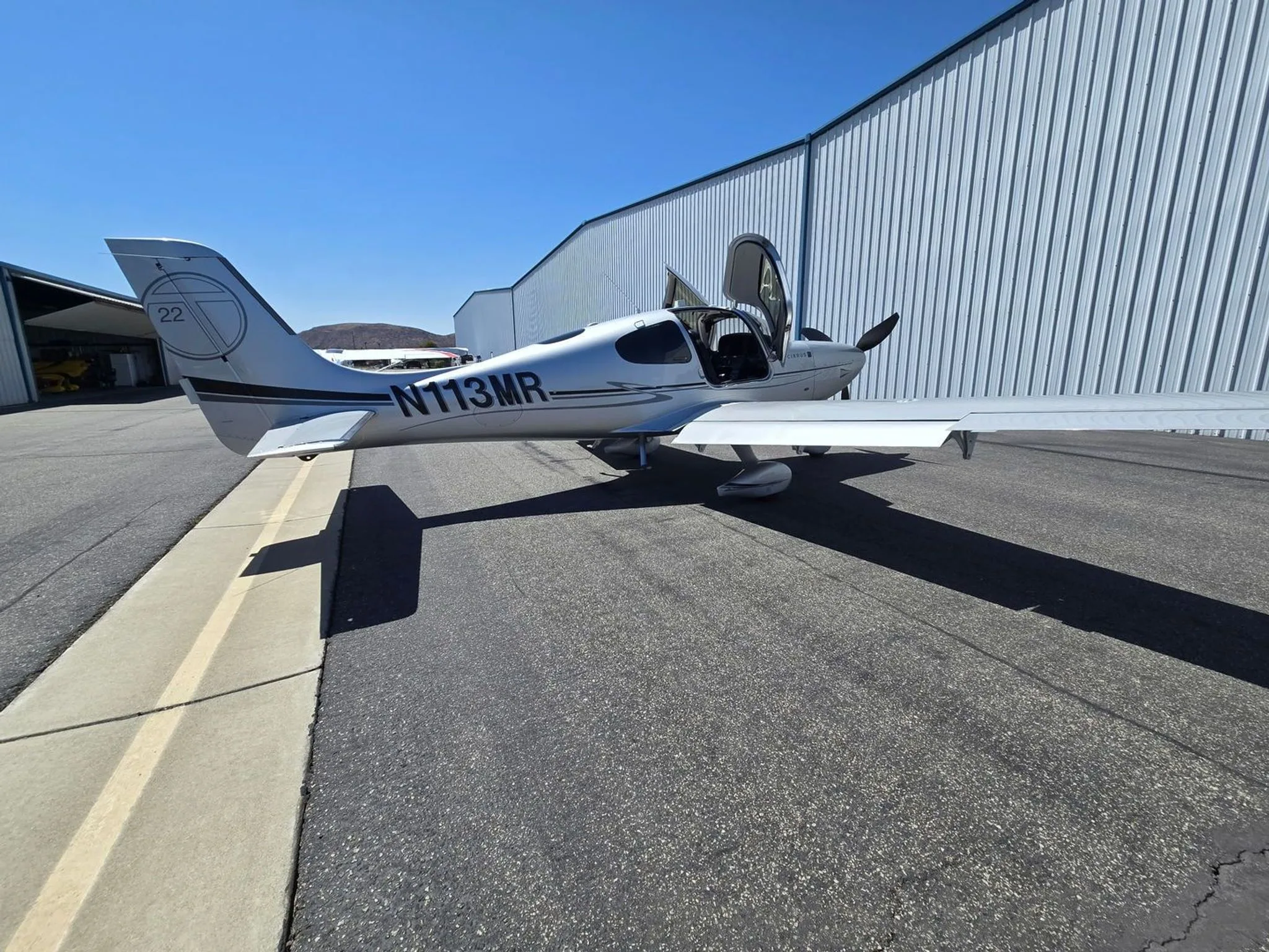


Free — save the SR22T to your watchlist and track it in one place.
More Cirrus SR22Tmanuals & documents
See all 21 →- Vantage 12 Pilot’s GuideV Speeds Reference
- Airworthiness Concern SheetAirworthiness Directives
- SERVICE BULLETIN HC-SB-30-390 Propeller - Spinner/Anti-ice Travel Tube InterferenceService Bulletins
- INSTRUCTIONS FOR INSTALLATION OF HARTZELL 4C1-F650A1/76C04(B)-0.6 PROPELLER ON CIRRUS SR22 AIRCRAFTMaintenance Manual
- INSTRUCTIONS FOR CONTINUED AIRWORTHINESS FOR HARTZELL 4C1-F650A1/76C04(B)-0.6 PROPELLER ON CIRRUS SR22T AIRCRAFTMaintenance Manual
- Supplemental Type Certificate SA03962ATSupplemental Type Certificate
- PILOT’S OPERATING HANDBOOK AND FAA APPROVED AIRPLANE FLIGHT MANUAL for the CIRRUS SR22Performance Data
- Continued Airworthiness Manual For Cirrus Design SR22 Series AirplanesMaintenance Manual
- Service Bulletin TAT SB10-01Service Bulletins
- Hartzell Engine Technologies Service Bulletin 033Service Bulletins
- SCHEDULE OF AIRWORTHINESS DIRECTIVESAirworthiness Directives
- Multi-Function Display Pilot’s GuidePerformance Data
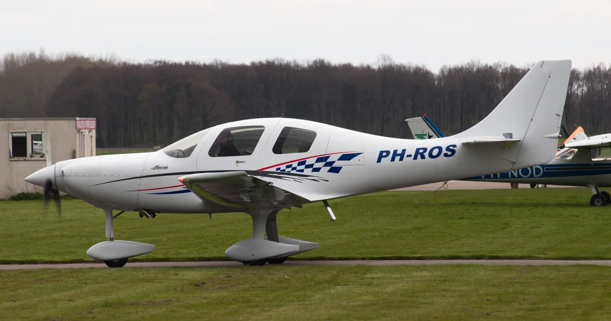
If you fly the Cirrus SR22T, you may also be researching these.



In this document
Normal Procedures
This section outlines the standard operating procedures for the Cirrus SR22, including preflight inspections, engine start, taxiing, takeoff, climb, cruise, descent, landing, and shutdown. Each procedure is detailed with specific actions and checks to ensure safe operation.
Airspeeds for Normal Operation
The checklist provides critical airspeed references for various phases of flight. For example, the takeoff rotation speed with flaps at 50% is 70 KIAS, while the best rate of climb at sea level is 101 KIAS. It also includes speeds for landing approaches and maximum recommended turbulent air penetration.
Preflight Inspection
A comprehensive preflight inspection checklist is included, detailing checks for cabin conditions, avionics, fuel quantity, and external aircraft components. Each item is crucial for ensuring the aircraft is ready for flight.
Before Takeoff
This section lists the necessary checks and settings before takeoff, such as confirming the fuel quantity, setting flaps to 50%, and ensuring all systems are operational. It emphasizes the importance of securing seat belts and verifying the CAPS handle.
Shutdown Procedures
The shutdown procedures detail the steps to safely power down the aircraft after landing, including turning off the fuel pump, setting the throttle to idle, and ensuring all switches are off.
Safety notes
- Always verify that the CAPS handle is pin removed before takeoff.
- Monitor engine parameters during startup and flight operations.
Full document text
PILOT’S CHECKLIST SR22 G1 OR G2 The procedures in this publication are abbreviated and derived from procedures in the FAA Approved Airplane Flight Manual and Pilot’s Operating Handbook (POH) P/N 13772-001 Revision A10 Release. These procedures do not supersede the procedures in the basic POH. In the event of conflict, the basic POH shall take precedence. COPYRIGHT © 2010 CIRRUS DESIGN CORPORATION DULUTH, MINNESOTA, USA ISSUED: July 2011 P/N 13728-001 Quick Reference Checklist for SR22 Aircraft Serials 0002 thru 2333, 2335 thru 2419, and 2421 thru 2437. P/N 13728-001 N - i Normal Procedures Table of Contents C I R R U S P I L O T ’ S C H E C K L I S T M O D E L S R 2 2 Primary Flight Display ......................................................................N-1 Airspeeds for Normal Operation ......................................................N-2 Preflight Inspection ..........................................................................N-3 Before Starting Engine .....................................................................N-6 Starting Engine ................................................................................N-7 Before Taxiing ..................................................................................N-7 Taxiing .............................................................................................N-7 Before Takeoff .................................................................................N-8 Normal Takeoff ................................................................................N-9 Short Field Takeoff...........................................................................N-9 Climb ................................................................................................N-9 Cruise...............................................................................................N-9 Cruise Leaning ..........................................................................N-10 Descent ..........................................................................................N-10 Before Landing...............................................................................N-10 Balked Landing/Go-Around............................................................N-10 After Landing..................................................................................N-11 Shutdown .......................................................................................N-11 July 2011 NORMAL PERFORMANCE ABNORMAL EMERGENCY NORMAL N - 1 P/N 13728-001 C I R R U S P I L O T C H E C K L I S T M O D E L S R 2 2 Primary Flight Display 10 20 20 ILS ILS TAS110 KTS GS 98 KTS OAT 11°C SAV DTK 020° 62.2 NM 00:26:18 KLWH BRG 352° 43.6 NM 00:17:52 ILS 108.10 CRS 020° Nav VLOC 1 Bearing GPS 1 Aux GPS 2 Range View 10 10 10 20 20 Power 74 24.0 M-BUS V V % E-BUS 24.0 80 90 110 120 9 10 1 037°/ 7 VSI Bug -500 FPM Alt Bug 4900 FT Baro Set 29.92" Hdg Bug 005° Hdg Sync AP RDY VS -20 -10 -5 0 5 10 20 4900 FT 5000 4900 4700 4600 29.92" 48 20 00 80 006 W E N S 15 12 24 30 33 6 3 21 0 LEGEND 1. Navigation & Avionics Configuration Buttons 2. Percent Power 3. Bus Voltages 4. Airspeed Window 5. Airspeed Tape 6. Autopilot Annunciations 7. Aircraft Reference Symbol 8. Bank Angle Indicator 9. Skid/Slip Indicator 10. Pitch Ladder 11. Flight Director Steering Command Bars 12. Vertical Deviation Indicator (VDI) 13. Altitude Tape 14. Altitude Window 15. Vertical Speed Indicator (VSI) 16. Brightness Control (BRT/DIM) 17. Mode and Display Selection 18. Wind Vector 19. Engine Information Data Block 20. Horizontal Situation Indicator (HSI) 21. Horizontal Deviation Indicator (HDI) 22. Air Data Block SR22_FM07_2221A 16 18 17 22 21 12 15 13 14 11 10 9 8 7 6 5 4 1 Tach 2400 RPM MAP 32.0 in-Hg FF 16.0 GPH Oil 49 PSI 3 2 1 17 19 20 July 2011 NORMAL PFD LEGEND P/N 13728-001 N - 2 C I R R U S P I L O T C H E C K L I S T M O D E L S R 2 2 Airspeeds for Normal Operation Takeoff Rotation: • Normal, Flaps 50%......................................................... 70 KIAS • Obstacle Clearance, Flaps 50% ..................................... 78 KIAS Enroute Climb, Flaps Up: • Normal................................................................... 110-120 KIAS • Best Rate of Climb, SL ................................................. 101 KIAS • Best Rate of Climb, 10,000’............................................ 95 KIAS • Best Angle of Climb, SL.................................................. 78 KIAS • Best Angle of Climb, 10,000’ .......................................... 82 KIAS Landing Approach: • Normal Approach, Flaps Up ...................................... 90-95 KIAS • Normal Approach, Flaps 50% ................................... 85-90 KIAS • Normal Approach, Flaps 100% ................................. 80-85 KIAS • Short Field, Flaps 100% (VREF).................................... 77 KIAS Go-Around, Flaps 50%: • Full Power....................................................................... 80 KIAS Maximum Recommended Turbulent Air Penetration: • 3400 Lb ........................................................................ 133 KIAS • 2900 Lb ........................................................................ 123 KIAS Maximum Demonstrated Crosswind • Takeoff or Landing ........................................................ 20 Knots July 2011 NORMAL AIRSPEEDS N - 3 P/N 13728-001 C I R R U S P I L O T C H E C K L I S T M O D E L S R 2 2 Preflight Inspection 1. Cabin a. Required Documents ................................................ On Board b. Avionics Power Switch ...................................................... OFF c. Bat 2 Master Switch ........................................................... ON d. PFD - Serials 0435 and subsequent with PFD...........Verify On e. Avionics Cooling Fan.................................................... Audible
Show full textShow less
f. Voltmeter ................................................................ 23-25 Volts g. Flap Position Light ............................................................OUT h. Bat 1 Master Switch ............................................................ ON i. Lights............................................................. Check Operation j. Stall Warning .....................................................................Test k. Fuel Quantity ................................................................. Check l. Fuel Selector .............................................. Select Fullest Tank m. Flaps ....................................................100%, Check Light ON n. Oil Annunciator.....................................................................On o. Bat 1 and 2 Master Switches ............................................ OFF SR20_FM04_1001 2 4 13 12 11 10 9 8 7 6 5 1 3 July 2011 NORMAL PREFLIGHT P/N 13728-001 N - 4 C I R R U S P I L O T C H E C K L I S T M O D E L S R 2 2 p. Alternate Static Source ............................................. NORMAL q. Circuit Breakers.....................................................................IN r. Fire Extinguisher ................................. Charged and Available s. Emergency Egress Hammer ...................................... Available t. CAPS Handle ..................................................... Pin Removed 2. Left Fuselage a. Door Lock...................................................................... Unlock b. COM 1 Antenna (top) ...................... Condition and Attachment c. Wing/Fuselage Fairing ................................................... Check d. COM 2 Antenna (underside) ........... Condition and Attachment e. Baggage Door ............................................Closed and Secure f. Static Button.............................................. Check for Blockage g. Parachute Cover ........................................Sealed and Secure 3. Empennage a. Tiedown Rope ............................................................. Remove b. Horizontal and Vertical Stabilizers............................. Condition c. Elevator and Tab ...............................Condition and Movement d. Rudder ................................................. Freedom of Movement e. Rudder Trim Tab................................... Condition and Security f. Attachment hinges, bolts and cotter pins ...................... Secure 4. Right Fuselage a. Static Button.............................................. Check for Blockage b. Wing/Fuselage Fairings ................................................. Check c. Door Lock...................................................................... Unlock 5. Right Wing Trailing Edge a. Flap and Rub Strips (if installed) .......... Condition and Security b. Aileron and Tab .................................Condition and Movement c. Aileron Gap Seal ......................................................... Security d. Hinges, actuation arm, bolts, and cotter pins ................ Secure 6. Right Wing Tip a. Tip .......................................................................... Attachment b. Strobe, Nav Light and Lens.................. Condition and Security (Continued on following page) July 2011 NORMAL PREFLIGHT N - 5 P/N 13728-001 C I R R U S P I L O T C H E C K L I S T M O D E L S R 2 2 c. Fuel Vent (underside) ..........................................Unobstructed 7. Right Wing Forward and Main Gear a. Leading Edge and Stall Strips................................... Condition b. Fuel Cap....................................... Check Quantity and Secure c. Fuel Drains (2 underside).............................Drain and Sample d. Wheel Fairings ......................Security, Accumulation of Debris e. Tire ............................................ Condition, Inflation, and Wear f. Wheel and Brakes ........Fluid Leaks, Evidence of Overheating, General Condition, and Security g. Chocks and Tiedown Ropes ....................................... Remove h. Cabin Air Vent .....................................................Unobstructed 8. Nose, Right Side a. Vortex Generator ....................................................... Condition b. Cowling .................................................... Attachments Secure c. Exhaust Pipe ..................... Condition, Security, and Clearance d. Transponder Antenna (underside)... Condition and Attachment e. Gascolator (underside)................ Drain for 3 seconds, Sample 9. Nose gear, Propeller, and Spinner a. Tow Bar ....................................................... Remove and Stow b. Strut........................................................................... Condition c. Wheel Fairing ........................Security, Accumulation of Debris d. Wheel and Tire.......................... Condition, Inflation, and Wear e. Propeller............................Condition (indentations, nicks, etc.) f. Spinner............................... Condition, Security, and Oil Leaks g. Air Inlets ..............................................................Unobstructed h. Alternator .................................................................. Condition 10. Nose, Left Side a. Landing Light............................................................. Condition b. Engine Oil......... Check 6-8 quarts, Leaks, Cap & Door Secure c. Cowling .................................................... Attachments Secure d. External Power ..................................................... Door Secure e. Vortex Generator ....................................................... Condition f. Exhaust Pipe(s)................. Condition, Security, and Clearance July 2011 NORMAL PREFLIGHT P/N 13728-001 N - 6 C I R R U S P I L O T C H E C K L I S T M O D E L S R 2 2 11. Left Main Gear and Forward Wing a. Wheel fairings .......................Security, Accumulation of Debris b. Tire ............................................ Condition, Inflation, and Wear c. Wheel and Brakes ........Fluid Leaks, Evidence of Overheating, General Condition, and Security d. Chocks and Tiedown Ropes ....................................... Remove e. Fuel Drains (2 underside).............................Drain and Sample f. Cabin Air Vent ..................................................... Unobstructed g. Fuel Cap....................................... Check Quantity and Secure h. Leading Edge and Stall Strips................................... Condition 12. Left Wing Tip a. Fuel Vent (underside).......................................... Unobstructed b. Pitot Mast (underside) ................. Cover Removed, Tube Clear c. Strobe, Nav Light and Lens.................. Condition and Security d. Tip ......................................................................... Attachment 13. Left Wing Trailing Edge a. Flap And Rub Strips (If installed) ......... Condition and Security b. Aileron .................................................. Freedom of movement c. Aileron Gap Seal ......................................................... Security d. Hinges, actuation arm, bolts, and cotter pins ................ Secure Before Starting Engine 1. Preflight Inspection ................................................... COMPLETED 2. Emergency Equipment ................................................ ON BOARD 3. Passengers......................................................................BRIEFED 4. Seats, Seat Belts, and Harnesses ................ ADJUST & SECURE July 2011 NORMAL BEFORE STARTING N - 7 P/N 13728-001 C I R R U S P I L O T C H E C K L I S T M O D E L S R 2 2 Starting Engine 1. External Power (If applicable) ........................................CONNECT 2. Brakes .................................................................................. HOLD 3. Bat Master Switches ............................................ON (Check Volts) 4. Strobe Lights ............................................................................. ON 5. Mixture ..........................................................................FULL RICH 6. Power Lever ........................................................ FULL FORWARD 7. Fuel Pump .................................................... PRIME, then BOOST 8. Propeller Area..................................................................... CLEAR 9. Power Lever ........................................................... OPEN ¼ INCH 10. Ignition Switch .......................START (Release after engine starts) 11. Power Lever ............................... RETARD (to maintain 1000 RPM) 12. Oil Pressure........................................................................CHECK 13. Alt Master Switches ................................................................... ON 14. Avionics Power Switch ............................................................... ON 15. Engine Parameters ........................................................ MONITOR 16. External Power (If applicable) ..................................DISCONNECT 17. Amp Meter/Indication..........................................................CHECK Before Taxiing 1. Flaps ..................................................................................UP (0%) 2. Radios/Avionics ......................................................AS REQUIRED 3. Cabin Heat/Defrost ................................................ AS REQUIRED 4. Fuel Selector .......................................................... SWITCH TANK Taxiing 1. Parking Brake ........................................................... .DISENGAGE 2. Brakes.................................................................................CHECK 3. HSI Orientation ...................................................................CHECK 4. Attitude Gyro.......................................................................CHECK 5. Turn Coordinator ................................................................CHECK July 2011 NORMAL START / TAXI P/N 13728-001 N - 8 C I R R U S P I L O T C H E C K L I S T M O D E L S R 2 2 Before Takeoff 1. Doors .............................................................................. LATCHED 2. CAPS Handle ................................................. Verify Pin Removed 3. Seat Belts and Shoulder Harness ................................... SECURE 4. Air Conditioner...........................................................AS DESIRED 5. Fuel Quantity ..................................................................CONFIRM 6. Fuel Selector ........................................................ FULLEST TANK 7. Fuel Pump ..........................................................................BOOST 8. Mixture....................................................................AS REQUIRED 9. Flaps............................................................... SET 50% & CHECK 10. Transponder............................................................................. SET 11. Autopilot..............................................................................CHECK 12. Navigation Radios/GPS ..........................................SET for Takeoff 13. Cabin Heat/Defrost .................................................AS REQUIRED 14. Brakes................................................................................... HOLD 15. Power Lever ................................................................... 1700 RPM 16. Alternator ............................................................................CHECK a. Pitot Heat ............................................................................ ON b. Navigation Lights................................................................. ON c. Landing Light....................................................................... ON d. Annunciator Lights .......................................................CHECK 17. Voltage................................................................................CHECK 18. Pitot Heat................................................................AS REQUIRED 19. Navigation Lights ....................................................AS REQUIRED 20. Landing Light ..........................................................AS REQUIRED 21. Magnetos.................................................... CHECK Left and Right a. RPM drop ≤150, difference between mags ≤75 RPM. 22. Engine Parameters .............................................................CHECK 23. Power Lever ................................................................... 1000 RPM 24. Flight Instruments, HSI, and Altimeter.................... CHECK & SET 25. Flight Controls .................................................FREE & CORRECT 26. Trim..............................................................................SET Takeoff 27. Autopilot...................................................................DISCONNECT July 2011 NORMAL BEFORE TAKEOFF N - 9 P/N 13728-001 C I R R U S P I L O T C H E C K L I S T M O D E L S R 2 2 Normal Takeoff 1. Brakes.................................... RELEASE (Steer with Rudder Only) 2. Power Lever ........................................................ FULL FORWARD 3. Engine Parameters .............................................................CHECK 4. Elevator Control ........................ ROTATE Smoothly at 70-73 KIAS 5. At 80 KIAS, Flaps ...................................................................... UP Short Field Takeoff 1. Flaps ........................................................................................ 50% 2. Brakes .................................................................................. HOLD 3. Power Lever ........................................................ FULL FORWARD 4. Mixture ..................................................................................... SET 5. Engine Parameters .............................................................CHECK 6. Brakes.................................... RELEASE (Steer with Rudder Only) 7. Elevator Control ..............................ROTATE Smoothly at 70 KIAS 8. Airspeed at Obstacle ......................................................... 78 KIAS Climb 1. Climb Power............................................................................. SET 2. Flaps ................................................................................ Verify UP 3. Mixture .............................................. LEAN as required for altitude 4. Engine Parameters .............................................................CHECK 5. Fuel Pump ..........................................................................BOOST Cruise 1. Fuel Pump ............................................................................... OFF 2. Cruise Power ........................................................................... SET 3. Mixture ................................................................ LEAN as required 4. Engine Parameters ........................................................ MONITOR 5. Fuel Flow and Balance .................................................. MONITOR July 2011 NORMAL TAKEOFF / CRUISE P/N 13728-001 N - 10 C I R R U S P I L O T C H E C K L I S T M O D E L S R 2 2 Cruise Leaning Descent 1. Altimeter .................................................................................. SET 2. Cabin Heat/Defrost .................................................AS REQUIRED 3. Landing Light ............................................................................. ON 4. Fuel System........................................................................CHECK 5. Mixture....................................................................AS REQUIRED 6. Brake Pressure ...................................................................CHECK Before Landing 1. Seat Belt and Shoulder Harness ..................................... SECURE 2. Fuel Pump ..........................................................................BOOST 3. Mixture....................................................................AS REQUIRED 4. Flaps.......................................................................AS REQUIRED 5. Autopilot..................................................................AS REQUIRED Balked Landing/Go-Around 1. Autopilot..................................................................... DISENGAGE 2. Power Lever ........................................................ FULL FORWARD 3. Flaps........................................................................................ 50% 4. Airspeed ....................................................................... 75-80 KIAS After clear of obstacles: 5. Flaps ......................................................................................... UP Mixture Description Exhaust Gas Temperature Best Power 75° F Rich Of Peak EGT Best Economy 50° F Lean Of Peak EGT July 2011 NORMAL LEAN / DESCENT N - 11 P/N 13728-001 C I R R U S P I L O T C H E C K L I S T M O D E L S R 2 2 After Landing 1. Power Lever ................................................................... 1000 RPM 2. Fuel Pump ............................................................................... OFF 3. Flaps .......................................................................................... UP 4. Transponder........................................................................... STBY 5. Lights ......................................................................AS REQUIRED 6. Pitot Heat................................................................................. OFF Shutdown 1. Fuel Pump (if used) ................................................................ OFF 2. Throttle ................................................................................... IDLE 3. Ignition Switch .................... CYCLE - MAG GROUNDING CHECK 4. Mixture ..............................................................................CUTOFF 5. All Switches ............................................................................. OFF 6. Magnetos ................................................................................. OFF 7. ELT ...........................................................TRANSMIT LIGHT OUT 8. Chocks, Tie-downs, Pitot Covers ............................AS REQUIRED July 2011 NORMAL LANDING P/N 13728-001 P - i Performance Table of Contents C I R R U S P I L O T ’ S C H E C K L I S T M O D E L S R 2 2 Takeoff Distance: 3400 LB...............................................................P-1 Takeoff Distance: 2900 LB...............................................................P-2 Cruise Performance .........................................................................P-3 Landing Distance .............................................................................P-5 Wind Components ...........................................................................P-6 Weight and Balance .........................................................................P-7 Loading Calculations ...................................................................P-7 Loading Data ...............................................................................P-8 Moment Limits .............................................................................P-8 Temperature Conversion .................................................................P-9 • Note • Aircraft with optional Air Conditioning System; Brake Horsepower is reduced by approximately 6 BHP. July 2011 NORMAL PERFORMANCE ABNORMAL EMERGENCY PERFORMANCE P - 1 P/N 13728-001 C I R R U S P I L O T C H E C K L I S T M O D E L S R 2 2 Takeoff Distance: 3400 LB WEIGHT = 3400 LB Speed at Liftoff = 73 KIAS Speed over 50 Ft. Obstacle = 78 KIAS Flaps - 50% · Takeoff Pwr · Dry Paved Headwind: Subtract 10% for each 12 knots headwind. Tailwind: Add 10% for each 2 knots tailwind up to 10 knots. Runway Slope: Ref. Factors. Dry Grass: Add 20% to Ground Roll. Wet Grass: Add 30% to Ground Roll. Air Conditioner: Add 100' to ground roll and 150' to distance over 50' obstacle if Air Conditioner if ON during takeoff. PRESS ALT FT DISTANCE FT TEMPERATURE ~ °C 0 10 20 30 40 ISA SL Grnd Roll 917 990 1067 1146 1229 1028 50 ft 1432 1539 1650 1764 1883 1594 1000 Grnd Roll 1011 1092 1176 1264 1355 1117 50 ft 1574 1691 1813 1939 2069 1728 2000 Grnd Roll 1116 1206 1299 1395 1496 1215 50 ft 1732 1861 1995 2133 2276 1874 3000 Grnd Roll 1234 1332 1435 1542 1653 1323 50 ft 1907 2049 2196 2349 2507 2035 4000 Grnd Roll 1365 1474 1588 1706 1829 1441 50 ft 2102 2259 2422 2590 2764 2212 5000 Grnd Roll 1512 1633 1758 1889 2025 1572 50 ft 2320 2493 2673 2858 3051 2407 6000 Grnd Roll 1676 1810 1950 2095 2245 1717 50 ft 2564 2755 2953 3159 3371 2622 7000 Grnd Roll 1861 2009 2164 2325 2492 1877 50 ft 2837 3048 3267 3494 3729 2859 8000 Grnd Roll 2068 2233 2405 2584 2770 2054 50 ft 3142 3376 3619 3871 4131 3122 9000 Grnd Roll 2302 2485 2677 2875 3082 2250 50 ft 3485 3744 4014 4293 4581 3412 10000 Grnd Roll 2564 2769 2982 3204 3434 2468 50 ft 3870 4158 4457 4767 5088 3733 July 2011 PERFORMANCE TAKEOFF 3400 LB P/N 13728-001 P - 2 C I R R U S P I L O T C H E C K L I S T M O D E L S R 2 2 Takeoff Distance: 2900 LB WEIGHT = 2900 LB Speed at Liftoff = 70 KIAS Speed over 50 Ft Obstacle = 74 KIAS Flaps - 50% · Takeoff Pwr · Dry Paved Headwind: Subtract 10% for each 12 knots headwind. Tailwind: Add 10% for each 2 knots tailwind up to 10 knots. Runway Slope: Ref. Factors. Dry Grass: Add 20% to Ground Roll. Wet Grass: Add 30% to Ground Roll. Air Conditioner: Add 100' to ground roll and 150' to distance over 50' obstacle if Air Conditioner if ON during takeoff. PRESS ALT FT DISTANCE FT TEMPERATURE ~ °C 0 10 20 30 40 ISA SL Grnd Roll 610 659 710 763 818 684 50 ft 971 1043 1118 1195 1275 1080 1000 Grnd Roll 673 727 783 841 902 743 50 ft 1066 1146 1228 1313 1401 1170 2000 Grnd Roll 743 802 864 929 995 809 50 ft 1173 1260 1351 1444 1541 1269 3000 Grnd Roll 821 887 955 1026 1100 880 50 ft 1292 1388 1487 1590 1697 1378 4000 Grnd Roll 908 981 1057 1135 1217 959 50 ft 1424 1530 1639 1753 1871 1498 5000 Grnd Roll 1006 1086 1170 1257 1348 1046 50 ft 1571 1688 1809 1935 2065 1630 6000 Grnd Roll 1116 1205 1298 1394 1494 1143 50 ft 1736 1865 1999 2138 2281 1775 7000 Grnd Roll 1238 1337 1440 1547 1659 1249 50 ft 1920 2063 2211 2365 2523 1936 8000 Grnd Roll 1376 1486 1601 1720 1843 1367 50 ft 2127 2285 2449 2619 2795 2113 9000 Grnd Roll 1532 1654 1781 1914 2051 1498 50 ft 2359 2534 2716 2904 3099 2309 10000 Grnd Roll 1707 1843 1985 2132 2285 1643 50 ft 2619 2814 3016 3225 3441 2527 July 2011 PERFORMANCE TAKEOFF 2900 LB P - 3 P/N 13728-001 C I R R U S P I L O T C H E C K L I S T M O D E L S R 2 2 Cruise Performance • Note • Subtract 10 KTAS if nose wheel pant and fairing removed. Lower KTAS by 10% if nose and main wheel pants & fairings are removed. Aircraft with optional Air Conditioning System - Cruise performance is reduced by 2 knots. For maximum performance, the air-conditioner should be off. Conditions: • Cruise Weight ............................................................................................ 2900 LB • Winds ............................................................................................................... Zero • Shaded Cells: Cruise Pwr above 85% not recommended. Press Alt ISA - 30°C ISA ISA + 30°C RPM MAP PWR KTAS GPH PWR KTAS GPH PWR KTAS GPH 2000 2700 27.4 103% 186 24.6 98% 186 23.3 93% 181 22.0 2600 27.4 99% 183 23.5 94% 183 22.2 89% 178 21.5 2500 27.4 93% 179 22.1 88% 179 20.9 84% 174 20.8 2500 26.4 89% 176 21.1 84% 176 19.9 80% 171 20.2 2500 25.4 84% 173 20.0 80% 173 19.0 76% 168 19.5 2500 24.4 80% 170 19.0 76% 170 18.0 72% 165 18.8 2500 23.4 76% 167 18.0 72% 167 17.0 68% 162 18.1 4000 2700 25.4 96% 185 22.9 91% 185 21.6 87% 180 20.8 2600 25.4 92% 182 21.9 87% 182 20.7 83% 177 20.6 2500 25.4 87% 178 20.6 82% 178 19.5 78% 173 19.9 2500 24.4 82% 175 19.5 78% 175 18.5 74% 170 19.2 2500 23.4 78% 172 18.5 74% 172 17.5 70% 167 18.5 2500 22.4 73% 169 17.4 69% 169 16.5 66% 163 17.7 2500 21.4 69% 165 16.4 65% 165 15.5 62% 159 16.9 6000 2700 23.5 89% 184 21.2 85% 184 20.1 81% 179 19.6 2600 23.5 85% 181 20.3 81% 181 19.2 77% 176 19.1 2500 23.5 80% 177 19.1 76% 177 18.1 72% 172 18.3 2500 22.5 76% 174 18.1 72% 174 17.1 68% 169 17.6 2500 21.5 72% 170 17.0 68% 170 16.1 64% 165 16.9 2500 20.5 67% 166 15.9 64% 166 15.1 60% 161 16.1 2500 19.5 63% 162 14.9 59% 162 14.1 56% 157 15.3 July 2011 PERFORMANCE CRUISE P/N 13728-001 P - 4 C I R R U S P I L O T C H E C K L I S T M O D E L S R 2 2 8000 2700 21.7 83% 183 19.7 78% 183 18.6 75% 178 17.7 2600 21.7 79% 180 18.8 75% 180 17.8 71% 175 17.0 2500 21.7 75% 176 17.7 71% 176 16.8 67% 171 16.0 2500 20.7 70% 172 16.7 66% 172 15.8 63% 167 15.0 2500 19.7 66% 168 15.6 62% 168 14.8 59% 163 14.0 2500 18.7 61% 163 14.5 58% 163 13.8 55% 158 13.1 2500 17.7 57% 159 13.5 54% 159 12.8 51% 153 12.1 10000 2700 20.0 77% 182 18.2 73% 182 17.3 69% 176 16.4 2600 20.0 71% 177 17.0 68% 177 16.1 64% 172 15.3 2500 20.0 67% 173 16.0 64% 173 15.1 61% 167 14.4 2500 19.0 63% 168 14.9 59% 168 14.1 56% 163 13.4 2500 18.0 58% 163 13.8 55% 163 13.1 52% 158 12.5 2500 17.0 54% 158 12.8 51% 158 12.1 48% 153 11.5 12000 2700 18.5 71% 180 16.9 67% 180 16.0 64% 175 15.2 2600 18.5 68% 177 16.2 64% 177 15.3 61% 172 14.5 2500 18.5 64% 173 15.2 60% 173 14.4 58% 167 13.7 2500 17.5 59% 168 14.1 56% 168 13.4 53% 162 12.7 2500 16.5 55% 162 13.0 52% 162 12.3 49% 157 11.7 2500 15.5 50% 156 12.0 48% 156 11.3 45% 151 10.8 14000 2700 17.1 66% 178 15.6 62% 178 14.8 59% 173 14.1 2600 17.1 63% 175 14.9 60% 175 14.1 57% 170 13.5 2500 17.1 59% 171 14.1 56% 171 13.3 53% 165 12.7 2500 16.1 55% 165 13.0 52% 165 12.3 49% 159 11.7 2500 15.1 50% 159 11.9 47% 159 11.2 45% 153 10.7 16000 2700 15.8 61% 176 14.5 58% 176 13.7 55% 171 13.0 2600 15.8 58% 173 13.8 55% 173 13.1 52% 167 12.5 2500 15.8 55% 168 13.0 52% 168 12.3 49% 163 11.7 2500 14.8 50% 162 11.9 47% 162 11.3 45% 156 10.7 17000 2700 15.2 59% 175 13.9 55% 175 13.2 53% 169 12.5 2600 15.2 56% 171 13.3 53% 171 12.6 50% 166 12.0 2500 15.2 53% 167 12.5 50% 167 11.9 47% 162 11.3 2500 14.2 48% 160 11.4 45% 160 10.8 43% 155 10.3 Press Alt ISA - 30°C ISA ISA + 30°C RPM MAP PWR KTAS GPH PWR KTAS GPH PWR KTAS GPH July 2011 PERFORMANCE CRUISE P - 5 P/N 13728-001 C I R R U S P I L O T C H E C K L I S T M O D E L S R 2 2 Landing Distance WEIGHT = 3400 LB Speed over 50 Ft Obstacle = 77 KIAS Flaps - 100%· Idle · Dry, Level Paved Surface Headwind: Subtract 10% for each 13 knots headwind. Tailwind: Add 10% for each 2 knots tailwind up to 10 knots. Runway Slope: Ref. Factors. Dry Grass: Add 20% to Ground Roll Wet Grass: Add 60% to Ground Roll PRESS ALT FT DISTANCE FT TEMPERATURE ~ °C 0 10 20 30 40 ISA SL Grnd Roll 1082 1121 1161 1200 1240 1141 Total 2262 2316 2372 2428 2485 2344 1000 Grnd Roll 1122 1163 1204 1245 1286 1175 Total 2317 2374 2433 2492 2551 2391 2000 Grnd Roll 1163 1206 1248 1291 1334 1210 Total 2375 2436 2497 2559 2621 2441 3000 Grnd Roll 1207 1251 1295 1339 1384 1247 Total 2437 2501 2565 2630 2696 2493 4000 Grnd Roll 1252 1298 1344 1390 1436 1285 Total 2503 2569 2637 2705 2774 2548 5000 Grnd Roll 1300 1348 1395 1443 1490 1324 Total 2572 2642 2713 2785 2857 2605 6000 Grnd Roll 1350 1399 1449 1498 1547 1365 Total 2645 2719 2794 2869 2945 2665 7000 Grnd Roll 1402 1453 1504 1556 1607 1408 Total 2723 2800 2879 2958 3038 2728 8000 Grnd Roll 1456 1509 1563 1616 1669 1452 Total 2805 2887 2969 3052 3136 2794 9000 Grnd Roll 1513 1569 1624 1679 1735 1497 Total 2892 2978 3064 3152 3240 2863 10000 Grnd Roll 1573 1630 1688 1746 1803 1545 Total 2984 3074 3165 3257 3350 2936 July 2011 PERFORMANCE LANDING P/N 13728-001 P - 6 C I R R U S P I L O T C H E C K L I S T M O D E L S R 2 2 Wind Components • Note • The maximum demonstrated crosswind is 20 knots. Value not considered limiting. Conditions: Example: (See Chart ) • Runway Heading .......................... 10° Wind/Flight Path Angle ................. 50° • Wind Direction .............................. 60° Crosswind Component......... 12 Knots • Wind Velocity ........................15 Knots Headwind Component ......... 10 Knots 10 10 Headwind Tailwind WIND COMPONENTS - KNOTS 0 ANGLE BETWEEN WIND DIRECTION AND FLIGHT PATH SR2_FM05_1014 40 30 20 10 0 -10 -20 20 30 40 50 60 70 80 90 100 110 120 30 40 10 20 130 140 150 160 170 180 20 30 40 50 CROSSWIND COMPONENT ~ KNOTS VELOCITY ~ KNOTS WIND July 2011 PERFORMANCE WIND COMPONENTS P - 7 P/N 13728-001 C I R R U S P I L O T C H E C K L I S T M O D E L S R 2 2 Weight and Balance Loading Calculations For Moment/1000, refer to Loading Data table on following page. Calculation Instructions 1. Enter the current basic empty weight and moment from the aircraft’s Weight and Balance Record. 2. Enter the total weight and moment/1000 for the front seat occupants from the adjacent Loading Data Table. 3. Enter the total weight and moment/1000 for the rear seat occupants from the adjacent Loading Data Table. 4. Enter the total weight and moment/1000 for the baggage from the adjacent Loading Data Table. 5. If desired, subtotal the weight and moment/1000 entries from steps 1 - 4. 6. Enter the weight and moment/1000 of usable fuel loaded on the airplane. 7. Subtotal the weight and moment/1000. 8. Enter values for typical start, taxi, and run-up operations of 9 pounds at an average moment\1000 of 1.39. 9. Subtract step 8 weight and moment/1000 from the Ramp Weight to determine the Takeoff Weight and moment/1000. a. Verify Takeoff Weight does not exceed the 3400 pounds. b. Verify Moment/1000 does falls between the interpolated minimum and maximum values listed on the adjacent Moment Limits Table. Description Weight Moment/1000 1. Empty Weight Includes unusable fuel and full oil 2. Front Seats Occupants Pilot and Passenger 3. Rear Seats Occupants 4. Baggage 130 lb maximum 5. Zero Fuel Condition Subtotal items 1 thru 4 6. Fuel Load 81 Gallon @6.0 lb/gal. maximum 7. Ramp Weight Subtotal items 5 and 6 8. Fuel for start, taxi, and runup Normally 9 lb at avg. mmnt of 1394 - - 9. Takeoff Weight Subtract Item 8 from item 7 July 2011 PERFORMANCE WEIGHT AND BALANCE P/N 13728-001 P - 8 C I R R U S P I L O T C H E C K L I S T M O D E L S R 2 2 Loading Data To complete Loading Calculations, use this table to determine the Moment/1000. * 130 lb Maximum ** 81 Gallon Usable Moment Limits Use this table to determine if Loading Calculations are within limits. Weight LB Fwd Pass FS 143.5 Aft Pass FS 180.0 Baggage FS 208.0 Fuel FS 154.9 Weight LB Fwd Pass FS 143.5 Aft Pass FS 180.0 Fuel FS 154.9 20 2.87 3.60 4.16 3.10 260 37.31 46.80 40.27 40 5.74 7.20 8.32 6.20 280 40.18 50.40 43.37 60 8.61 10.80 12.48 9.29 300 43.05 54.00 46.47 80 11.48 14.40 16.64 12.39 320 45.92 57.60 49.57 100 14.35 18.00 20.80 15.49 340 48.79 61.20 52.67 120 17.22 21.60 24.96 18.59 360 51.66 64.80 55.76 140 20.09 25.20 (27.04)* 21.69 380 54.53 68.40 58.86 160 22.96 28.80 24.78 400 57.40 72.00 61.96 180 25.83 32.40 27.88 420 60.27 75.60 65.06 200 28.70 36.00 30.98 440 63.14 79.20 68.16 220 31.57 39.60 34.08 460 71.25 240 34.44 43.20 37.18 486** 75.28 Weight LB MInimum Moment /1000 Maximum Moment/1000 Weight LB MInimum Moment /1000 Maximum Moment/1000 2200 304 326 2850 398 422 2250 311 333 2900 406 430 2300 318 341 2950 414 437 2350 326 348 3000 421 444 2400 333 355 3050 429 452 2450 340 363 3100 437 459 2500 347 370 3150 444 467 2550 354 378 3200 452 474 2600 362 385 3250 460 481 2650 369 392 3300 467 489 2700 375 400 3350 475 496 2750 383 407 3400 483 504 2800 390 415 July 2011 PERFORMANCE WEIGHT AND BALANCE P - 9 P/N 13728-001 C I R R U S P I L O T C H E C K L I S T M O D E L S R 2 2 Temperature Conversion To convert from Celsius (°C) to Fahrenheit (°F), find, in the shaded columns, the number representing the temperature value (°C) to be converted. The equivalent Fahrenheit temperature is read to the right. EXAMPLE: 38°C = 100°F. To convert from Fahrenheit (°F) to Celsius (°C), find in the shaded columns area, the number representing the temperature value (°F) to be converted. The equivalent Celsius temperature is read to the left. EXAMPLE: 38°F = 3°C. Temp to Convert °C or °F Temp to Convert °C or °F Temp to Convert °C or °F °C °F °C °F °C °F -50 -58 -72 -17 2 36 17 62 144 -49 -56 -69 -16 4 39 18 64 147 -48 -54 -65 -14 6 43 19 66 151 -47 -52 -62 -13 8 46 20 68 154 -46 -50 -58 -12 10 50 21 70 158 -44 -48 -54 -11 12 54 22 72 162 -43 -46 -51 -10 14 57 23 74 165 -42 -44 -47 -9 16 61 24 76 169 -41 -42 -44 -8 18 64 26 78 172 -40 -40 -40 -7 20 68 27 80 176 -39 -38 -36 -6 22 72 28 82 180 -38 -36 -33 -4 24 75 29 84 183 -37 -34 -29 -3 26 79 30 86 187 -36 -32 -26 -2 28 82 31 88 190 -34 -30 -22 -1 30 86 32 90 194 -33 -28 -18 0 32 90 33 92 198 -32 -26 -15 1 34 93 34 94 201 -31 -24 -11 2 36 97 36 96 205 -30 -22 -8 3 38 100 37 98 208 -29 -20 -4 4 40 104 38 100 212 -28 -18 0 6 42 108 39 102 216 -27 -16 3 7 44 111 40 104 219 -26 -14 7 8 46 115 41 106 223 -24 -12 10 9 48 118 42 108 226 -23 -10 14 10 50 122 43 110 230 -22 -8 18 11 52 126 44 112 234 -21 -6 21 12 54 129 46 114 237 -20 -4 25 13 56 133 47 116 241 -19 -2 28 14 58 136 48 118 244 -18 0 32 16 60 140 49 120 248 July 2011 PERFORMANCE TEMP CONVERSION P/N 13728-001 A - i Abnormal Procedures Table of Contents C I R R U S P I L O T ’ S C H E C K L I S T M O D E L S R 2 2 Ground Procedures..........................................................................A-1 Brake Failure During Taxi............................................................A-1 Aborted Takeoff ...........................................................................A-1 In-Flight Procedures.........................................................................A-2 Inadvertent Icing Encounter.........................................................A-2 Inadvertent IMC Encounter..........................................................A-2 Door Open In Flight .....................................................................A-2 Landing Procedures .........................................................................A-3 Landing With Failed Brakes.........................................................A-3 Landing With Flat Tire .................................................................A-3 System Malfunctions ........................................................................A-4 Alternator Failure .........................................................................A-4 Engine Indicating System Failure ................................................A-4 LOW VOLTS Warning Light Illuminated ......................................A-5 Communications Failure..............................................................A-5 Pitot Static Malfunction ................................................................A-5 Electric Trim/Autopilot Failure......................................................A-5 July 2011 NORMAL PERFORMANCE ABNORMAL EMERGENCY ABNORMAL A - 1 P/N 13728-001 C I R R U S P I L O T C H E C K L I S T M O D E L S R 2 2 Ground Procedures Brake Failure During Taxi 1. Engine Power..........................................................AS REQUIRED 2. Directional Control ............................... MAINTAIN WITH RUDDER 3. Brake Pedal(s) ...................................................................... PUMP If directional control can not be maintained: 4. Mixture ..............................................................................CUTOFF Aborted Takeoff 1. Power Lever ............................................................................ IDLE 2. Brakes.....................................................................AS REQUIRED July 2011 ABNORMAL GROUND P/N 13728-001 A - 2 C I R R U S P I L O T C H E C K L I S T M O D E L S R 2 2 In-Flight Procedures Inadvertent Icing Encounter 1. Pitot Heat................................................................................... ON 2. Exit icing conditions. Turn back or change altitude. 3. Cabin Heat..................................................................... MAXIMUM 4. Windshield Defrost ..................................................... FULL OPEN 5. Alternate Induction Air ............................................................... ON Inadvertent IMC Encounter 1. Airplane Control........................ Establish Straight and Level Flight 2. Autopilot................................Engage to hold Heading and Altitude 3. Heading ..................................................Reset to initiate 180° turn Door Open In Flight 1. Airplane Control..............................................................MAINTAIN July 2011 ABNORMAL IN FLIGHT A - 3 P/N 13728-001 C I R R U S P I L O T C H E C K L I S T M O D E L S R 2 2 Landing Procedures Landing With Failed Brakes One brake inoperative 1. Land on the side of runway corresponding to the inoperative brake. 2. Maintain directional control using rudder and working brake. Both brakes inoperative 1. Divert to the longest, widest runway with the most direct headwind. 2. Land on downwind side of the runway. 3. Use the rudder for obstacle avoidance. 4. Perform Emergency Engine Shutdown on Ground checklist. Landing With Flat Tire Main Gear 1. Land on the side of the runway corresponding to the good tire. 2. Maintain directional control with the brakes and rudder. 3. Do not taxi. Stop the airplane and perform a normal engine shutdown. Nose Gear 1. Land in the center of the runway. 2. Hold the nosewheel off the ground as long as possible. 3. Do not taxi. Stop the airplane and perform a normal engine shutdown. July 2011 ABNORMAL LANDING P/N 13728-001 A - 4 C I R R U S P I L O T C H E C K L I S T M O D E L S R 2 2 System Malfunctions Alternator Failure ALT 1 Light Steady 1. ALT 1 Master Switch................................................................ OFF 2. Alternator 1 Circuit Breaker ............................CHECK and RESET 3. ALT 1 Master Switch.................................................................. ON If alternator does not reset: 4. Switch off unnecessary equipment on Main Bus 1, Main Bus 2, and the Non-Essential Buses to reduce loads. Monitor voltage. 5. ALT 1 Master Switch................................................................ OFF 6. Land as soon as practical. ALT 1 Light Flashing Serials 0002 thru 1643 and 1645 thru 1666: 1. Ammeter Switch .....................................................................BATT 2. If charging rate is greater than 30 amps, reduce load on Main Bus 1, Main Bus 2, and Non-Essential buses. 3. Monitor ammeter until battery charge rate is less than 15 amps. 4. When battery charge rate is within limits, add loads as necessary for flight conditions. ALT 2 Light Steady 1. ALT 2 Master Switch................................................................ OFF 2. Alternator 2 Circuit Breaker ............................CHECK and RESET 3. ALT 2 Master Switch.................................................................. ON If alternator does not reset: 4. Switch off unnecessary equipment on Main Bus 1, Main Bus 2, and Non-Essential Buses to reduce loads. 5. ALT 2 Master Switch................................................................ OFF 6. Land as soon as practical. Engine Indicating System Failure Serials 1644, 1663 and Subsequent: 1. ANNUN / ENGINE INST Circuit Breaker ............................... Cycle 2. Land as soon as practical. July 2011 ABNORMAL SYSTEMS A - 5 P/N 13728-001 C I R R U S P I L O T C H E C K L I S T M O D E L S R 2 2 LOW VOLTS Warning Light Illuminated 1. Land as soon as practical. Communications Failure 1. Switches, Controls ..............................................................CHECK 2. Frequency........................................................................ CHANGE 3. Circuit Breakers ..................................................................CHECK 4. Headset ........................................................................... CHANGE 5. Hand Held Microphone..................................................CONNECT Pitot Static Malfunction Static Source Blocked 1. Pitot Heat................................................................................... ON 2. Alternate Static Source......................................................... OPEN Pitot Tube Blocked 1. Pitot Heat................................................................................... ON Electric Trim/Autopilot Failure 1. Airplane Control..........................................MAINTAIN MANUALLY 2. Autopilot (if engaged)..................................................... Disengage If Problem Is Not Corrected: 3. Circuit Breakers ................................................ PULL AS Required • PITCH TRIM • ROLL TRIM • AUTOPILOT 4. Power Lever ............................................................AS REQUIRED 5. Control Yoke .................................MANUALLY HOLD PRESSURE 6. Land as soon as practical. July 2011 ABNORMAL SYSTEMS P/N 13728-001 E - i Emergency Procedures Table of Contents C I R R U S P I L O T ’ S C H E C K L I S T M O D E L S R 2 2 Airspeeds For Emergency Operations .............................................E-1 Maximum Glide............................................................................E-1 Memory Items..............................................................................E-1 Ground Emergencies .......................................................................E-2 Engine Fire During Start ..............................................................E-2 Emergency Engine Shutdown On Ground ..................................E-2 Emergency Ground Egress .........................................................E-2 In-Flight Emergencies ......................................................................E-3 Engine Failure On Takeoff (Low Altitude)....................................E-3 Engine Failure In Flight................................................................E-3 Engine Airstart .............................................................................E-4 Engine Partial Power Loss ..........................................................E-4 Low Oil Pressure .........................................................................E-4 Propeller Governor Failure ..........................................................E-4 Smoke and Fume elimination ......................................................E-5 Engine Fire In Flight ....................................................................E-5 Wing Fire In Flight .......................................................................E-5 Cabin Fire In Flight ......................................................................E-5 Emergency Descent ....................................................................E-6 Inadvertent Spiral Dive During IMC Flight ...................................E-6 Inadvertent Spin Entry .................................................................E-6 CAPS Deployment.......................................................................E-7 Landing Emergencies ......................................................................E-8 Emergency Landing Without Engine Power ................................E-8 Ditching........................................................................................E-8 Landing Without Elevator Control................................................E-8 System Malfunctions ........................................................................E-9 PFD - Loss of Air Data.................................................................E-9 PFD - Loss of Attitude Data.........................................................E-9 Power Lever Linkage Failure.......................................................E-9 Annunciator Panel / MFD EMAX Messages ..................................E-10 Circuit Breaker Panel .....................................................................E-11 July 2011 NORMAL PERFORMANCE ABNORMAL EMERGENCY E - 1 P/N 13728-001 C I R R U S P I L O T C H E C K L I S T M O D E L S R 2 2 Airspeeds For Emergency Operations Maneuvering Speed: • 3400 lb.......................................................................... 133 KIAS Best Glide: • 3400 lb............................................................................ 88 KIAS • 2900 lb............................................................................ 87 KIAS Emergency Landing (Engine-Out) • Flaps Up ......................................................................... 90 KIAS • Flaps 50% ...................................................................... 85 KIAS • Flaps 100% .................................................................... 80 KIAS Maximum Glide Glide Ratio ≈ 9.6 : 1 Memory Items Checklist steps emphasized by underlining such as the example below, should be memorized for accomplishment without reference to the procedure. 1. Best Glide Speed........................................................ ESTABLISH 14000 12000 10000 8000 6000 2000 4000 0 6 8 10 12 14 16 18 4 2 20 0 GROUND DISTANCE - NAUTICAL MILES HEIGHT ABOVE GROUND - FEET SR2_FM03_1391 July 2011 EMERGENCY AIRSPEEDS P/N 13728-001 E - 2 C I R R U S P I L O T C H E C K L I S T M O D E L S R 2 2 Ground Emergencies Engine Fire During Start 1. Mixture.............................................................................. CUTOFF 2. Fuel Pump ............................................................................... OFF 3. Fuel Selector ........................................................................... OFF 4. Power Lever .................................................................. FORWARD 5. Starter.................................................................................CRANK 6. If flames persist, perform Emergency Engine Shutdown on Ground and Emergency Ground Egress checklists. Emergency Engine Shutdown On Ground 1. Power Lever ............................................................................ IDLE 2. Fuel Pump (if used) ................................................................. OFF 3. Mixture.............................................................................. CUTOFF 4. Fuel Selector ........................................................................... OFF 5. Ignition Switch ......................................................................... OFF 6. Bat-Alt Master Switches .......................................................... OFF Emergency Ground Egress 1. Engine ....................................................................... SHUTDOWN 2. Seat belts........................................................................RELEASE 3. Airplane .................................................................................. EXIT July 2011 EMERGENCY GROUND E - 3 P/N 13728-001 C I R R U S P I L O T C H E C K L I S T M O D E L S R 2 2 In-Flight Emergencies Engine Failure On Takeoff (Low Altitude) 1. Best Glide or Landing Speed (as appropriate) ........... ESTABLISH 2. Mixture .............................................................................. CUTOFF 3. Fuel Selector ........................................................................... OFF 4. Ignition Switch ......................................................................... OFF 5. Flaps .......................................................................AS REQUIRED If time permits: 6. Power Lever ............................................................................ IDLE 7. Fuel Pump ............................................................................... OFF 8. Bat-Alt Master Switches .......................................................... OFF 9. Seat Belts ......................................................ENSURE SECURED Engine Failure In Flight 1. Best Glide Speed........................................................ ESTABLISH 2. Mixture ....................................................................AS REQUIRED 3. Fuel Selector ........................................................SWITCH TANKS 4. Fuel Pump ..........................................................................BOOST 5. Alternate Induction Air ............................................................... ON 6. Air Conditioner (if installed) ..................................................... OFF 7. Ignition Switch ........................................................ CHECK, BOTH 8. If no start, perform Engine Airstart or Forced Landing checklist. July 2011 EMERGENCY IN FLIGHT P/N 13728-001 E - 4 C I R R U S P I L O T C H E C K L I S T M O D E L S R 2 2 Engine Airstart 1. Bat Master Switches.................................................................. ON 2. Power Lever ..................................................................... ½” OPEN 3. Mixture.................................................................RICH, AS REQ’D 4. Fuel Selector ........................................................SWITCH TANKS 5. Ignition Switch .......................................................................BOTH 6. Fuel Pump ..........................................................................BOOST 7. Alternate Induction Air ............................................................... ON 8. Alt Master Switches ................................................................. OFF 9. Starter (Propeller not Windmilling) .................................. ENGAGE 10. Power Lever ....................................................... slowly INCREASE 11. Alt Master Switches ................................................................... ON 12. If no start, perform Forced Landing checklist. Engine Partial Power Loss 1. Air Conditioner (if installed) ..................................................... OFF 2. Fuel Pump ..........................................................................BOOST 3. Fuel Selector ........................................................SWITCH TANKS 4. Mixture..............................CHECK appropriate for flight conditions 5. Power Lever ....................................................................... SWEEP 6. Alternate Induction Air ............................................................... ON 7. Ignition Switch ...................................................... BOTH, L, then R 8. Land as soon as practical. Low Oil Pressure 1. Power Lever ................................................ MINIMUM REQUIRED 2. Land as soon as possible. Propeller Governor Failure Propeller Rpm Will Not Increase 1. Oil Pressure........................................................................CHECK 2. Land as soon as practical. Propeller Overspeeds Or Will Not Decrease 1. Power Lever ................................. ADJUST (to keep RPM in limits) 2. Airspeed ........................................................ REDUCE to 90 KIAS 3. Land as soon as practical. July 2011 EMERGENCY POWER LOSS E - 5 P/N 13728-001 C I R R U S P I L O T C H E C K L I S T M O D E L S R 2 2 Smoke and Fume elimination 1. Air Conditioner (if installed) ..................................................... OFF 2. Temperature Selector ........................................................... COLD 3. Vent Selector ........................ FEET/PANEL/DEFROST POSITION 4. Airflow Selector...............................SET AIRFLOW TO MAXIMUM If source of smoke and fume is firewall forward: a. Airflow Selector ................................................................. OFF 5. Panel Eyeball Outlets ........................................................... OPEN 6. Prepare to land as soon as possible. If airflow is not sufficient to clear smoke or fumes from cabin: a. Cabin Doors ................................................PARTIALLY OPEN Engine Fire In Flight 1. Mixture .............................................................................. CUTOFF 2. Fuel Pump ............................................................................... OFF 3. Fuel Selector ........................................................................... OFF 4. Airflow Selector........................................................................ OFF 5. Power Lever ........................................................................... IDLE 6. Ignition Switch ......................................................................... OFF 7. Cabin Doors.......................................................PARTIALLY OPEN 8. Land as soon as possible. Wing Fire In Flight 1. Pitot Heat Switch ..................................................................... OFF 2. Navigation Light Switch ........................................................... OFF 3. Landing Light ........................................................................... OFF 4. Strobe Light Switch.................................................................. OFF 5. If possible, side slip to keep flames away from fuel tank and cabin. 6. Land as soon as possible. Cabin Fire In Flight Warning: Serials 0435 and subsequent with PFD: If in IMC conditions, turn ALT 1, ALT 2, and BAT 1 switches OFF. Power from bat- tery 2 will keep the PFD operational for about 30 minutes. 1. Bat-Alt Master Switches ........................................OFF, AS REQ’D July 2011 EMERGENCY SMOKE AND FIRE P/N 13728-001 E - 6 C I R R U S P I L O T C H E C K L I S T M O D E L S R 2 2 2. Heater...................................................................................... OFF 3. Air Vents ...........................................................................CLOSED 4. Fire Extinguisher.............................................................ACTIVATE If airflow is not sufficient to clear smoke or fumes from cabin: 5. Cabin Doors.......................................................PARTIALLY OPEN 6. When fire extinguished, Air Vents................... OPEN, FULL COLD 7. Avionics Power Switch............................................................. OFF 8. All other switches..................................................................... OFF 9. Land as soon as possible. If setting master switches off eliminated source of fire or fumes and airplane is in night, weather, or IFR conditions: 10. Bat-Alt Master Switches ............................................................ ON 11. Avionics Power Switch............................................................... ON 12. Activate required systems one at a time. Activate only the minimum amount of equipment necessary to complete a safe landing. Emergency Descent 1. Power Lever ............................................................................ IDLE 2. Mixture....................................................................AS REQUIRED 3. Airspeed ................................................................ V NE (201 KIAS) Inadvertent Spiral Dive During IMC Flight 1. Power Lever ............................................................................ IDLE 2. Stop the spiral dive by using coordinated aileron and rudder control while referring to the attitude indicator and turn coordinator to level the wings. 3. Cautiously apply elevator back pressure to bring airplane to level flight attitude. 4. Trim for level flight. 5. Set power as required. 6. Use autopilot if functional otherwise keep hands off control yoke, use rudder to hold constant heading. 7. Exit IMC conditions as soon as possible. Inadvertent Spin Entry 1. CAPS..............................................................................ACTIVATE July 2011 EMERGENCY FIRE / DESCENT / SPIN E - 7 P/N 13728-001 C I R R U S P I L O T C H E C K L I S T M O D E L S R 2 2 CAPS Deployment 1. Airspeed ...................................................... MINIMUM POSSIBLE The maximum demonstrated deployment speed is 133 KIAS. 2. Mixture (If time and altitude permit) .................................. CUTOFF 3. Activation Handle Cover .................................................. REMOVE 4. Activation Handle....................................PULL STRAIGHT DOWN Pull activation T-handle from its holder. Clasp both hands around the handle and pull straight down in a strong, steady, and continuous motion. Maintain maximum pull force until the rocket activates. Pull forces up to, or exceeding, 45 pounds may be required. Bending of the handle-housing mount is to be expected. Warning: Jerking or rapidly pulling on the activation T-handle will greatly increase the pull forces required to activate rocket. Use a firm and steady pulling motion - a “chin-up” type pull enhances successful activation. After deployment: 5. Mixture ............................................................... CHECK, CUTOFF 6. Fuel Selector ........................................................................... OFF 7. Bat-Alt Master Switches .......................................................... OFF 8. Ignition Switch ......................................................................... OFF 9. Fuel Pump ............................................................................... OFF 10. ELT ............................................................................................ ON 11. Seat Belts and Harnesses ...............................................TIGHTEN 12. Loose Items ..................................................................... SECURE 13. Assume emergency landing body position. 14. After airplane comes to a complete stop, evacuate quickly and move upwind. July 2011 EMERGENCY CAPS P/N 13728-001 E - 8 C I R R U S P I L O T C H E C K L I S T M O D E L S R 2 2 Landing Emergencies Emergency Landing Without Engine Power 1. Best Glide Speed........................................................ ESTABLISH 2. Radio .............................................Transmit (121.5 MHz) MAYDAY 3. Transponder............................................................SQUAWK 7700 4. If off airport, ELT ............................................................ACTIVATE 5. Power Lever ............................................................................ IDLE 6. Mixture.............................................................................. CUTOFF 7. Fuel Selector ........................................................................... OFF 8. Ignition Switch ......................................................................... OFF 9. Fuel Pump ............................................................................... OFF 10. Flaps (when landing is assured)............................................ 100% 11. Master Switches ...................................................................... OFF 12. Seat Belt(s)....................................................................SECURED Ditching 1. Radio .............................................Transmit (121.5 MHz) MAYDAY giving location and intentions 2. Transponder............................................................SQUAWK 7700 3. CAPS..............................................................................ACTIVATE If available, life preservers should be donned and life raft should be prepared for immediate evacuation upon touchdown. Consider unlatching a door prior to assuming the emergency landing body position in order to provide a ready escape path. 4. Airplane ........................................................................ EVACUATE It may be necessary to allow some cabin flooding to equalize pressure on the doors. If the doors cannot be opened, break out the windows with the egress hammer and crawl through the opening. 5. Flotation Devices ............ INFLATE WHEN CLEAR OF AIRPLANE Landing Without Elevator Control 1. Flaps................................................................................ SET 50% 2. Trim............................................................................ SET 80 KIAS 3. Power.................................... AS REQUIRED FOR GLIDE ANGLE July 2011 EMERGENCY LANDING E - 9 P/N 13728-001 C I R R U S P I L O T C H E C K L I S T M O D E L S R 2 2 System Malfunctions PFD - Loss of Air Data 1. Land as soon as practical. 2. Standby Instruments (altitude, airspeed) ....................... MONITOR If failure occurs while flying in IMC: 3. Exit IMC. PFD - Loss of Attitude Data 1. Standby Instruments (attitude, heading)........................ MONITOR If failure occurs while flying in IMC: 2. Autopilot GPSS Mode.....................................................ACTIVATE 3. Autopilot Altitude Hold ....................................................ACTIVATE 4. Exit IMC. Power Lever Linkage Failure 1. Power Lever Movement ..................................................... VERIFY 2. Power.............................................................................SET if able 3. Flaps .........................................................................SET if needed 4. Mixture ......................................AS REQUIRED (full rich to cut-off) 5. Land as soon as possible. July 2011 EMERGENCY SYSTEMS P/N 13728-001 E - 10 C I R R U S P I L O T C H E C K L I S T M O D E L S R 2 2 Annunciator Panel / MFD EMAX Messages Monitor Oil Temp A C K Fuel Remaining < 28.0 gallons: Check Fuel Remaing A C K Oil Temperature 235°F: Flashing: ALT 1 Overload Steady: ALT 1 Failure FUEL OIL LOW VOLTS PITOT HEAT ALT 1 ALT 2 Low Fuel Condition Each tank below apprx. 14 gallons. High Oil Temperature OR Low Oil Pressure System Voltage Below 24.5v Flashing: ALT 2 Overload Steady: ALT 2 Failure Pitot Switch "ON" No Power to Pitot Mast Alternator 1 < 2 A for 20 s or more: Check Alt 1 A C K Oil Temperature 240°F: Check Oil Temp A C K Alternator 2 < 2 A for 20 s or more: Check Alt 2 A C K Oil Pressure < 10 psi OR > 99 psi: Check Oil Press A C K Battery 1 < -4 A for 30 s or more: Check Batt 1 A C K Cylinder Head Temperature > 460°F: Check CHT A C K Fuel Flow > 26.7 gallons per hour: Check Fuel Flow A C K Main Bus Volts < 24.5v OR > 32.0v: Check Main Bus A C K Essential Bus Volts < 24.5v OR > 32.0v: Check Essential Bus A C K Fuel Flow > 30.0 gallons per hour: Check Fuel Flow A C K Fuel Remaining < 9.9 gallons: Check Fuel Remaining A C K Oil Pressure < 30 psi OR > 75 psi: Check Oil Press A C K Cylinder Head Temperature > 420°F: Check CHT A C K Engine Speed > 2710 RPM for 5s: Check RPM A C K July 2011 EMERGENCY ANNUNCIATIONS E - 11 P/N 13728-001 C I R R U S P I L O T C H E C K L I S T M O D E L S R 2 2 Circuit Breaker Panel ROLL TRIM NON-ESSENTIAL MAIN BUS 2 FLAPS PITOT HEAT/ COOLING FAN CABIN LIGHTS 12VDC OUTLET ALT 1 HSI/PFD #2 TURN COORD. #2 ATTITUDE #2 FUEL PUMP NAV LIGHTS STROBE LIGHTS STARTER RELAY ESSENTIAL ESSENTIAL AVIONICS ANNUN/ ENGINE INST STALL WARNING TURN COORD #1 ATTITUDE #1 ALT 2 BATTERY 2 POWER ESSENTIAL AUTOPILOT COM 1 GPS 1 HSI/PFD #1 PITCH TRIM AVIONICS MAIN BUS 1 INST LIGHTS AUDIO PANEL WEATHER/ STORMSCOPE XPONDER ENCODER/ FUEL QTY/ HOBBS MFD COM 2 ICE PROTECTION GPS 2 SKYWATCH/ TAWS NON-ESSENTIAL SR22_CLE_1518C July 2011 EMERGENCY CRCT BREAKER PANEL
What's in the Cirrus SR22T TCDS
A Type Certificate Data Sheet (TCDS) is the FAA's record of what an aircraft type was approved as. It is the source of truth for weights, seating, fuel and the rules the design was certified against. Expand any line to see what it means.
1,001 Cirrus SR22T parts for sale
See all →
Parts listed for sale by vetted eBay sellers — confirmed on eBay at checkout.