PILOT’S OPERATING HANDBOOK AND FAA APPROVED AIRPLANE FLIGHT MANUAL for the CIRRUS SR22
Cirrus SR22T · Performance Data
Overview
This Pilot’s Operating Handbook (POH) is designed for the Cirrus SR22, providing essential operational procedures and performance data necessary for safe and efficient flight operations. It is FAA approved and must be kept in the aircraft at all times. The handbook includes information on limitations, emergency procedures, normal procedures, performance data, weight and balance, systems description, and safety information. It serves as a comprehensive guide for pilots to familiarize themselves with the aircraft and ensure compliance with FAA regulations. The POH is structured to facilitate easy reference and includes a list of effective pages to track revisions and updates.
- The Cirrus SR22 is equipped with a Teledyne Continental IO-550-N engine with a horsepower rating of 310 HP.
- The maximum certificated weight for the SR22 is 3,600 lbs (1,632 kg).
- The aircraft has a wingspan of 38.3 ft (11.67 m) and a wing area of 144.9 sq. ft.
- Takeoff distance over a 50 ft obstacle is approximately 1,600 ft (487 m) under standard conditions.
- The fuel capacity of the SR22 is 92 gallons (348 liters), with 87 gallons (329 liters) usable.
Document
Source
Originally published by inflightpilottraining.com. Sprinkle hosts a reference copy with an added summary, specifications and searchable full text.
Document details
- Type
- Performance Data
- Year
- 2016
- Pages
- 372
- File size
- 6.3 MB
- Publisher
- inflightpilottraining.com
Common. One of the most common aircraft types we track.
Most owners only have the POH. Here's the essential set for the Cirrus SR22T.
- Pilot's Operating Handbook / AFM
- Checklist
- Maintenance Manual
- Parts Catalog (IPC)
- Systems & Wiring
- Service Bulletins
- Type Certificate (TCDS)
Cirrus SR22T for sale now
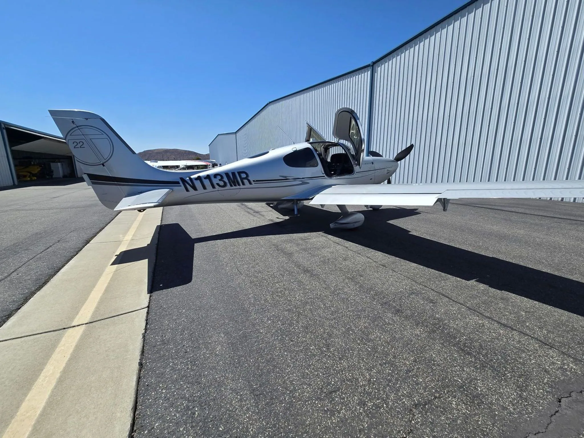


Free — save the SR22T to your watchlist and track it in one place.
More Cirrus SR22Tmanuals & documents
See all 21 →- Vantage 12 Pilot’s GuideV Speeds Reference
- Airworthiness Concern SheetAirworthiness Directives
- SERVICE BULLETIN HC-SB-30-390 Propeller - Spinner/Anti-ice Travel Tube InterferenceService Bulletins
- INSTRUCTIONS FOR INSTALLATION OF HARTZELL 4C1-F650A1/76C04(B)-0.6 PROPELLER ON CIRRUS SR22 AIRCRAFTMaintenance Manual
- INSTRUCTIONS FOR CONTINUED AIRWORTHINESS FOR HARTZELL 4C1-F650A1/76C04(B)-0.6 PROPELLER ON CIRRUS SR22T AIRCRAFTMaintenance Manual
- Supplemental Type Certificate SA03962ATSupplemental Type Certificate
- PILOT’S CHECKLIST SR22 G1 OR G2Checklist
- Continued Airworthiness Manual For Cirrus Design SR22 Series AirplanesMaintenance Manual
- Service Bulletin TAT SB10-01Service Bulletins
- Hartzell Engine Technologies Service Bulletin 033Service Bulletins
- SCHEDULE OF AIRWORTHINESS DIRECTIVESAirworthiness Directives
- Multi-Function Display Pilot’s GuidePerformance Data
If you fly the Cirrus SR22T, you may also be researching these.




In this document
General
This section introduces the aircraft and provides essential information for pilots and owners, including loading, fueling, and handling procedures. It also defines symbols and terminology used throughout the handbook.
Limitations
This section outlines the operational limitations of the Cirrus SR22, including weight limits, speed restrictions, and environmental conditions under which the aircraft can be safely operated.
Emergency Procedures
This section details the procedures to follow in various emergency situations, including engine failure, electrical failure, and other critical scenarios that may arise during flight.
Performance Data
This section provides performance specifications for the Cirrus SR22, including takeoff and landing distances, climb rates, and fuel consumption rates under various conditions.
Weight & Balance/Equipment List
This section includes information on the aircraft's weight limits, balance requirements, and a comprehensive list of equipment that may be installed on the aircraft.
Systems Description
This section describes the various systems of the Cirrus SR22, including the fuel system, electrical system, and avionics, providing pilots with a thorough understanding of the aircraft's capabilities.
Handling, Servicing & Maintenance
This section outlines the procedures for handling, servicing, and maintaining the aircraft to ensure its continued airworthiness and safety.
Safety Information
This section provides critical safety information and best practices for operating the Cirrus SR22, emphasizing the importance of adhering to the guidelines set forth in the POH.
Safety notes
- All limitations and procedures in this POH are mandatory for compliance with FAA operating rules.
- Failure to follow emergency procedures may result in loss of control or other serious consequences.
Full document text
P/N 13772-006 CoverPage-i PILOT’S OPERATING HANDBOOK AND FAA APPROVED AIRPLANE FLIGHT MANUAL for the CIRRUS SR22 A i r c r a f t S e r i a l s S R 2 2 - 4 4 3 3 & S u b s e q u e n t w i t h C i r r u s P e r s p e c t i v e + A v i o n i c s S y s t e m FAA Approved in Normal Category based on FAR 23. This document must be carried in the airplane at all times and be kept within the reach of the pilot during all flight operations. THIS HANDBOOK INCLUDES THE MATERIAL REQUIRED TO BE FURNISHED TO THE PILOT BY FAR PART 23 AND ADDITIONAL INFORMATION PROVIDED BY CIRRUS DESIGN AND CONSTITUTES THE FAA APPROVED AIRPLANE FLIGHT MANUAL. Model - Serial Num.: Registration Num.: Original Issue: December 28, 2016 CoverPage-ii P/N 13772-006 Copyright © 2016 - All Rights Reserved Cirrus Design Corporation 4515 Taylor Circle Duluth, MN 55811 Original Issue: December 28, 2016 Original Issue.......... ................... 28 Dec 2016 P/N 13772-006 A Cirrus Design Pilot’s Operating Handbook SR22 List of Effective Pages List of Effective Pages Use this page to determine the current effective date for each page in the POH. Supplements are issued individually and are controlled by the Log of Supplements Page in Section 9. Dates of original issue and revised pages are: Page Status Page Status Page Status Front Matter-1 Original Issue Front Matter-2 Original Issue Front Matter-3 Original Issue Front Matter-4 Original Issue Front Matter-5 Original Issue Front Matter-6 Original Issue 1-1 Original Issue 1-2 Original Issue 1-3 Original Issue 1-4 Original Issue 1-5 Original Issue 1-6 Original Issue 1-7 Original Issue 1-8 Original Issue 1-9 Original Issue 1-10 Original Issue 1-11 Original Issue 1-12 Original Issue 1-13 Original Issue 1-14 Original Issue 2-1 Original Issue 2-2 Original Issue 2-3 Original Issue 2-4 Original Issue 2-5 Original Issue 2-6 Original Issue 2-7 Original Issue 2-8 Original Issue 2-9 Original Issue 2-10 Original Issue 2-11 Original Issue 2-12 Original Issue 2-13 Original Issue 2-14 Original Issue 2-15 Original Issue 2-16 Original Issue 2-17 Original Issue 2-18 Original Issue 2-19 Original Issue 2-20 Original Issue 2-21 Original Issue 2-22 Original Issue 2-23 Original Issue 2-24 Original Issue 2-25 Original Issue 2-26 Original Issue 2-27 Original Issue 2-28 Original Issue 2-29 Original Issue 2-30 Original Issue 3-1 Original Issue 3-2 Original Issue 3-3 Original Issue 3-4 Original Issue 3-5 Original Issue 3-6 Original Issue 3-7 Original Issue 3-8 Original Issue 3-9 Original Issue 3-10 Original Issue 3-11 Original Issue 3-12 Original Issue 3-13 Original Issue 3-14 Original Issue 3-15 Original Issue 3-16 Original Issue 3-17 Original Issue 3-18 Original Issue 3-19 Original Issue 3-20 Original Issue 3-21 Original Issue 3-22 Original Issue 3-23 Original Issue 3-24 Original Issue 3-25 Original Issue 3-26 Original Issue 3-27 Original Issue 3-28 Original Issue 3-29 Original Issue 3-30 Original Issue 3-31 Original Issue 3-32 Original Issue 3-33 Original Issue 3-34 Original Issue 3-35 Original Issue 3-36 Original Issue 3A-1 Original Issue 3A-2 Original Issue 3A-3 Original Issue 3A-4 Original Issue 3A-5 Original Issue 3A-6 Original Issue 3A-7 Original Issue 3A-8 Original Issue 3A-9 Original Issue 3A-10 Original Issue 3A-11 Original Issue 3A-12 Original Issue 3A-13 Original Issue 3A-14 Original Issue 3A-15 Original Issue 3A-16 Original Issue 3A-17 Original Issue 3A-18 Original Issue 3A-19 Original Issue 3A-20 Original Issue 3A-21 Original Issue 3A-22 Original Issue 3A-23 Original Issue 3A-24 Original Issue 4-1 Original Issue Original Issue B P/N 13772-006 Cirrus Design Pilot’s Operating Handbook SR22 List of Effective Pages List of Effective Pages (Cont.) Page Status Page Status Page Status 4-2 Original Issue 4-3 Original Issue 4-4 Original Issue 4-5 Original Issue 4-6 Original Issue 4-7 Original Issue 4-8 Original Issue 4-9 Original Issue 4-10 Original Issue 4-11 Original Issue 4-12 Original Issue 4-13 Original Issue 4-14 Original Issue 4-15 Original Issue 4-16 Original Issue 4-17 Original Issue 4-18 Original Issue 4-19 Original Issue 4-20 Original Issue 4-21 Original Issue 4-22 Original Issue 4-23 Original Issue 4-24 Original Issue 4-25 Original Issue 4-26 Original Issue 4-27 Original Issue 4-28 Original Issue 4-29 Original Issue 4-30 Original Issue 5-1 Original Issue 5-2 Original Issue 5-3 Original Issue 5-4 Original Issue 5-5 Original Issue 5-6 Original Issue 5-7 Original Issue 5-8 Original Issue 5-9 Original Issue 5-10 Original Issue 5-11 Original Issue 5-12 Original Issue 5-13 Original Issue 5-14 Original Issue 5-15 Original Issue 5-16 Original Issue 5-17 Original Issue 5-18 Original Issue 5-19 Original Issue 5-20 Original Issue 5-21 Original Issue 5-22 Original Issue 5-23 Original Issue 5-24 Original Issue 5-25 Original Issue 5-26 Original Issue 5-27 Original Issue 5-28 Original Issue 5-29 Original Issue 5-30 Original Issue 5-31 Original Issue 5-32 Original Issue 6-1 Original Issue 6-2 Original Issue 6-3 Original Issue 6-4 Original Issue 6-5 Original Issue 6-6 Original Issue 6-7 Original Issue 6-8 Original Issue 6-9 Original Issue 6-10 Original Issue 7-1 Original Issue 7-2 Original Issue 7-3 Original Issue 7-4 Original Issue 7-5 Original Issue 7-6 Original Issue 7-7 Original Issue 7-8 Original Issue 7-9 Original Issue 7-10 Original Issue 7-11 Original Issue 7-12 Original Issue 7-13 Original Issue 7-14 Original Issue 7-15 Original Issue 7-16 Original Issue 7-17 Original Issue 7-18 Original Issue 7-19 Original Issue 7-20 Original Issue 7-21 Original Issue 7-22 Original Issue 7-23 Original Issue 7-24 Original Issue 7-25 Original Issue 7-26 Original Issue 7-27 Original Issue 7-28 Original Issue 7-29 Original Issue 7-30 Original Issue 7-31 Original Issue 7-32 Original Issue
Show full textShow less
7-33 Original Issue 7-34 Original Issue 7-35 Original Issue 7-36 Original Issue 7-37 Original Issue 7-38 Original Issue 7-39 Original Issue 7-40 Original Issue 7-41 Original Issue 7-42 Original Issue 7-43 Original Issue 7-44 Original Issue 7-45 Original Issue 7-46 Original Issue 7-47 Original Issue 7-48 Original Issue 7-49 Original Issue 7-50 Original Issue 7-51 Original Issue 7-52 Original Issue 7-53 Original Issue 7-54 Original Issue 7-55 Original Issue 7-56 Original Issue 7-57 Original Issue 7-58 Original Issue 7-59 Original Issue 7-60 Original Issue 7-61 Original Issue 7-62 Original Issue 7-63 Original Issue 7-64 Original Issue 7-65 Original Issue 7-66 Original Issue 7-67 Original Issue 7-68 Original Issue 7-69 Original Issue 7-70 Original Issue 7-71 Original Issue 7-72 Original Issue 7-73 Original Issue 7-74 Original Issue 7-75 Original Issue 7-76 Original Issue 7-77 Original Issue 7-78 Original Issue 7-79 Original Issue 7-80 Original Issue 7-81 Original Issue 7-82 Original Issue 7-83 Original Issue 7-84 Original Issue 7-85 Original Issue 7-86 Original Issue 7-87 Original Issue 7-88 Original Issue 7-89 Original Issue 7-90 Original Issue 7-91 Original Issue 7-92 Original Issue 7-93 Original Issue 7-94 Original Issue Original Issue P/N 13772-006 C Cirrus Design Pilot’s Operating Handbook SR22 List of Effective Pages List of Effective Pages (Cont.) Page Status Page Status Page Status 7-95 Original Issue 7-96 Original Issue 7-97 Original Issue 7-98 Original Issue 7-99 Original Issue 7-100 Original Issue 7-101 Original Issue 7-102 Original Issue 7-103 Original Issue 7-104 Original Issue 8-1 Original Issue 8-2 Original Issue 8-3 Original Issue 8-4 Original Issue 8-5 Original Issue 8-6 Original Issue 8-7 Original Issue 8-8 Original Issue 8-9 Original Issue 8-10 Original Issue 8-11 Original Issue 8-12 Original Issue 8-13 Original Issue 8-14 Original Issue 8-15 Original Issue 8-16 Original Issue 8-17 Original Issue 8-18 Original Issue 8-19 Original Issue 8-20 Original Issue 8-21 Original Issue 8-22 Original Issue 8-23 Original Issue 8-24 Original Issue 8-25 Original Issue 8-26 Original Issue 8-27 Original Issue 8-28 Original Issue 8-29 Original Issue 8-30 Original Issue 8-31 Original Issue 8-32 Original Issue 8-33 Original Issue 8-34 Original Issue 8-35 Original Issue 8-36 Original Issue 8-37 Original Issue 8-38 Original Issue 9-1 Original Issue 9-2 Original Issue 10-1 Original Issue 10-2 Original Issue 10-3 Original Issue 10-4 Original Issue 10-5 Original Issue 10-6 Original Issue 10-7 Original Issue 10-8 Original Issue 10-9 Original Issue 10-10 Original Issue 10-11 Original Issue 10-12 Original Issue Original Issue D P/N 13772-006 Cirrus Design Pilot’s Operating Handbook SR22 List of Effective Pages List of Effective Pages (Cont.) Page Status Page Status Page Status Original Issue Intentionally Left Blank Cirrus Design TPOH SR22 AFM Temporary Change TPOH 15-15R1 1 of 8 TPOH 15-15R1 1 of 8 SR22 Airplane Flight Manual (AFM) Temporary Change Information in this Temporary Change adds to, supersedes, or deletes information in the basic Pilot’s Operating Handbook. Affected Sections: • Section 7 - Systems Description • Section 8 - Handling and Servicing • Section 10 - Safety Information Affected Publications: SR22 Basic Airplane Flight Manuals: • PN 13772-006 Original / 13772-004 Rev 1 / 13772-002 Reissue A / 13772-001 Rev A10 (FAA Approved) • PN 13772-006AR Original / 13772-004AR Rev 1 / 13772-002AR Reissue A / 13772-001AR Rev A10 (FAA Approved on behalf of ANAC-DA of Argentina) • PN 13772-006E Original / 13772-004E Rev 1 / 13772-002E Rev 2 / 13772-001E Rev A10 (FAA Approved on behalf of EASA) • PN 21400-006 Original / 21400-004 Rev 1 / 21400-002 Rev 2 / 21400-001 Rev 6 (FAA Approved on behalf of ANAC of Brazil) Filing Instructions: Insert the following changes adjacent to the first page of each affected POH Section, and insert this TPOH cover page adjacent to the last page of the List of Effective Pages. Retain until further notice. Purpose: This POH Temporary Change updates information associated with the Brake System. TPOH was revised 14 May 2018 to add Affected Publications, expand SB2X-32-21 effectivity, and update Nose Wheel PSI. 14 May 2018 2 of 8 TPOH 15-15R1 TPOH Cirrus Design AFM Temporary Change SR22 14 May 2018 Intentionally Left Blank Cirrus Design TPOH SR22 AFM Temporary Change TPOH 17-02 1 of 2 TPOH 17-02 1 of 2 SR22 Airplane Flight Manual (AFM) Temporary Change Information in this Temporary Change adds to, supersedes, or deletes information in the basic Pilot’s Operating Handbook. Affected Sections: • Section 4 - Normal Procedures - Preflight Inspection, pages 4-4 thru 4-8.4 Affected Publications: SR22 Basic Airplane Flight Manuals: • PN 13772-006 Original Issue (FAA Approved) • PN 13772-006AR Original Issue (FAA Approved on behalf of ANAC-DA of Argentina) • PN 13772-006E Original Issue (FAA Approved on behalf of EASA) • PN 21400-006 Original Issue (FAA Approved on behalf of ANAC of Brazil) Filing Instructions: Insert the following revised pages and retain until further notice. Remove and discard the superseded pages. Insert this TPOH cover page adjacent to the last page of the List of Effective Pages and retain until further notice. Purpose: This POH Temporary Change revises the Preflight Inspection procedure. 27 Jul 2018 2 of 2 TPOH 17-02 TPOH Cirrus Design AFM Temporary Change SR22 27 Jul 2018 Intentionally Left Blank Cirrus Design TPOH SR22 AFM Temporary Change TPOH 17-04 1 of 2 TPOH 17-04 1 of 2 SR22 Airplane Flight Manual (AFM) Temporary Change Information in this Temporary Change adds to, supersedes, or deletes information in the basic Pilot’s Operating Handbook. Affected Sections: • Section 3 - Emergency Procedures - Table of Contents, pages 3-1 and 3-2 - Oxygen System Emergencies, pages 3-28.1 thru 3-28.2 • Section 3A - Abnormal Procedures - Table of Contents, pages 3A-1 and 3A-2 - Oxygen System, pages 3A-21 thru 3A-21.3 Affected Publications: SR22 Basic Airplane Flight Manuals: • PN 13772-006 Original Issue (FAA Approved) • PN 13772-006AR Original Issue (FAA Approved on behalf of ANAC-DA of Argentina) • PN 13772-006E Original Issue (FAA Approved on behalf of EASA) • PN 21400-006 Original Issue (FAA Approved on behalf of ANAC of Brazil) Filing Instructions: Insert the following revised pages and retain until further notice. Remove and discard the superseded pages. Insert this TPOH cover page adjacent to the last page of the List of Effective Pages and retain until further notice. Purpose: This POH Temporary Change adds the Oxygen System CAS Messages/Procedures. 11 May 2018 2 of 2 TPOH 17-04 TPOH Cirrus Design AFM Temporary Change SR22 11 May 2018 Intentionally Left Blank Cirrus Design TPOH SR22 AFM Temporary Change TPOH 17-08 1 of 2 TPOH 17-08 1 of 2 SR22 Airplane Flight Manual (AFM) Temporary Change Information in this Temporary Change adds to, supersedes, or deletes information in the basic Pilot’s Operating Handbook. Affected Sections: • Section 7 - Airplane and Systems Description - Pages 7-15 and 7-16 - Pages 7-93 and 7-94 Affected Publications: SR22 Basic Airplane Flight Manual: • PN 13772-006 Original Issue (FAA Approved) • PN 13772-006AR Original Issue (FAA Approved on behalf of ANAC-DA of Argentina) • PN 13772-006E Original Issue (FAA Approved on behalf of the European Aviation Safety Agency (EASA)) • PN 21400-006 Original Issue (FAA Approved on behalf of ANAC of Brazil) Filing Instructions: Insert the following revised pages and retain until further notice. Remove and discard the superseded pages. Insert this TPOH cover page adjacent to the last page of the List of Effective Pages and retain until further notice. Purpose: This POH Temporary Change revises the illustrations for Instrument Panel and Console, and Equipment Locations. 27 Jul 2018 2 of 2 TPOH 17-08 TPOH Cirrus Design AFM Temporary Change SR22 27 Jul 2018 Intentionally Left Blank Cirrus Design TPOH SR22 POH Temporary Change TPOH 17-10 1 of 2 TPOH 17-10 1 of 2 SR22 Pilot’s Operating Handbook (POH) Temporary Change Information in this Temporary Change adds to, supersedes, or deletes information in the basic Pilot’s Operating Handbook. Affected Sections: • Section 7 - Airplane and Systems Description - Pages 7-37 and 7-38 - Pages 7-49 and 7-50 - Pages 7-59 and 7-60 Affected Publications: SR22 Pilot’s Operating Handbook: • PN 13772-006 Original Issue (FAA Approved) • PN 13772-006AR Original Issue (FAA Approved on behalf of ANAC-DA of Argentina) • PN 13772-006E Original Issue (FAA Approved on behalf of the European Aviation Safety Agency (EASA)) • PN 21400-006 Original Issue (FAA Approved on behalf of ANAC of Brazil) Filing Instructions: Insert the following revised pages and retain until further notice. Remove and discard the superseded pages. Insert this TPOH cover page adjacent to the last page of the List of Effective Pages and retain until further notice. Purpose: This POH Temporary Change revises the illustrations for Fuel System Indication. Dec 22, 2017 2 of 2 TPOH 17-10 TPOH Cirrus Design POH Temporary Change SR22 Dec 22, 2017 Intentionally Left Blank Cirrus Design TPOH SR22 POH Temporary Change TPOH 18-06 1 of 2 TPOH 18-06 1 of 2 SR22 Pilot’s Operating Handbook (POH) Temporary Change Information in this Temporary Change adds to, supersedes, or deletes information in the basic Pilot’s Operating Handbook. Affected Sections: • Section 7 - Airplane and Systems Description - Pages 7-77 and 7-78 - Pages 7-83 and 7-84 Affected Publications: SR22 Pilot’s Operating Handbook: • PN 13772-006 Original (FAA Approved) • PN 13772-006AR Original (FAA Approved on behalf of ANAC-DA of Argentina) • PN 13772-006E Original (FAA Approved on behalf of EASA) • PN 21400-006 Original (FAA Approved on behalf of ANAC of Brazil) Filing Instructions: Insert the following revised pages and retain until further notice. Remove and discard the superseded pages. Insert this TPOH cover page adjacent to the last page of the List of Effective Pages and retain until further notice. Purpose: This POH Temporary Change adds model number updates for Engine Airframe Unit and Integrated Avionics Units, removes pairing information from Integrated Avionics Units description, and removes COM swap mode note from Audio Panel description. 11 May 2018 2 of 2 TPOH 18-06 TPOH Cirrus Design POH Temporary Change SR22 11 May 2018 Intentionally Left Blank Cirrus Design Front Matter SR22 Foreword P/N 13772-006 Front Matter-1 P/N 13772-006 Front Matter-1 Foreword This Pilot’s Operating Handbook (POH) has been prepared by Cirrus Design Corporation to familiarize operators with the aircraft. Read this POH carefully. It provides operational procedures that will assure the operator obtains the performance published in the manual, data designed to allow the most efficient use of the airplane, and basic information for maintaining the airplane in a “like new” condition. • Note • All limitations, procedures, maintenance & servicing requirements, and performance data contained in this POH are mandatory for compliance with FAA operating rules and for continued airworthiness of the airplane. This POH includes the material required to be furnished to the pilot by the Federal Aviation Regulations (FARs) and additional information provided by Cirrus Design Corporation and constitutes the FAA Approved Airplane Flight Manual for the aircraft. Original Issue Front Matter-2 P/N 13772-006 Front Matter Cirrus Design Foreword SR22 The Pilot’s Operating Handbook This Pilot’s Operating Handbook has been prepared using GAMA Specification #1 for Pilot’s Operating Handbook, Revision 2, dated 18 October 1996 as the content model and format guide. However, some deviations from this specification were made for clarity. The POH is presented in loose-leaf form for ease in inserting revisions and is sized for convenient storage. Tabbed dividers throughout the POH allow quick reference to each section. Logical and convenient Tables of Contents are located at the beginning of each section to aid in locating specific data within that section. The POH is divided into ten sections as follows: Section 1................................................................................... General Section 2...............................................................................Limitations Section 3.......................................................... Emergency Procedures Section 3A .......................................................... Abnormal Procedures Section 4.................................................................Normal Procedures Section 5................................................................... Performance Data Section 6...........................................Weight & Balance/Equipment List Section 7............................................................... Systems Description Section 8........................................Handling, Servicing & Maintenance Section 9........................................................................... Supplements Section 10.................................................................Safety Information The data presented in this POH is the result of extensive flight tests and is approved by the Federal Aviation Administration. However, as new procedures or performance data are developed, the POH will be revised. • Note • It is the responsibility of the owner to ensure that the Pilot’s Operating Handbook is current at all times. Therefore, it is very important that all revisions be properly incorporated into this POH as soon as they are available. Original Issue Cirrus Design Front Matter SR22 Foreword P/N 13772-006 Front Matter-3 P/N 13772-006 Front Matter-3 Revising the Pilot’s Operating Handbook Two types of revisions may be issued for this POH: Temporary and Numbered. Temporary revisions are printed on yellow paper, normally cover only one topic or procedure, and are issued to provide safety related information or other time sensitive information where the rigor of providing a numbered revision is not possible in the time allowed. All the information needed to properly file a temporary revision is included on the revision itself. Typically, a temporary revision is superseded and replaced by the next numbered revision. Numbered revisions are printed on white paper, normally cover several subjects, and are issued as general updates to the POH. Each numbered revision includes an “Instruction Sheet,” a “List of Effective Pages”, and a “Revision Highlights” page. The “Instruction Sheet” is intended to assist the manual holder in removing superseded pages and inserting new or superseding pages. The “List of Effective Pages” shows the issue or revision status of all pages in the POH. The “Revision Highlights” page gives a brief description of changes made to each page in the current revision. Identifying Revised Material Each page in the POH has revision identification at the lower inside corner opposite the page number. Original issue pages will be identified by the words “Original Issue” at this location. In the event that the majority of pages in the POH are revised, Cirrus may determine that it is more effective to reissue the POH. Reissued pages will be identified by the word “Reissue” followed by a letter indicating the reissue level; for example, “Reissue A” Revised pages will be identified by the word “Revision” followed by the revision number at this location; for example, “Revision 2” (Original Issue, Revision 2) or “Revision B1” (Reissue B, Revision 1). Revised material on a page can be identified by a change bar located at the outside page margin. Revision bars are not used at reissues of the POH. Original Issue Front Matter-4 P/N 13772-006 Front Matter Cirrus Design Foreword SR22 Revisions to the Pilot’s Operating Handbook POH revisions, temporary revisions, and supplements can be downloaded from Cirrus Design at www.cirrusaircraft.com, or from the Authorized Service Center website. Paper copies of POH revisions and supplements can be purchased from Cirrus Connection at www.cirrusconnection.com. • Note • If at any time it is found that the POH is not current, temporary revisions are missing, or applicable supplements are not included, contact Cirrus Design. Supplements The Supplements section (Section 9) of this POH contains FAA Approved Supplements necessary to safely and efficiently operate the airplane when equipped with optional equipment not provided with the standard airplane or not included in the POH. Supplements are essentially “mini-handbooks” and may contain data corresponding to most sections of the POH. Data in a supplement either adds to, supersedes, or replaces similar data in the basic POH. Section 9 includes a “Log of Supplements” page preceding all Cirrus Design Supplements produced for this airplane. The “Log of Supplements” page can be utilized as a “Table of Contents” for Section 9. If the airplane is modified at a non Cirrus Design facility through an STC or other approval method, it is the owner’s responsibility to ensure that the proper supplement, if applicable, is installed in the POH and that the supplement is properly recorded on the “Log of Supplements” page. FAA Approved POH Supplements must be in the airplane for flight operations when the subject optional equipment is installed or the special operations are to be performed. Retention of Data In the event a new title page is issued, the weight and balance data changes, the equipment list changes, or the “Log of Supplements” is replaced, the owner must ensure that all information applicable to the airplane is transferred to the new pages and the aircraft records are current. It is not a requirement that owners retain information, such as supplements, that is not applicable to their airplane. Original Issue Cirrus Design Front Matter SR22 Foreword P/N 13772-006 Front Matter-5 P/N 13772-006 Front Matter-5 In the event a new POH is purchased, the owner must ensure that all information applicable to the airplane is transferred to the new POH and the aircraft records are current. Warnings, Cautions, and Notes Warnings, Cautions, and Notes are used throughout this POH to focus attention on special conditions or procedures as follows: • WARNING • Warnings are used to call attention to operating procedures which, if not strictly observed, may result in personal injury or loss of life. • Caution • Cautions are used to call attention to operating procedures which, if not strictly observed, may result in damage to equipment. • Note • Notes are used to highlight specific operating conditions or steps of a procedure. Original Issue Front Matter-6 P/N 13772-006 Front Matter Cirrus Design Foreword SR22 Original Issue Intentionally Left Blank P/N 13772-006 1-1 Cirrus Design Section 1 SR22 General Introduction ........................................................................................ 3 The Airplane....................................................................................... 7 Engine............................................................................................. 7 Propeller ......................................................................................... 7 Fuel................................................................................................. 8 Oil .................................................................................................. 8 Maximum Certificated Weights ....................................................... 8 Cabin and Entry Dimensions .......................................................... 8 Baggage Spaces and Entry Dimensions ........................................ 8 Specific Loadings............................................................................ 8 Symbols, Abbreviations and Terminology.......................................... 9 General Airspeed Terminology and Symbols ................................. 9 Meteorological Terminology.......................................................... 10 Engine Power Terminology........................................................... 11 Performance and Flight Planning Terminology............................. 11 Weight and Balance Terminology................................................. 12 Original Issue Section 1: General Table of Contents 1-2 P/N 13772-006 Section 1 Cirrus Design General SR22 Original Issue Intentionally Left Blank Cirrus Design Section 1 SR22 General P/N 13772-006 1-3 P/N 13772-006 1-3 Introduction This section contains information of general interest to pilots and owners. You will find the information useful in acquainting yourself with the airplane, as well as in loading, fueling, sheltering, and handling the airplane during ground operations. Additionally, this section contains definitions or explanations of symbols, abbreviations, and terminology used throughout this handbook. • Note • For specific information regarding the organization of this Handbook, revisions, supplements, and procedures to be used to obtain publications, see the “Foreword” section. All liquid volumes referenced in this publication are expressed in United States Customary Units, e.g., U.S. Gallons. Original Issue 1-4 P/N 13772-006 Section 1 Cirrus Design General SR22 Figure 1-1 Airplane Three View 78 inches 3-BLADE 198 cm 38.3 ft 11.67 m 9.1 ft 2.8 m 9 inches (minimum) 23 cm (minimum) 26.0 ft 7.92 m 8.9 ft 2.71 m NOTE: • Wing span includes position and strobe lights. • Prop ground clearance - 9" inches (23 cm). • Wing Area = 144.9 sq. ft. SR22_FM01_5313 Original Issue Cirrus Design Section 1 SR22 General P/N 13772-006 1-5 P/N 13772-006 1-5 Location Length Width Height Volume Cabin 122” 49.3” 49.7 137 cu ft Baggage Compartment 36” 39.8” 38.5” 32 cu ft Figure 1-2 Airplane Interior Dimensions 39.8" 49.3" 240 220 200 180 160 140 120 16.0" 49.7" 27.0" 38.5" FS 10.5" 33.4" 39.0" 20.0" 33.3" 32.0" SR22_FM01_5315 100 222 CABIN DOOR OPENING BAGGAGE DOOR OPENING 20.0" 21.0" 5.0" Station Fuselage Original Issue 1-6 P/N 13772-006 Section 1 Cirrus Design General SR22 Figure 1-3 Turning Radius 9.1 ft. (2.77 m) 0.5 ft. (0.15 m) 24.3 ft. (7.41 m) 7.0 ft. (2.16 m) RADIUS FOR NOSE GEAR RADIUS FOR OUTSIDE GEAR RADIUS FOR INSIDE GEAR RADIUS FOR WING TIP TURNING RADII ARE CALCULATED USING ONE BRAKE AND PARTIAL POWER. ACTUAL TURNING RADIUS MAY VARY AS MUCH AS THREE FEET. GROUND TURNING CLEARANCE SR22_FM01_5399 Original Issue Cirrus Design Section 1 SR22 General P/N 13772-006 1-7 P/N 13772-006 1-7 The Airplane Engine Number of Engines.............................................................................. 1 Number of Cylinders............................................................................ 6 Engine Manufacturer ............................................Teledyne Continental Engine Model ......................................................................... IO-550-N Fuel Metering ................................................................... Fuel Injected Engine Cooling ..................................................................... Air Cooled Engine Type.................................... Horizontally Opposed, Direct Drive Horsepower Rating................................................ 310 hp @ 2700 rpm Propeller Hartzell Propeller Type ........................................Constant Speed, Three Blade Model Number.............................................. PHC-J3YF-1RF/F7694(B) Diameter.............................................................78.0” (76.0” Minimum) Model Number......................................... PHC-J3YF-1RF/F7693DF(B) Diameter.............................................................78.0" (76.0" Minimum) or McCauley Propeller Type ........................................Constant Speed, Three Blade Model Number.................................................... D3A34C443/78CYA-0 Diameter.............................................................78.0" (76.0" Minimum) or MT Propeller Propeller Type ........................................Constant Speed, Three Blade Model Number.............................................................MTV-9-D/198-52 Diameter.............................................................78.0" (76.0" Minimum) Original Issue 1-8 P/N 13772-006 Section 1 Cirrus Design General SR22 Fuel Total Capacity .............................................94.5 U.S. Gallons (358.0 L) Total Usable................................................92.0 U.S. Gallons (348.0 L) Approved Fuel Grades: 100 LL Grade Aviation Fuel (Blue) 100 (Formerly 100/130) Grade Aviation Fuel (Green) Oil Oil Capacity (Sump) .............................................8 U.S. Quarts (7.6 L) Oil Grades: All Temperatures ............................. SAE 15W-50, 20W-50, or 20W-60 Below 40°F (4°C).......................................................................SAE 30 Above 40°F (4°C) ......................................................................SAE 50 Maximum Certificated Weights Maximum Gross for Takeoff...................................... 3600 lb (1633 Kg) Maximum Zero Fuel Weight...................................... 3400 lb (1542 Kg) Maximum Baggage Compartment Loading .................... 130 lb (59 Kg) Cabin and Entry Dimensions Refer to the preceding figures for dimensions of the cabin interior and entry door openings. Baggage Spaces and Entry Dimensions Refer to the preceding figures for dimensions of the baggage area and baggage door opening. Specific Loadings Wing Loading..................................................... 24.8 lb per square foot Power Loading................................................................. 11.4 lb per hp Original Issue Cirrus Design Section 1 SR22 General P/N 13772-006 1-9 P/N 13772-006 1-9 Symbols, Abbreviations and Terminology General Airspeed Terminology and Symbols KCAS Knots Calibrated Airspeed is the indicated airspeed corrected for position and instrument error. Calibrated airspeed is equal to true airspeed in standard atmosphere at sea level. KIAS Knots Indicated Airspeed is the speed shown on the airspeed indicator. The IAS values published in this handbook assume no instrument error. KTAS Knots True Airspeed is the airspeed expressed in knots relative to undisturbed air which is KCAS corrected for altitude and temperature. VG Best Glide Speed is the speed at which the greatest flight distance is attained per unit of altitude lost with power off. VO Operating Maneuvering Speed is the maximum speed at which application of full control movement will not overstress the airplane. V FE Maximum Flap Extended Speed is the highest speed permissible with wing flaps in a prescribed extended position. V NO Maximum Structural Cruising Speed is the speed that should not be exceeded except in smooth air, and then only with caution. V NE Never Exceed Speed is the speed that may not be exceeded at any time. V PD Maximum Demonstrated Parachute Deployment Speed is the maximum speed at which parachute deployment has been demonstrated. V REF Landing reference speed or threshold crossing speed. V S Stalling Speed is minimum steady flight speed at which the aircraft is controllable. Original Issue 1-10 P/N 13772-006 Section 1 Cirrus Design General SR22 Meteorological Terminology V S 50% Stalling Speed is minimum steady flight speed at which the aircraft is controllable with 50% flaps. V SO Stalling Speed is the minimum steady flight speed at which the aircraft is controllable in the landing configuration (100% flaps) at the most unfavorable weight and balance. V X Best Angle of Climb Speed is the speed at which the airplane will obtain the highest altitude in a given horizontal distance. The best angle-of-climb speed normally increases slightly with altitude. V Y Best Rate of Climb Speed is the speed at which the airplane will obtain the maximum increase in altitude per unit of time. The best rate-of-climb speed decreases slightly with altitude. IMC Instrument Meteorological Conditions are meteorological conditions expressed in terms of visibility, distance from cloud, and ceiling less than the minima for visual flight defined in FAR 91.155. ISA International Standard Atmosphere (standard day) is an atmosphere where (1) the air is a dry perfect gas, (2) the temperature at sea level is 15°C, (3) the pressure at sea level is 29.92 in.Hg (1013.2 millibars), and (4) the temperature gradient from sea level to the altitude at which the temperature is - 56.5°C is -0.00198°C per foot and zero above that altitude. MSL Mean Sea Level is the average height of the surface of the sea for all stages of tide. In this Handbook, altitude given as MSL is the altitude above the mean sea level. It is the altitude read from the altimeter when the altimeter’s barometric adjustment has been set to the altimeter setting obtained from ground meteorological sources. Original Issue Cirrus Design Section 1 SR22 General P/N 13772-006 1-11 P/N 13772-006 1-11 Engine Power Terminology Performance and Flight Planning Terminology OAT Outside Air Temperature is the free air static temperature obtained from inflight temperature indications or from ground meteorological sources. It is expressed in either degrees Celsius or degrees Fahrenheit. Pressure Altitude Pressure Altitude is the altitude read from the altimeter when the altimeter’s barometric adjustment has been set to 29.92 in.Hg (1013 mb) corrected for position and instrument error. In this Handbook, altimeter instrument errors are assumed to be zero. Standard Temperature Standard Temperature is the temperature that would be found at a given pressure altitude in the standard atmosphere. It is 15°C (59°F) at sea level pressure altitude and decreases approximately 2°C (3.6°F) for each 1000 feet of altitude increase. See ISA definition. HP Horsepower is the power developed by the engine. MCP Maximum Continuous Power is the maximum power that can be used continuously. MAP Manifold Pressure is the pressure measured in the engine’s induction system expressed as in. Hg. RPM Revolutions Per Minute is engine rotational speed. Static RPM Static RPM is RPM attained during a full-throttle engine runup when the airplane is on the ground and stationary. g One “g” is a quantity of acceleration equal to that of earth’s gravity. Original Issue 1-12 P/N 13772-006 Section 1 Cirrus Design General SR22 Weight and Balance Terminology Demonstrated Crosswind Velocity Demonstrated Crosswind Velocity is the velocity of the crosswind component for which adequate control of the airplane during taxi, takeoff, and landing was actually demonstrated during certification testing. Demonstrated crosswind is not considered to be limiting. Service Ceiling Service Ceiling is the maximum altitude at which the aircraft at maximum weight has the capability of climbing at a rate of 100 feet per minute. GPH Gallons Per Hour is the amount of fuel (in gallons) consumed by the aircraft per hour. NMPG Nautical Miles Per Gallon is the distance (in nautical miles) which can be expected per gallon of fuel consumed at a specific engine power setting and/or flight configuration. Unusable Fuel Unusable Fuel is the quantity of fuel that cannot be safely used in flight. Usable Fuel Usable Fuel is the fuel available for flight planning. CG Center of Gravity is the point at which an airplane would balance if suspended. Its distance from the reference datum is found by dividing the total moment by the total weight of the airplane. Arm Arm is the horizontal distance from the reference datum to the center of gravity (CG) of an item. The airplane’s arm is obtained by adding the airplane’s individual moments and dividing the sum by the total weight. Moment Moment is the product of the weight of an item multiplied by its arm. Standard Empty Weight Standard Empty Weight is the weight of a standard airplane including unusable fuel, full operating fluids, and full oil Original Issue Cirrus Design Section 1 SR22 General P/N 13772-006 1-13 P/N 13772-006 1-13 Basic Empty Weight Basic Empty Weight is the actual weight of the airplane including all operating equipment that has a fixed location in the airplane. The basic empty weight includes the weight of unusable fuel and full oil. MAC Mean Aerodynamic Chord is the chord drawn through the centroid of the wing plan area. LEMAC Leading Edge of Mean Aerodynamic Chord is the forward edge of MAC given in inches aft of the reference datum (fuselage station). Maximum Gross Weight Maximum Gross Weight is the maximum permissible weight of the airplane and its contents as listed in the aircraft specifications. Maximum Zero Fuel Weight Maximum Zero Fuel Weight is the maximum permissible weight of the airplane and its contents minus the total weight of the fuel onboard. Useful Load Useful Load is the basic empty weight subtracted from the maximum weight of the aircraft. It is the maximum allowable combined weight of pilot, passengers, fuel and baggage. Station Station is a location along the airplane fuselage measured in inches from the reference datum and expressed as a number. For example: A point 123 inches aft of the reference datum is Fuselage Station 123.0 (FS 123). Reference Datum Reference Datum is an imaginary vertical plane from which all horizontal distances are measured for balance purposes. Tare Tare is the weight of all items used to hold or position the airplane on the scales for weighing. Tare includes blocks, shims, and chocks. Tare weight must be subtracted from the associated scale reading. Original Issue 1-14 P/N 13772-006 Section 1 Cirrus Design General SR22 Original Issue Intentionally Left Blank P/N 13772-006 2-1 Cirrus Design Section 2 SR22 Limitations Introduction ........................................................................................ 3 Certification Status ............................................................................. 3 Airspeed Limitations........................................................................... 4 Airspeed Indicator Markings .............................................................. 5 Powerplant Limitations ....................................................................... 6 Engine............................................................................................. 6 Propeller ......................................................................................... 7 Weight Limits ..................................................................................... 7 Engine Instrument Markings & Annunciations ................................... 8 PowerPlant ..................................................................................... 8 Fuel................................................................................................. 9 Electrical ......................................................................................... 9 Center of Gravity Limits ................................................................... 10 Maneuver Limits............................................................................... 11 Flight Load Factor Limits.................................................................. 11 Minimum Flight Crew ....................................................................... 11 Kinds of Operation ........................................................................... 12 Kinds of Operation Equipment List ............................................... 12 Icing .............................................................................................. 16 Runway Surface ........................................................................... 16 Taxi Power.................................................................................... 16 Fuel Limits........................................................................................ 17 Altitude Limits................................................................................... 17 Environmental Conditions ................................................................ 17 Maximum Occupancy ...................................................................... 18 Refer to Section 7, Seats for additional information......................... 18 Systems and Equipment Limits........................................................ 19 Cirrus Perspective+ Integrated Avionics System.......................... 19 L-3 Stormscope Weather Information System (optional).............. 22 Max Viz Enhanced Vision System (Optional) ............................... 23 MD302 Standby Attitude Module (Optional) ................................. 23 Air Conditioning System (Optional)............................................... 23 Inflatable Restraint System........................................................... 23 Flap Limitations............................................................................. 23 Paint.............................................................................................. 24 Cirrus Airframe Parachute System (CAPS) .................................. 24 Original Issue Section 2: Limitations Table of Contents 2-2 P/N 13772-006 Section 2 Cirrus Design Limitations SR22 Other Limitations .............................................................................. 24 Smoking ........................................................................................ 24 Placards ........................................................................................... 25 Original Issue Cirrus Design Section 2 SR22 Limitations P/N 13772-006 2-3 P/N 13772-006 2-3 Introduction The limitations included in this Section of the Pilot’s Operating Handbook (POH) are approved by the Federal Aviation Administration. This section provides operating limitations, instrument markings and basic placards required by regulation and necessary for the safe operation of the aircraft and its standard systems and equipment. Refer to Section 9: Log of Supplements of this handbook for amended operating limitations for airplanes equipped with optional equipment. Compliance with the operating limitations in this section and in Section 9 is required by Federal Aviation Regulations. • Note • Limitations associated with optional equipment are not described in this section. For optional equipment limitations, refer to Section 9: Log of Supplements. Certification Status The aircraft is certificated under the requirements of Federal Aviation Regulations (FAR) Part 23 as documented by FAA Type Certificate TC A00009CH. Original Issue 2-4 P/N 13772-006 Section 2 Cirrus Design Limitations SR22 Airspeed Limitations The indicated airspeeds in the following table are based on Section 5, Airspeed Calibration - Normal Static Source Table. When using the alternate static source, allow for the airspeed calibration variations between the normal and alternate static sources. Speed KIAS KCAS Remarks VNE 205 208 Never Exceed Speed is the speed limit that may not be exceeded at any time. VNO 176 179 Maximum Structural Cruising Speed is the speed that should not be exceeded except in smooth air, and then only with caution. VO 3600 Lb 140 142 Operating Maneuvering Speed is the maxi- mum speed at which full control travel may be used. Below this speed the airplane stalls before limit loads are reached. Above this speed, full control movements can damage the airplane. VFE 50% Flaps 100% Flaps 150 110 152 111 Maximum Flap Extended Speed is the highest speed permissible with wing flaps extended. VPD 140 142 Maximum Demonstrated Parachute Deploy- ment Speed is the maximum speed at which parachute deployment has been demon- strated. Original Issue Cirrus Design Section 2 SR22 Limitations P/N 13772-006 2-5 P/N 13772-006 2-5 Airspeed Indicator Markings The airspeed indicator markings are based on Section 5, Airspeed Calibration - Normal Static Source Table. When using the alternate static source, allow for the airspeed calibration variations between the normal and alternate static sources. Marking Value (KIAS) Remarks White Arc 64 - 110 Full Flap Operating Range. Lower limit is the most adverse stall speed in the landing configuration. Upper limit is the maximum speed permissible with flaps extended. Green Arc 74 - 176 Normal Operating Range. Lower limit is the maximum weight stall at most forward CG with flaps retracted. Upper limit is the maximum structural cruising speed. Yellow Arc 176 - 205 Caution Range. Operations must be conducted with caution and only in smooth air. Red Line 205 Never exceed speed. Maximum speed for all opera- tions. Original Issue 2-6 P/N 13772-006 Section 2 Cirrus Design Limitations SR22 Powerplant Limitations Engine Teledyne Continental .............................................................. IO-550-N Power Rating ....................................................... 310 hp @ 2700 RPM Maximum RPM ..................................................................... 2700 RPM Oil Temperature ........................................... 240 °F (116 °C) maximum Minimum Oil Temperature for Takeoff ............................... 75 °F (24 °C) Oil Pressure: Minimum................................................................................ 10 psi Maximum............................................................................. 100 psi Approved Oils: Engine Break-In: For first 25 hours of operation or until oil consumption stabilizes use straight mineral oil conforming to MIL- L-6082. If engine oil must be added to the factory installed oil, add only MIL-L-6082 straight mineral oil. After Engine Break-In: Use only oils conforming to Teledyne Continental Specification MHS-24 (Ashless Dispersant Lubrication Oil) or MHS-25 (Synthetic Lubrication Oil). Refer to Section 8, Approved Oils. All Temperatures ............................... 15W-50, 20W-50 or 20W-60 Above 40 °F (4 °C) ...............................SAE 50, 20W50, or 20W60 Below 40 °F (4 °C) ................. SAE 30, 10W30, 15W50, or 20W50 Fuel Grade....................... Aviation Grade 100 LL (Blue) or 100 (green) • Note • Refer to Fuel Limits in this Section for operational limitations regarding fuel and fuel storage. Original Issue Cirrus Design Section 2 SR22 Limitations P/N 13772-006 2-7 P/N 13772-006 2-7 Propeller Hartzell Propeller Type ........................................Constant Speed, Three Blade Model Number.............................................. PHC-J3YF-1RF/F7694(B) Diameter.............................................................78.0” (76.0” Minimum) Model Number......................................... PHC-J3YF-1RF/F7693DF(B) Diameter.............................................................78.0" (76.0" Minimum) or McCauley Propeller Type ........................................Constant Speed, Three Blade Model Number.................................................... D3A34C443/78CYA-0 Diameter.............................................................78.0" (76.0" Minimum) or MT Propeller Propeller Type ........................................Constant Speed, Three Blade Model Number.............................................................MTV-9-D/198-52 Diameter.............................................................78.0" (76.0" Minimum) Weight Limits Maximum Takeoff Weight ......................................... 3600 lb (1633 Kg) Maximum Weight in Baggage Compartment.................. 130 lb (59 Kg) Maximum Zero Fuel Weight ..................................... 3400 lb (1542 Kg) Original Issue 2-8 P/N 13772-006 Section 2 Cirrus Design Limitations SR22 Engine Instrument Markings & Annunciations The following describes the engine instrument markings. Associated Warning and Caution Annunciations are shown in capitalized text. PowerPlant *Engine Speed Warning when RPM between 2710 and 2730 for more than 10 seconds OR when RPM greater than 2730 for more than 5 seconds. **Oil Pressure Caution when oil pressure is between 10 and 29 psi and RPM is greater than 1000. Oil Pressure Warning when oil pressure is below 10 psi, OR oil pressure is above 100 psi. Instrument (Range & Units) Red Arc/Bar Yellow Arc/Bar Green Arc/ Bar Yellow Arc/ Bar Red Arc/Bar Lower Warning Range Minimum Caution Range Normal Range Maximum Caution Range Upper Warning Range Cylinder Head Temperature (100°F – 500°F) –– –– 240 – 420 420 – 460 CHT > 460 CHT Engine Speed (0 – 3000 RPM) –– –– 500 – 2700 –– > 2700* RPM Exhaust Gas Temperature (1000°F – 1600°F) –– –– 1000–1600 –– –– Manifold Pressure (10 – 35 Inch Hg) –– –– 15 – 29.5 –– –– Oil Pressure (0 – 100 PSI) 0 – 10** OIL PRESS 10 – 30** OIL PRESS 30 – 60 60 – 100 > 100** OIL PRESS Oil Temperature (75°F – 250°F) –– –– 100 – 240 > 240 OIL TEMP Percent Power (0 – 100%) –– –– 0 – 100 –– –– Original Issue Cirrus Design Section 2 SR22 Limitations P/N 13772-006 2-9 P/N 13772-006 2-9 Fuel a Top of green arc dynamically changes based on altitude. Electrical d 20 second delay. e 30 second delay. Instrument (Range & Units) Red Arc/Bar Yellow Arc/Bar Green Arc/Bar Yellow Arc/Bar Red Arc/Bar Minimum Minimum Caution Range Normal Range Maximum Caution Range Maximum Fuel Flow (0 – 30 U.S. Gal/Hr) –– –– 0 – 25a –– –– Fuel Totalizer (U.S. Gallon) N < 9 FUEL QTY 9 – 18 > 18 –– –– Fuel Quantity Gage (0 – 46 U.S. Gallon) 0 10 – 14 14 – 46 –– –– Instrument (Range & Units) Red Arc/Bar Yellow Arc/Bar Green Arc/Bar Yellow Arc/Bar Red Arc/Bar Minimum Minimum Caution Range Normal Range Maximum Caution Range Maximum Essential Bus Volts (0 – 36 Volts) 0 – 24.4 ESS BUS –– 24.5 – 32 –– > 32 ESS BUS Main Bus 1 Voltage (0 – 36 Volts) –– 0 – 24.4 M BUS 1 M BUS 1 24.5 – 32 –– > 32 M BUS 1 Main Bus 2 Voltage (0 – 36 Volts) –– 0 – 24.4 M BUS 2 24.5 – 32 –– > 32 M BUS 2 Alternator 1 Current (0 – 100 Amps) –– –– 2 – 100 0 – 1 d ALT 1 –– Alternator 2 Current (0 – 70 Amps) –– –– 2 – 100 0 – 1 d ALT 2 –– Battery 1 Current (-59 to 59 Amps) –– –– -4 – 59 -59 to -5 e BATT 1 –– Original Issue 2-10 P/N 13772-006 Section 2 Cirrus Design Limitations SR22 Center of Gravity Limits Reference Datum ....................................100 inches forward of firewall Forward....................................................................Refer to Figure 2-1 Aft ............................................................................Refer to Figure 2-1 Figure 2-1 CG Envelope FORWARD LIMIT - The forward limit is FS 137.8 (9.8% MAC) at 2100 lb, with straight line taper to FS 139.1 (12.5% MAC) at 2700 lb, to FS 143.2 (21.1% MAC) at 3600 lb. AFT LIMIT - The aft limit is FS 148.2 (31.5% MAC) at all weights from 2100 lb to 3600 lb. 2000 2200 2400 2600 2800 3000 3200 3400 3600 C.G. - Inches Aft of Datum Weight - Pounds 12.5% MAC FS 139.1 2700 lb 9.8% MAC FS 137.8 2100 lb 31.5% MAC FS 148.2 2100 lb 21.1% MAC FS 143.2 3600 lb 31.5% MAC FS 148.2 3600 lb Max Zero Fuel 138 136 140 142 144 146 148 150 SR22_FM02_5317 Original Issue Cirrus Design Section 2 SR22 Limitations P/N 13772-006 2-11 P/N 13772-006 2-11 Maneuver Limits Aerobatic maneuvers are prohibited. Spins are prohibited. This airplane is certified in the normal category and is not designed for aerobatic operations. Only those operations incidental to normal flight are approved. These operations include normal stalls, chandelles, lazy eights, and turns in which the angle of bank is limited to 60°. • Note • Because the aircraft has not been certified for spin recovery, the Cirrus Airframe Parachute System (CAPS) must be deployed if the airplane departs controlled flight. Refer to Section 3, Inadvertent Spin Entry. Flight Load Factor Limits Flaps UP (0%), 3600 lb. .....................................................+3.8g, -1.9g Flaps 50%, 3600 lb................................................................. +1.9g, 0g Flaps 100%, 3600 lb............................................................... +1.9g, 0g Minimum Flight Crew The minimum flight crew is one pilot. Original Issue 2-12 P/N 13772-006 Section 2 Cirrus Design Limitations SR22 Kinds of Operation The aircraft is equipped and approved for the following type operations: • VFR day and night. • IFR day and night. Kinds of Operation Equipment List The following listing summarizes the equipment required under Federal Aviation Regulations (FAR) Part 23 for airworthiness under the listed kind of operation. Those minimum items of equipment necessary under the operating rules are defined in FAR Part 91 and FAR Part 135 as applicable. • Note • All references to types of flight operations on the operating limitations placards are based upon equipment installed at the time of Airworthiness Certificate issuance. System, Instrument, and/ or Equipment Kinds of Operation Remarks, Notes, and/or Exceptions VFR Day VFR Nt. IFR Day IFR Nt. Placards and Markings Airplane Flight Manual (Included w/ POH) 1 1 1 1 Communications VHF COM — — 1 1 Electrical Power Battery 1 1 1 1 1 Battery 2 — — 1 1 Alternator 1 1 1 1 1 Alternator 2 — — 1 1 Amp Meter/Indication 1 1 1 1 Original Issue Cirrus Design Section 2 SR22 Limitations P/N 13772-006 2-13 P/N 13772-006 2-13 Low Volts Annunciator 1 1 1 1 ALT 1 Annunciator 1 1 1 1 ALT 2 Annunciator — — 1 1 Circuit Breakers A/R A/R A/R A/R As required. Equipment & Furnishings Emergency Locator Trans- mitter 1 1 1 1 Restraint System A/R A/R A/R A/R One seat belt for each occupant. Fire Protection Fire Extinguisher 1 1 1 1 Flight Controls Flap Position Indicator 1 1 1 1 Flap System 1 1 1 1 Pitch Trim Indicator 1 1 1 1 Pitch Trim System 1 1 1 1 Roll Trim Indicator 1 1 1 1 Roll Trim System 1 1 1 1 Stall Warning System 1 1 1 1 Fuel Auxiliary Fuel Pump 1 1 1 1 Fuel Quantity Indicators 2 2 2 2 Fuel Selector Valve 1 1 1 1 System, Instrument, and/ or Equipment Kinds of Operation (Continued) Remarks, Notes, and/or Exceptions VFR Day VFR Nt. IFR Day IFR Nt. Original Issue 2-14 P/N 13772-006 Section 2 Cirrus Design Limitations SR22 Ice & Rain Protection Alternate Engine Air Induc- tion System 1 1 1 1 Alternate Static Air Source 1 1 1 1 Pitot Heater — — 1 1 Landing Gear Wheel Pants — — — — May be removed. Lights PFD Bezel Lighting — — — 1 PFD Backlighting * 1 1 1 *Required if MFD Backlighting Fails. Engine Indicators Must Be Shown in Backup Mode. MFD Bezel Lighting — — — 1 MFD Backlighting * 1 1 1 *Required if PFD Backlighting Fails. Engine Indicators Must Be Shown in Backup Mode. Anticollision Lights 2 2 2 2 Instrument Lights — 1 — 1 Navigation Lights — 2 — 2 Landing Light — 1 — 1 For hire operations. Flash Light — 1 — 1 System, Instrument, and/ or Equipment Kinds of Operation (Continued) Remarks, Notes, and/or Exceptions VFR Day VFR Nt. IFR Day IFR Nt. Original Issue Cirrus Design Section 2 SR22 Limitations P/N 13772-006 2-15 P/N 13772-006 2-15 Navigation & Pitot Static Airspeed Indicator 1 1 1 1 Altimeter 1 1 1 1 Magnetic Compass 1 1 1 1 Pitot System 1 1 1 1 Static System, Normal 1 1 1 1 Attitude Indicator — — 1 1 Clock — — 1 1 Gyroscopic Directional Indi- cation (HSI) — — 1 1 Magnetometer — — 1 1 Nav Radio — — 1 1 PFD Airspeed Indication — — 1 1 PFD Altitude Indication — — 1 1 PFD Attitude Indication — — 1 1 PFD Heading Indication — — 1 1 PFD Slip/Skid Indication — — 1 1 Turn Coordinator — — 1 1 Altitude Encoder A/R A/R 1 1 As required per procedure. GPS Receiver/Navigator — — A/R A/R As required per procedure. Marker Beacon Receiver — — A/R A/R As required per procedure. VHF Navigation Radio — — A/R A/R As required per procedure. System, Instrument, and/ or Equipment Kinds of Operation (Continued) Remarks, Notes, and/or Exceptions VFR Day VFR Nt. IFR Day IFR Nt. Original Issue 2-16 P/N 13772-006 Section 2 Cirrus Design Limitations SR22 Icing Flight into known icing conditions is prohibited. Runway Surface This airplane may be operated on any smooth runway surface. Taxi Power Maximum continuous engine speed for taxiing is 1000 RPM on flat, smooth, hard surfaces. Power settings slightly above 1000 RPM are permissible to start motion, for turf, soft surfaces, and on inclines. Use minimum power to maintain taxi speed. Vertical Speed Indicator — — — — Engine Indicating Cylinder Head Temperature Indication — — — — Exhaust Gas Temperature Indication — — — — Fuel Flow Indication 1 1 1 1 Manifold Pressure Indica- tion 1 1 1 1 Oil Pressure Indication 1 1 1 1 Oil Quantity Indicator (Dip- stick) 1 1 1 1 Oil Temperature Indication 1 1 1 1 Engine Speed 1 1 1 1 Special Equipment Cirrus Airframe Parachute (CAPS) 1 1 1 1 System, Instrument, and/ or Equipment Kinds of Operation (Continued) Remarks, Notes, and/or Exceptions VFR Day VFR Nt. IFR Day IFR Nt. Original Issue Cirrus Design Section 2 SR22 Limitations P/N 13772-006 2-17 P/N 13772-006 2-17 Fuel Limits Approved Fuel ............... Aviation Grade 100 LL (Blue) or 100 (Green) Total Fuel Capacity...................................... 94.5 U.S. Gallon (358.0 L) Total Fuel Each Tank ................................. 47.25 U.S. Gallon (179.0 L) Total Usable Fuel (all flight conditions) ........ 92.0 U.S. Gallon (348.0 L) Maximum Allowable Fuel Imbalance ............. 10.0 U.S. Gallon (37.9 L) The fuel pump must be set to BOOST for takeoff, climb, landing, and for switching fuel tanks. Altitude Limits Maximum Takeoff Altitude ..........................................10,000 Feet MSL Maximum Operating Altitude ......................................17,500 Feet MSL The operating rules (FAR Part 91 and FAR Part 135) require the use of supplemental oxygen at specified altitudes below the maximum operating altitude. Environmental Conditions For operation of the airplane below an outside air temperature of -10°F (-23°C), use of cowl inlet covers approved by Cirrus Design and listed in the Winterization Kit AFM Supplement P/N 13772-118 is required. Original Issue 2-18 P/N 13772-006 Section 2 Cirrus Design Limitations SR22 Maximum Occupancy Occupancy of this airplane is limited to “4+1” persons, the pilot and four passengers. If carrying three rear seat passengers, occupants must be wearing a seat belt and shoulder harness with their hips and back firmly against the seatback as shown in the following illustration. If three rear seat passengers cannot meet these requirements, occupancy is limited to four persons. Child Restraint System 1. Rear seat configuration for LATCH / ISOFIX compliant child seats is limited to two seats in the outboard positions. 2. A single non-LATCH / ISOFIX compliant seat may be installed in the center seat position. 3. Installation of three child seats in the rear seat is prohibited. Refer to Section 7, Seats for additional information. Figure 2-2 Rear Passenger Seat Arrangement SR22_FM02_3941 Original Issue Cirrus Design Section 2 SR22 Limitations P/N 13772-006 2-19 P/N 13772-006 2-19 Systems and Equipment Limits Cirrus Perspective+ Integrated Avionics System 1. The appropriate revision of the Cirrus Perspective + Cockpit Reference Guide (p/n 190-02184-XX, where X can be any digit from 0 to 9) must be immediately available to the pilot during flight. The system software version stated in the reference guide must be appropriate for the system software version displayed on the equipment. 2. The Avionics System integrates with separately approved sensor installations. Adherence to limitations in appropriate installation POH supplements is mandatory. 3. IFR enroute and terminal navigation is prohibited unless the pilot verifies the currency of the database or verifies each selected waypoint for accuracy by reference to current approved data. 4. Instrument approach navigation predicated upon the GPS Receiver must be accomplished in accordance with approved instrument approach procedures that are retrieved from the GPS equipment database. The GPS equipment database must incorporate the current update cycle. a. Receiver Autonomous Integrity Monitoring (RAIM) must be available at the Final Approach Fix for instrument approach procedures that do not use the integrity information from Satellite Based Augmentation Systems (SBAS). For flight planning purposes, in areas where SBAS coverage is not available, the pilot must check RAIM availability. b. Accomplishment of ILS, LOC, LOC-BC, LDA, SDF, MLS or any other type of approach not approved for GPS overlay with the GPS receiver is not authorized. c. Use of the VOR/ILS receiver to fly approaches not approved for GPS require VOR/ILS navigation data to be present on the display. d. Vertical Navigation information for approach procedures that do not meet the ICAO Annex 10 requirements for precision approaches may be utilized for advisory information only. Use of Vertical Navigation information for Instrument Approach Procedures does not guarantee step-down fix altitude Original Issue 2-20 P/N 13772-006 Section 2 Cirrus Design Limitations SR22 protection, or arrival at approach minimums in normal position to land. e. IFR non-precision approach approval is limited to published approaches within the U.S. National Airspace System. Approaches to airports in other airspace are not approved unless authorized by the appropriate governing authority. f. RNAV approaches must be conducted utilizing the GPS sensor. g. The Perspective+ Integrated Avionics System is compliant with AC 90-100A. As such, the Cirrus Perspective + system is eligible to fly RNAV 'Q' or 'T' routes, RNAV SID/STAR/ODPs and eligible to use RNAV substitution or RNAV alternate means of navigation (US Only). Refer to AC 90-100A for additional operator requirements and limitations. h. The Perspective + Integrated Avionics System includes navigation sensors that meet the standards set forth in TSO- C145a/ETSO-C145 (Sensors) and TSO-C146a/ETSO-C146 (Display Units) for Class 3 systems. i. The Perspective + Integrated Avionics System has been installed in accordance with AC 20-138A and is approved for navigation using GPS and SBAS (within the coverage of a Satellite Based Augmentation System complying with ICAO annex 10) for IFR enroute, terminal and approach operations. j. The Perspective + Integrated Avionics System complies with the standards set forth in AC 90-96A and JAA TGL-10 (rev 1) for BRNAV and PRNAV operations. k. The navigation databases employed by the Perspective+ Integrated Avionics System meet the requirements set forth in AC 20-153 for database integrity, quality and database management practices. The data in the navigation databases are referenced to the WGS-84 reference system. l. The Perspective + Integrated Avionics System complies with the standards set forth in AMC 20-27 and NPA 2009-04 (AMC 20-28) for RNAV operations including LNAV/VNAV and LPV approach operations. m. Barometric vertical navigation (Baro-VNAV) operations may be conducted if SBAS is unavailable or disabled. The Original Issue Cirrus Design Section 2 SR22 Limitations P/N 13772-006 2-21 P/N 13772-006 2-21 Perspective + Integrated Avionics System will provide automatic, temperature-compensated glidepath vertical guidance and has been shown to meet the accuracy requirements of VFR/IFR enroute, terminal, and approach Baro-VNAV operations within the conterminous US and Alaska in accordance with the criteria in AC 20-138D. 5. Navigation using the Perspective + Integrated Avionics System is not authorized in the following geographic areas: a. north of 70°North latitude (northern polar region), b. south of 70°South latitude (southern polar region), c. north of the 65°North latitude between longitude 75°W and 120°W (Northern Canada), d. south of 55°south latitude between longitude 120°E and 165°E (region south of Australia and New Zealand). 6. The MFD checklist display supplements the Pilot Operating Handbook checklists and is advisory only. Use of the MFD checklists as the primary set of on-board airplane checklists is prohibited. 7. The NAVIGATION MAP is intended only to enhance situational awareness. Use of the NAVIGATION MAP page for pilotage navigation is prohibited. 8. Do not use SAFETAXI or CHARTVIEW functions as the basis for ground maneuvering. SAFETAXI and CHARTVIEW functions have not been qualified to be used as an Airport Moving Map Display (AMMD). SAFETAXI and CHARTVIEW are to be used by the flight crew to orient themselves on the airport surface to improve pilot situational awareness during ground operations. 9. The TERRAIN PROXIMITY MAP is intended only to enhance situational awareness. Use of the TERRAIN PROXIMITY information for primary terrain avoidance is prohibited. 10. LTNG information on the NAVIGATION MAP or WEATHER MAP is approved only as an aid to hazardous weather avoidance. Use of the WEATHER MAP for hazardous weather penetration is prohibited. 11. The SYNTHETIC VISION SYSTEM (SVS) cannot be used for flight guidance, navigation, traffic avoidance, or terrain avoidance. Maneuvering the airplane in any phase of flight such as taxi, takeoff, approach, landing, or roll out shall not be predicated on Original Issue 2-22 P/N 13772-006 Section 2 Cirrus Design Limitations SR22 SVS imagery. The synthetic vision system is not intended to be used independently of traditional attitude instrumentation. Consequently, SVS is disabled when traditional attitude instrumentation is not available. Otherwise, the traditional attitude instrumentation will always be visible in the foreground with SVS features in the background. 12. Use of the TRAFFIC ADVISORY SYSTEM (TAS) to maneuver the airplane to avoid traffic is prohibited. The TAS is intended for advisory use only. TAS is intended only to help the pilot to visually located traffic. It is the responsibility of the pilot to see and maneuver to avoid traffic. 13. The installed ADS-B OUT system, including GTX 335 Mode S Transponder and GTX 345 Mode S UAT in Transponder (optional), has been shown to meet the equipment requirements of 14 CFR 91.227. 14. FIS-B Receiver Equipment, including GTX 345 Mode S UAT in Transponder (optional): a. Flight Information Services - Broadcast (FIS-B) information is intended to enhance pilot awareness of weather and airspace conditions. It does not replace positive two way communication when making safety critical weather or routing decisions. Use FIS-B weather and National Airspace System (NAS) status information as follows: (1) To aid pilot awareness of hazardous meteorological conditions and awareness of the regulatory status of the airspace. (2) FIS-B information is meant to enhance flight planning only. It lacks sufficient resolution and updating necessary for tactical maneuvering. 15. Use of use of portable electronic devices during takeoff and landing is prohibited. L-3 Stormscope Weather Information System (optional) 1. Use of the Weather Information System is not intended for hazardous weather penetration (thunderstorm penetration). Weather information, as displayed on the Perspective + Integrated Avionics System, is to be used only for weather avoidance, not penetration. Original Issue Cirrus Design Section 2 SR22 Limitations P/N 13772-006 2-23 P/N 13772-006 2-23 2. When option installed, the appropriate revision of the L-3 Avionics Systems WX500 Stormscope Series II Weather Mapping Sensor User’s Guide, (p/n 009-11501-001) must be available to the pilot during flight. Max Viz Enhanced Vision System (Optional) 1. The Enhanced Vision System (EVS) cannot be used for flight guidance, navigation, traffic avoidance, or terrain avoidance. Maneuvering the airplane in any phase of flight such as taxi, takeoff, approach, landing, or roll out shall not be predicated on EVS imagery. The EVS shall only be used as an aide to assist the flight crew to visually acquire objects normally viewed through the cockpit windows. 2. The Max Viz Enhanced Vision System Information Manual, P/N 309100024 Revision 01 or later must be available to the pilot during flight. MD302 Standby Attitude Module (Optional) 1. Selection of the option menu of the MD302 is limited to ground or visual meteorological conditions. 2. The display has an operational lower temperature limit of -22°F (-30°C). Visibility of the display may be reduced between -4°F (-20°C) and -22°F (-30°C). 3. The appropriate revision of the Mid-Continent Instruments and Avionics MD302 Standby Attitude Module Pilot’s Guide (p/n 9017846) must be available to the pilot whenever the system is in use. Air Conditioning System (Optional) The use of Recirculation Mode during flight is prohibited. Inflatable Restraint System Use of a child safety seat with the inflatable restraint system is prohibited. Flap Limitations Approved Takeoff Settings........................................... UP (0%) or 50% Approved Landing Settings ..................................... 0%, 50%, or 100% Original Issue 2-24 P/N 13772-006 Section 2 Cirrus Design Limitations SR22 Paint To ensure that the temperature of the composite structure does not exceed 150°F (66°C), the outer surface of the airplane must be painted in accordance with the paint colors and schemes as specified in the Airplane Maintenance Manual. Refer to Airplane Maintenance Manual (AMM), Chapter 51, for specific paint requirements. Cirrus Airframe Parachute System (CAPS) VPD Maximum Demonstrated Deployment Speed.................140 KIAS • Note • Refer to Section 10, Cirrus Airframe Parachute System (CAPS) for additional CAPS guidance. Other Limitations Smoking Smoking is prohibited in this airplane. Original Issue Cirrus Design Section 2 SR22 Limitations P/N 13772-006 2-25 P/N 13772-006 2-25 Placards Figure 2-3 Placards (Sheet 1 of 6) Upper fuselage, either side of CAPS rocket cover: WARNING! STAY CLEAR WHEN AIRPLANE IS OCCUPIED ROCKET FOR PARACHUTE DEPLOYMENT INSIDE Wing, adjacent to fuel filler caps: SR22_FM02_5321 Engine compartment, inside oil filler access: ENGINE OIL GRADE ABOVE 40° F SAE 50 OR 20W50 OR 20W60 BELOW 40° F SAE 30 OR 10W30, 15W50, OR 20W50 REFER TO AFM FOR APPROVED OILS Original Issue 2-26 P/N 13772-006 Section 2 Cirrus Design Limitations SR22 Figure 2-4 Placards (Sheet 2 of 6) NO PUSH Wing, adjacent to fluid filler cap: OPEN EXTERNAL POWER 28 V DC USE ONLY AL-5 (DTD-406B) FLUID 4.0 US GALLONS (15.1 LITERS) TOTAL USABLE CAPACITY TKS ICE PROTECTION FLUID Left fuselage, on external power supply door: Serials w/ Ice Protection. Elevator and Rudder, both sides: SR22_FM02_5329 Doors, adjacent to latch: Original Issue Cirrus Design Section 2 SR22 Limitations P/N 13772-006 2-27 P/N 13772-006 2-27 Figure 2-5 (Sheet 3 of 6) 100% 50% UP FLAPS 150 KIAS 110 KIAS CREW SEATS MUST BE LOCKED IN POSITION AND CONTROL HANDLES FULLY DOWN BEFORE FLIGHT RICH OFF LIFT BUTTON FOR OFF POSITION P O W E R OFF TURN BOOST PUMP ON DURING TAKE OFF, CLIMB, LANDING AND SWITCHING FUEL TANKS. RIGHT 46 U.S. GALLONS USABLE LEFT 46 U.S. GALLONS USABLE CUTOFF PUMP FUEL PRIME BOOST F R I C T I O N IDLE M I X T U R E MAX ALTITUDE GPH 16000 ----- 17 12000 ----- 18 SL ----- 27 MAX POWER FUEL FLOWS 8000 ----- 21 4000 ----- 24 Engine control panel: SR22_FM02_5330 Original Issue 2-28 P/N 13772-006 Section 2 Cirrus Design Limitations SR22 Figure 2-6 (Sheet 4 of 6) NO STEP RESCUE: FRACTURE AND REMOVE WINDOW OPERATE PER AIRPLANE FLIGHT MANUAL FLIGHT INTO KNOWN ICING IS PROHIBITED (WITH REQUIRED EQUIPMENT) DAY - NIGHT - VFR - IFR FOLLOWING FLIGHT OPERATIONS: THIS AIRCRAFT IS CERTIFIED FOR THE MANEUVERING SPEED: Vo 140 KIAS NORMAL CATEGORY AIRPLANE NO ACROBATIC MANEUVERS, INCLUDING SPINS, APPROVED Instrument Panel, left : Bolster Switch Panel, left edge: Cabin Door Window, lower edge, centered, applied upside down: Wing, flap aft edge and fuselage vortex generator: SR22_FM02_5331 Original Issue Cirrus Design Section 2 SR22 Limitations P/N 13772-006 2-29 P/N 13772-006 2-29 Figure 2-7 (Sheet 5 of 6) Instrument Panel, center: DISPLAY BACKUP GRAB HERE Bolster Panel, both sides: ELT LOCATED BEHIND BULKHEAD REMOVE CARPET AND ACCESS PANEL Baggage Compartment, aft edge: FIRE EXTINGUISHER FORWARD LEFT OF PILOT SEAT FASTEN SEATBELTS • NO SMOKING Instrument Panel: EMERGENCY EXIT REMOVE EGRESS HAMMER FROM WITHIN CENTER ARMREST LID. STRIKE CORNER OF WINDOW. KICK OR PUSH OUT AFTER FRACTURING Cabin Window, above door latch: DISTRIBUTED FLOOR LIMIT 130 LBS BAGGAGE STRAP CAPACITY IS 35 LBS EACH MAXIMUM SEE AIRPLANE FLIGHT MANUAL FOR BAGGAGE TIE-DOWN AND WEIGHT AND BALANCE INFORMATION Baggage Compartment Door, inside: SR22_FM02_5325 Original Issue 2-30 P/N 13772-006 Section 2 Cirrus Design Limitations SR22 Figure 2-8 (Sheet 6 of 6) DO NOT JERK HANDLE ACTIVATION PROCEDURE CIRRUS AIRFRAME PARACHUTE SYSTEM IN INJURY OR DEATH USE OF THIS DEVICE COULD RESULT 140 KIAS BOTH HANDS, MAXIMUM FORCE, STEADY PULL MAXIMUM DEMONSTRATED DEPLOYMENT SPEED MUST BE WORN AT ALL TIMES SEAT BELT AND SHOULDER HARNESS USE FOR EXTREME EMERGENCIES ONLY ! WARNING 3. FUEL MIXTURE.................... CUT-OFF 6. RESTRAINT SYSTEM............SECURE 5. MASTER SWITCH..........................OFF 4. FUEL SELECTOR HANDLE...........OFF 2. ACTIVATION HANDLE....PULL STRAIGHT DOWN 1. THIS COVER............................................REMOVE CAPS Deployment Handle Cover, above pilot's right shoulder: SR22_FM02_5326 Original Issue TPOH 17-04 3-1 Cirrus Design Section 3 SR22 Emergency Procedures Introduction ........................................................................................ 3 Emergency Procedures Guidance ..................................................... 4 CAPS Guidance.............................................................................. 4 Preflight Planning............................................................................ 4 Preflight Inspections/Maintenance.................................................. 4 Methodology ................................................................................... 4 Circuit Breakers .............................................................................. 5 Memory Items ................................................................................. 6 Landing Guidance........................................................................... 6 Airspeeds for Emergency Operations ................................................ 7 Engine Failures .................................................................................. 8 Engine Failure On Takeoff (Low Altitude)....................................... 8 Engine Failure In Flight................................................................... 9 Airstart.............................................................................................. 10 Engine Airstart .............................................................................. 10 Smoke and Fire................................................................................ 11 Cabin Fire In Flight ....................................................................... 11 Engine Fire In Flight...................................................................... 12 Wing Fire In Flight......................................................................... 13 Engine Fire During Start ............................................................... 13 Smoke and Fume Elimination....................................................... 14 Emergency Descent......................................................................... 15 Emergency Descent ..................................................................... 15 Maximum Glide............................................................................. 15 Forced Landings .............................................................................. 16 Emergency Landing Without Engine Power ................................. 16 Ditching......................................................................................... 17 Landing Without Elevator Control ................................................. 17 Engine System Emergencies ........................................................... 18 Engine Partial Power Loss............................................................ 18 Oil Pressure Out of Range............................................................ 20 Oil Temperature High ................................................................... 20 High Cylinder Head Temperature ................................................. 21 Propeller System Emergencies........................................................ 22 Engine Speed High....................................................................... 22 Propeller Governor Failure ........................................................... 22 Section 3: Emergency Procedures Table of Contents 3-2 TPOH 17-04 Section 3 Cirrus Design Emergency Procedures SR22 Fuel System Emergencies ...............................................................23 High Fuel Flow .............................................................................. 23 Low Fuel Quantity ......................................................................... 23 Fuel Imbalance ............................................................................. 24 Electrical System Emergencies........................................................ 25 High Voltage on Main Bus 1 ......................................................... 25 High Voltage on Main Bus 2 ......................................................... 26 High or Low Voltage on Essential Bus.......................................... 27 Environmental System Emergencies ............................................... 28 Carbon Monoxide Level High........................................................ 28 Oxygen System Emergencies ....................................................... 28.1 Oxygen System Fault - Above 10,000 Ft ................................... 28.1 Oxygen Quantity Low................................................................. 28.2 Integrated Avionics System Emergencies........................................ 29 Attitude & Heading Reference System (AHRS) Failure ................ 29 Air Data Computer (ADC) Failure ................................................. 29 PFD Display Failure ...................................................................... 29 Unusual Attitude Emergencies ......................................................... 30 Inadvertent Spin Entry ..................................................................30 Inadvertent Spiral Dive During IMC Flight.....................................31 Other Emergencies .......................................................................... 32 Power Lever Linkage Failure ........................................................ 32 Emergency Engine Shutdown On Ground.................................... 32 Left/Right Brake Over-Temperature Annunciation........................33 Starter Engaged Annunciation ...................................................... 33 Emergency Ground Egress........................................................... 34 CAPS Deployment ........................................................................ 35 Cirrus Design Section 3 SR22 Emergency Procedures P/N 13772-006 3-3 P/N 13772-006 3-3 Introduction This section provides procedures for handling emergencies and critical flight situations that may occur while operating the aircraft. Although emergencies caused by airplane, systems, or engine malfunctions are extremely rare, the guidelines described in this section should be considered and applied as necessary should an emergency arise. • Note • Emergency procedures associated with optional equipment are not described in this section. Refer to Section 9: Log of Supplements for optional equipment Emergency Procedures. Original Issue 3-4 P/N 13772-006 Section 3 Cirrus Design Emergency Procedures SR22 Emergency Procedures Guidance Although this section provides procedures for handling most emergencies and critical flight situations that could arise in the aircraft, it is not a substitute for proper flight training, thorough knowledge of the airplane, and general aviation techniques. A thorough study of the information in this handbook while on the ground will help you prepare for time-critical situations in the air. CAPS Guidance All Cirrus aircraft are equipped with a pilot or passenger activated ballistic airframe parachute system. The system is capable of lowering the aircraft and occupants safely to the ground for life threatening emergencies. CAPS provides pilots and passengers an alternative means of handling various life threatening emergency situations. In many cases CAPS may offer a safer option for occupants as compared to continued flight or traditional countermeasures. Pilots flying Cirrus aircraft must be properly trained and familiar with CAPS guidance, limitations, and operating procedures. Refer to Section 10, Cirrus Airframe Parachute System (CAPS), for CAPS deployment and guidance information. Preflight Planning Enroute emergencies caused by weather can be minimized or eliminated by careful flight planning and good judgment when unexpected weather is encountered. Preflight Inspections/Maintenance In-flight mechanical problems in the aircraft will be extremely rare if proper preflight inspections and maintenance are practiced. Always perform a thorough walk-around Preflight Inspection before any flight to ensure that no damage occurred during the previous flight or while the airplane was on the ground. Pay special attention to any oil leaks or fuel stains that could indicate engine problems. Methodology Aircraft emergencies are very dynamic events. Because of this, it is impossible to address every action a pilot might take to handle a situation. However, four basic actions can be applied to any emergency. They are: Original Issue Cirrus Design Section 3 SR22 Emergency Procedures P/N 13772-006 3-5 P/N 13772-006 3-5 Maintain Aircraft Control — Many minor aircraft emergencies turn into major ones when the pilot fails to maintain aircraft control. Remember, do not panic and do not fixate on a particular problem. Over-attention to a faulty warning light during an instrument approach can lead to a pilot induced unusual attitude and possibly worse. To avoid this, even in an emergency: aviate, navigate, and communicate, in this order. Never let anything interfere with your control of the airplane. Never stop flying. Analyze the Situation — Once you are able to maintain control of the aircraft, assess the situation. Look at the engine parameters. Listen to the engine. Determine what the airplane is telling you. Take Appropriate Action — In most situations, the procedures listed in this section will either correct the aircraft problem or allow safe recovery of the aircraft. Follow them and use good pilot judgment. • Note • In an in-flight emergency, pressing and holding the COM transfer button for 2 seconds will tune the emergency frequency of 121.500 MHz. If the display is available, it will also show it in the “Active” frequency window. The Cirrus Airframe Parachute System (CAPS) should be activated in the event of a spin. It should also be used in other life-threatening emergencies where CAPS deployment is determined to be safer than continued flight and landing. Refer to Section 10, Cirrus Airframe Parachute System (CAPS) for CAPS deployment information and landing considerations. Land as soon as Conditions Permit — Once you have handled the emergency, assess your next move. Handle any non-critical “clean-up” items in the checklist and put the aircraft on the ground. Remember, even if the airplane appears to be in sound condition, it may not be. Circuit Breakers Many procedures involve manipulating circuit breakers. The following criteria should be followed during “Circuit Breaker” steps: • Circuit breakers that are “SET” should be checked for normal condition. If the circuit breaker is not “Set”, it may be reset only once. If the circuit breaker opens again, do not reset. • Circuit breakers that “PULL” should only be pulled and not reset. Original Issue 3-6 P/N 13772-006 Section 3 Cirrus Design Emergency Procedures SR22 • Circuit breakers that “CYCLE” should be pulled, delayed for several seconds, and reset only once. Allow sufficient cooling time for circuit breakers that are reset through a “CYCLE” procedure. Memory Items Checklist steps emphasized by underlining such as the example below, should be memorized for accomplishment without reference to the procedure. 1. Best Glide Speed ........................................................ ESTABLISH Landing Guidance Land as soon as practicable Extended flight is not recommended and the pilot should proceed to land the plane, but not necessarily at the first or closest landing location. The landing location and duration of flight remains at the discretion of the pilot in command, after considering all factors related to the safety of the flight. For example, landing may be deferred to an airfield which could provide post-landing maintenance procedures or malfunction investigation. The choice of airfield may be determined by the pilot with consideration to weather, runway dimensions, surface conditions, and services available. However, in no case shall a suitable landing airfield be discounted in the name of convenience. Land as soon as possible Land without delay at the first site at which a safe landing can be made. Continued flight beyond an available airfield at which a safe landing can be made will result in increased risk and shall not be attempted. The nearest suitable landing site shall be determined by the pilot with consideration given to weather, surface dimensions and conditions, and pilot experience. Original Issue Cirrus Design Section 3 SR22 Emergency Procedures P/N 13772-006 3-7 P/N 13772-006 3-7 Airspeeds for Emergency Operations Maneuvering Speed: 3600 lb .............................................................................140 KIAS Best Glide: All Weights ......................................................................... 92 KIAS Emergency Landing (Engine-out): Flaps Up ............................................................................ 90 KIAS Flaps 50% .......................................................................... 85 KIAS Flaps 100% ........................................................................ 80 KIAS Original Issue 3-8 P/N 13772-006 Section 3 Cirrus Design Emergency Procedures SR22 Engine Failures Engine Failure On Takeoff (Low Altitude) 1. Best Glide or Landing Speed (as appropriate)............ ESTABLISH 2. Mixture ............................................................................. CUTOFF 3. Fuel Selector ............................................................................OFF 4. Ignition Switch ..........................................................................OFF 5. Flaps ...................................................................... AS REQUIRED If time permits: 6. Power Lever ............................................................................ IDLE 7. Fuel Pump................................................................................OFF 8. Bat-Alt Master Switches ...........................................................OFF 9. Seat Belts...................................................... ENSURE SECURED Amplification • WARNING • If engine failure is accompanied by fuel fumes in the cockpit, or if internal engine damage is suspected, move Mixture Control to CUTOFF and do not attempt a restart. If the engine fails immediately after becoming airborne, abort on the runway if possible. In most cases, when the engine fails below 500 feet AGL, the landing should be made straight ahead, turning only to avoid obstructions. In such a case, lower the nose to maintain airspeed and establish a glide attitude. If the engine fails between 500 feet and 2000 feet AGL, CAPS activation most likely is the safest option. After establishing a glide for landing or activating CAPS, perform as many of the checklist items as time permits. Original Issue Cirrus Design Section 3 SR22 Emergency Procedures P/N 13772-006 3-9 P/N 13772-006 3-9 Engine Failure In Flight 1. Best Glide Speed ........................................................ ESTABLISH 2. Mixture ................................................................... AS REQUIRED 3. Fuel Selector........................................................ SWITCH TANKS 4. Fuel Pump ......................................................................... BOOST 5. Alternate Induction Air ...............................................................ON 6. Air Conditioner (if installed)...................................................... OFF 7. Ignition Switch.........................................................CHECK, BOTH 8. If engine does not start, proceed to CAPS Deployment or Forced Landings Checklist, as required. Amplification • WARNING • If engine failure is accompanied by fuel fumes in the cockpit, or if internal engine damage is suspected, move Mixture Control to CUTOFF and do not attempt a restart. If the engine fails at altitude, pitch as necessary to establish best glide speed. While gliding toward a suitable landing area, attempt to identify the cause of the failure and correct it. If altitude or terrain does not permit a safe landing, CAPS deployment may be required. Refer to Section 10, Cirrus Airframe Parachute System (CAPS) for CAPS deployment scenarios and landing considerations. Original Issue 3-10 P/N 13772-006 Section 3 Cirrus Design Emergency Procedures SR22 Airstart Engine Airstart 1. Bat Master Switches ................................................................. ON 2. Power Lever .................................................................... ½” OPEN 3. Mixture ................................................................ RICH, AS REQ’D 4. Fuel Selector ........................................................ SWITCH TANKS 5. Ignition Switch ....................................................................... BOTH 6. Fuel Pump.......................................................................... BOOST 7. Alternate Induction Air............................................................... ON 8. Alt Master Switches .................................................................OFF 9. Starter (Propeller not Windmilling) ...................................ENGAGE 10. Power Lever ..................................................SLOWLY INCREASE 11. Alt Master Switches .................................................................. ON 12. If engine will not start, perform Forced Landings Checklist. Amplification Switching tanks and turning the fuel pump on will enhance starting if fuel contamination was the cause of the failure. Leaning the mixture and then slowly enriching mixture may correct faulty mixture control. Engine airstarts may be performed during 1g flight anywhere within the normal operating envelope of the airplane. Original Issue Cirrus Design Section 3 SR22 Emergency Procedures P/N 13772-006 3-11 P/N 13772-006 3-11 Smoke and Fire Cabin Fire In Flight 1. Bat-Alt Master Switches........................................ OFF, AS REQ’D 2. Fire Extinguisher ............................................................ ACTIVATE If airflow is not sufficient to clear smoke or fumes from cabin: 3. Cabin Doors .......................................................PARTIALLY OPEN Airspeed may need to be reduced to partially open door in flight. 4. Avionics Power Switch ............................................................. OFF 5. All other switches ..................................................................... OFF 6. Land as soon as possible. If setting master switches off eliminated source of fire or fumes and airplane is in night, weather, or IFR conditions: 7. Airflow Selector ........................................................................ OFF 8. Bat-Alt Master Switches.............................................................ON 9. Avionics Power Switch ...............................................................ON 10. Required Systems .............................. ACTIVATE ONE AT A TIME 11. Temperature Selector............................................................ COLD 12. Vent Selector......................... FEET/PANEL/DEFROST POSITION 13. Airflow Selector ...............................SET AIRFLOW TO MAXIMUM 14. Panel Eyeball Outlets............................................................ OPEN 15. Land as soon as possible. Amplification With Bat-Alt Master Switches OFF, engine will continue to run. However, no electrical power will be available. If the airplane is in IMC conditions, turn ALT 1, ALT 2, and BAT 1 switches OFF. Power from battery 2 will keep the Primary Flight Display operational for approximately 30 minutes. If airplane is in day VFR conditions and turning off the master switches eliminated the fire situation, leave the master switches OFF. Do not attempt to isolate the source of the fire by checking each individual electrical component. (Continued on following page) Original Issue 3-12 P/N 13772-006 Section 3 Cirrus Design Emergency Procedures SR22 If the cause of the fire is readily apparent and accessible, use the fire extinguisher to extinguish flames and land as soon as possible. Opening the vents or doors may feed the fire, but to avoid incapacitating the crew from smoke inhalation, it may be necessary to rid cabin of smoke or fire extinguishant. If required to re-activate systems, pause several seconds between activating each system to isolate malfunctioning system. Continue flight to earliest possible landing with malfunctioning system off. Activate only the minimum amount of equipment necessary to complete a safe landing. Engine Fire In Flight 1. Mixture ............................................................................. CUTOFF 2. Fuel Pump................................................................................OFF 3. Fuel Selector ............................................................................OFF 4. Airflow Selector ........................................................................OFF 5. Power Lever ........................................................................... IDLE 6. Ignition Switch ..........................................................................OFF 7. Cabin Doors ...................................................... PARTIALLY OPEN 8. Land as soon as possible. Amplification If an engine fire occurs during flight, do not attempt to restart the engine. Original Issue Cirrus Design Section 3 SR22 Emergency Procedures P/N 13772-006 3-13 P/N 13772-006 3-13 Wing Fire In Flight 1. Pitot Heat Switch ..................................................................... OFF 2. Navigation Light Switch............................................................ OFF 3. Landing Light ........................................................................... OFF 4. Strobe Light Switch .................................................................. OFF 5. If possible, side slip to keep flames away from fuel tank and cabin. 6. Land as soon as possible. Amplification • Caution • Putting the airplane into a dive may blow out the fire. Do not exceed V NE during the dive. Engine Fire During Start 1. Mixture ..............................................................................CUTOFF 2. Fuel Pump ............................................................................... OFF 3. Fuel Selector............................................................................ OFF 4. Power Lever ..................................................................FORWARD 5. Starter ..................................
What's in the Cirrus SR22T TCDS
A Type Certificate Data Sheet (TCDS) is the FAA's record of what an aircraft type was approved as. It is the source of truth for weights, seating, fuel and the rules the design was certified against. Expand any line to see what it means.
1,001 Cirrus SR22T parts for sale
See all →
Parts listed for sale by vetted eBay sellers — confirmed on eBay at checkout.