Continued Airworthiness Manual For Cirrus Design SR22 Series Airplanes
Cirrus SR22T · Maintenance Manual
Overview
This Continued Airworthiness Manual is specifically designed for the Cirrus Design SR22 Series airplanes that have been turbonormalized under STC’s SA10588SC and SE10589SC. It serves as a comprehensive guide for maintenance personnel and pilots, detailing the operational and maintenance requirements necessary to ensure the continued airworthiness of the aircraft. The manual includes critical information on the turbonormalizer system, troubleshooting procedures, maintenance practices, and airworthiness limitations. It is essential for maintaining compliance with safety regulations and ensuring optimal performance of the aircraft's systems.
- The turbonormalizer system allows the Cirrus SR22 to maintain sea level manifold pressure at high altitudes.
- Turbocharger overhaul is recommended every 1000 hours, not to exceed 2000 hours.
- The Absolute Pressure Controller should also be overhauled at the same intervals as the turbocharger.
- Regular inspections for exhaust leaks are critical; signs include gray powdering or discoloration.
- Document all maintenance actions in the Service Time Record for compliance.
Document
Source
Originally published by taturbo.com. Sprinkle hosts a reference copy with an added summary, specifications and searchable full text.
Document details
- Type
- Maintenance Manual
- Year
- 2011
- Pages
- 40
- File size
- 1.4 MB
- Publisher
- taturbo.com
Common. One of the most common aircraft types we track.
Most owners only have the POH. Here's the essential set for the Cirrus SR22T.
- Pilot's Operating Handbook / AFM
- Checklist
- Maintenance Manual
- Parts Catalog (IPC)
- Systems & Wiring
- Service Bulletins
- Type Certificate (TCDS)
Cirrus SR22T for sale now
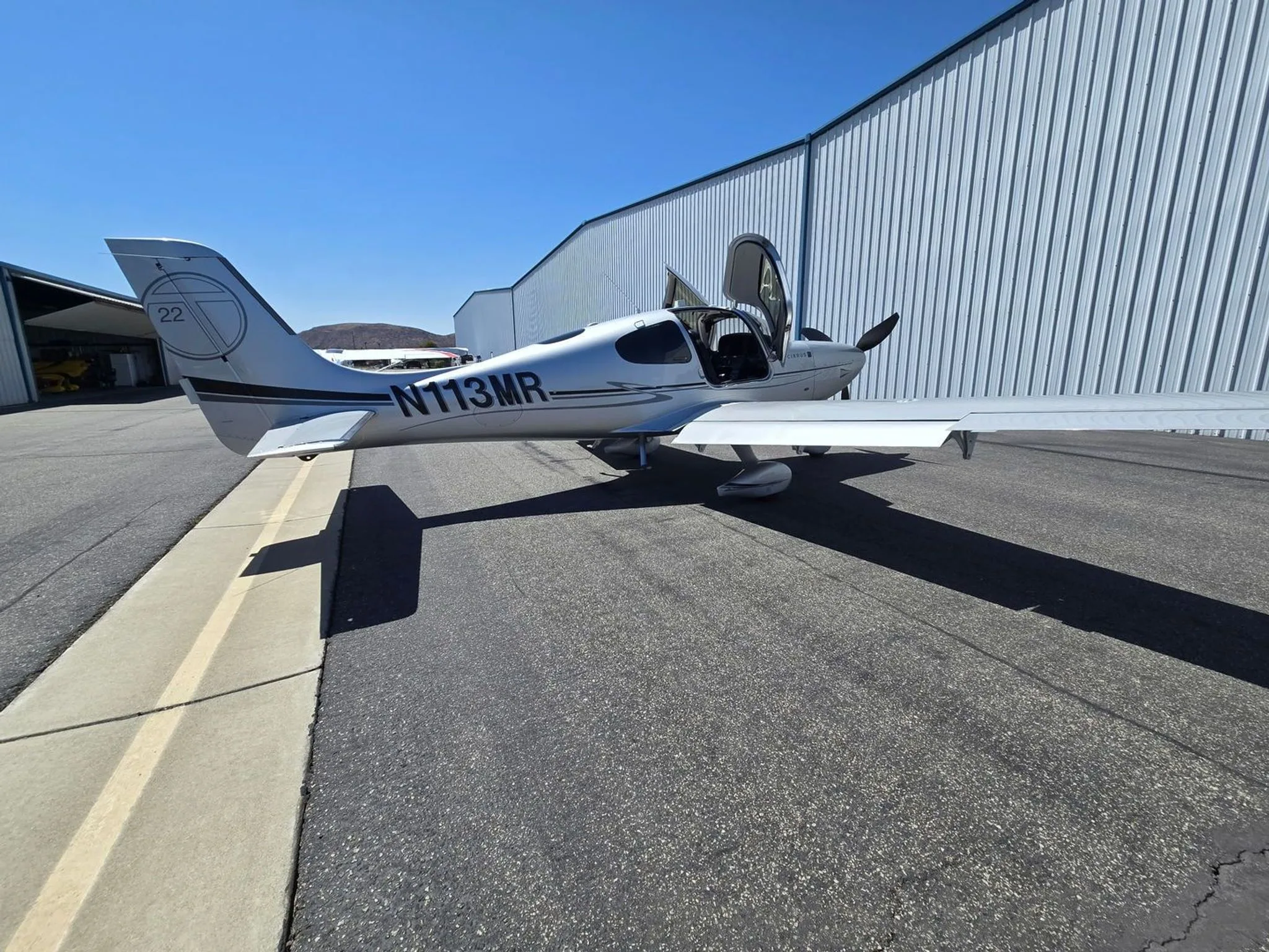


Free — save the SR22T to your watchlist and track it in one place.
More Cirrus SR22Tmanuals & documents
See all 21 →- Vantage 12 Pilot’s GuideV Speeds Reference
- Airworthiness Concern SheetAirworthiness Directives
- SERVICE BULLETIN HC-SB-30-390 Propeller - Spinner/Anti-ice Travel Tube InterferenceService Bulletins
- INSTRUCTIONS FOR INSTALLATION OF HARTZELL 4C1-F650A1/76C04(B)-0.6 PROPELLER ON CIRRUS SR22 AIRCRAFTMaintenance Manual
- INSTRUCTIONS FOR CONTINUED AIRWORTHINESS FOR HARTZELL 4C1-F650A1/76C04(B)-0.6 PROPELLER ON CIRRUS SR22T AIRCRAFTMaintenance Manual
- Supplemental Type Certificate SA03962ATSupplemental Type Certificate
- PILOT’S OPERATING HANDBOOK AND FAA APPROVED AIRPLANE FLIGHT MANUAL for the CIRRUS SR22Performance Data
- PILOT’S CHECKLIST SR22 G1 OR G2Checklist
- Service Bulletin TAT SB10-01Service Bulletins
- Hartzell Engine Technologies Service Bulletin 033Service Bulletins
- SCHEDULE OF AIRWORTHINESS DIRECTIVESAirworthiness Directives
- Multi-Function Display Pilot’s GuidePerformance Data
If you fly the Cirrus SR22T, you may also be researching these.



In this document
Airworthiness Limitations
This section outlines the mandatory airworthiness limitations that must be adhered to for the Cirrus SR22 Series. It includes specific intervals for inspections and maintenance tasks that are critical for ensuring the safety and reliability of the aircraft.
Turbonormalizer System Description and Operation
The turbonormalizer system utilizes two Kelly Aerospace turbochargers and an Absolute Pressure Controller to maintain manifold pressure. This section provides a detailed schematic and explanation of how the system operates, including the roles of the wastegates and intercoolers in managing engine performance.
Troubleshooting
This section provides a comprehensive troubleshooting guide for common issues related to the turbonormalizer system. It includes potential causes and remedies for problems such as engine starting issues, poor acceleration, and manifold pressure fluctuations.
Maintenance Practices
This section details the scheduled maintenance checks and overhaul/replacement schedules for critical components of the turbonormalizer system. It emphasizes the importance of documenting maintenance actions in the Service Time Record.
Appendix A - Torque Values
This appendix provides essential torque values for various components within the Cirrus SR22 Series, ensuring that maintenance personnel can perform tasks to the correct specifications.
Safety notes
- Momentary overboost to 32.0 inches of manifold pressure is acceptable for less than 2 minutes during operation.
- If overboost persists beyond normal operation, throttle should be retarded and the system checked for adjustments.
Full document text
TORNADO ALLEY TURBO, INC. 22-6460004 Continued Airworthiness Rev. C P a g e | 1 22 Sept 2011 Continued Airworthiness Manual For Cirrus Design SR22 Series Airplanes Turbonormalized per STC’s SA10588SC and SE10589SC TORNADO ALLEY TURBO, INC. 22-6460004 Continued Airworthiness Rev. C P a g e | 2 22 Sept 2011 LOG OF REVISIONS This document supersedes 215-10 release 08 Nov 2006. Pages Revision Date 1-41 A 10 APR 09 6 B 03 NOV 10 5, 19 C 22 SEPT 11 Revisions Lettered revisions of this document will be issued periodically. Each revision will cover the entire document. Change to data in the previous revisions will be identified by a revision bar in the outer margins of the page. Change bars will be shown only against the immediate prior revisions. Revision Distribution The latest revision of this document in its entirety will be posted at www.taturbo.com/drawings/ TORNADO ALLEY TURBO, INC. 22-6460004 Continued Airworthiness Rev. C P a g e | 3 22 Sept 2011 Intentionally Left Blank TORNADO ALLEY TURBO, INC. 22-6460004 Continued Airworthiness Rev. C P a g e | 4 22 Sept 2011 TABLE OF CONTENTS Subject Page Referenced Instructions for Continued Airworthiness and other Publications 5 AIRWORTHINESS LIMITATIONS 6 TURBONORMALIZER SYSTEM DESCRIPTION AND OPERATION 7 Fig. – 1 SR22 Turbonormalizing System Schematic 8 TROUBLESHOOTING 9 MAINTENANCE PRACTICES Overhaul And Replacement Schedule 17 Scheduled Maintenance Checks 17 Progressive Inspection Program 20 Turbochargers 22 Absolute Controller 22 Magnetos 22 Oxygen System 23 Absolute Controller Removal and Installation -Absolute Controller 24 Adjustment - Absolute Controller 24 Turbochargers Removal and Installation -Turbochargers 25 Master Wastegate Actuator Removal and Installation -Master Wastegate Actuator 25 Adjustment - Master Wastegate Actuator 26 Slave Wastegate Removal And Installation Of Slave Wastegate 26 Pressure Relief Valve Removal And Installation Of Pressure Relief Valve 26 Engine Removal and Overhaul - Engine 27 Installation - Engine 27 Inspection - Post Engine Overhaul / Installation 27 Servicing - Post Engine Overhaul / Installation 28 Operational Inspection - First Flight Run-Up 28 Adjustments -Post Engine Overhaul / Installation 29 Functional Inspection - Return to Service Flight 30 Post Return to Service Flight 30 Flooded Engine Start 30 Hot Engine Start 31 Fig. – 2a 32 Fig. – 2b 33 Fig. – 3a 34 Fig. – 3b 35 Fig. – 4 36 Fig. – 5a 37 Fig. – 5b 38 Appendix A - Torque values 39 TORNADO ALLEY TURBO, INC. 22-6460004 Continued Airworthiness Rev. C P a g e | 5 22 Sept 2011 Referenced Instructions for Continued Airworthiness and other Publications The latest revision to the following publications should be used in conjunction with this manual: Vendor Manual Title Part Number TATI Wastegate Functional Check and Adjustments 22-6460007 TATI Induction System Leak and Function Test 22-6460012 Hartzell Engine Technologies (formerly Kelly Aerospace) Kelly Aerospace Troubleshooting Reference Guide 400888-0000 GAMI GAMIjector Installation Procedure IP-2001-02 TCM Permold Series IO-550-A, B, C, G, N, P, R X30634A Cirrus Aircraft Maintenance Manual 13773-001 TATI Bulletin, Letter, or Instruction Number Subject Notes/Compliance SI08-01 Clean crankcase breather tube inlet on tailpipe Recommended SB08-02 Add anti-wear pad to PRV tube Optional SI08-04 Cabin Heat Augmenter/Tailpipe alternate inspection Recommended SI08-05 Air Filter cleaning method Recommended SB09-01 Inspection of exhaust for cracks Mandatory SB10-01 Alternate air door inspection/repair Mandatory SB10-02 Tailpipe hanger replacement Mandatory SI11-01 Exhaust slip joint inspection Recommended SI11-02 Fuel pump O-rings Recommended SI11-03 Turbocharger support system inspection and maintenance Highly Recommended SB11-04 Turbocharger inlet screens Highly Recommended SB11-05 Fine wire spark plugs Mandatory TATI service bulletins, letters, and instructions are available at www.taturbo.com/drawings/ TORNADO ALLEY TURBO, INC. 22-6460004 Continued Airworthiness Rev. C P a g e | 6 22 Sept 2011 TORNADO ALLEY TURBO, INC. 22-6460004 Continued Airworthiness Rev. C P a g e | 7 22 Sept 2011 TURBONORMALIZER SYSTEM DESCRIPTION AND OPERATION The Tornado Alley Turbonormalizing System (See Figure - 1) utilizes two Kelly Aerospace turbochargers with a Kelly Absolute Pressure Controller, and a Kelly pressure relief valve. The turbochargers are new generation turbochargers designed to provide the same boost as older design turbochargers but with lower compressor discharge temperatures. This increase in efficiency is due to the improved design of the compressor blades and compressor housing. However, to further reduce engine induction temperatures, two side baffle mounted intercoolers are also installed in the system. The Absolute Pressure Controller and wastegates work in conjunction with each other to provide proper boost pressure to the engine. The wastegate is actuated using engine oil pressure to actuate a small hydraulic cylinder which redirects the engine by-pass exhaust flow around the turbocharger. The absolute pressure controller utilizes an aneroid bellows and spring connected to a valve that regulates the amount of oil flowing out of the wastegate actuator hydraulic control cylinder. The aneroid bellows are located inside a housing that is connected to the output air produced by the compressors. As compressor outlet pressure increases, the normally closed oil control valve opens. When open, the valve allows metered oil to bypass the wastegate which, in turn, is spring loaded to the open position. Oil passing through the absolute controller is returned to the engine oil sump. The left hand wastegate is a master wastegate connected to a slave wastegate on the right side of the engine. The right hand wastegate
Show full textShow less
is the same as the left hand wastegate, but is slaved to the hydraulic actuator on the left hand wastegate. The two wastegates are mechanically synchronized and move in parallel with each other. Each wastegate incorporates a typical butterfly exhaust bypass valve. The master wastegate is spring loaded to the open position. Increasing oil pressure from the engine causes the actuator to work against the spring to close the butterfly valve. The wastegate is located in the exhaust system parallel with the turbocharger turbine. As the butterfly valve opens, it allows exhaust gasses to bypass the turbocharger turbine, thereby controlling the speed and output of the turbocharger. The wastegate helps provide even control of the turbocharger speed and output so that the engine can maintain sea level manifold pressure well into the flight levels. As turbocharger compressor outlet pressure rises, the aneroid bellows in the absolute pressure controller senses the increase in pressure. When at high engine speed and load and the proper absolute pressure is reached, the force on the aneroid bellows opens the normally closed metering valve. When the oil pressure in the wastegate actuator cylinder is lowered sufficiently, the wastegate actuator spring forces the mechanical linkage to open the wastegates. A portion of the exhaust gases then bypasses the turbocharger turbines, thus preventing further increase of turbocharger speed and holding the compressor outlet absolute pressure to the desired value. Conversely, at engine idle, the turbocharger runs slowly with low compressor pressure output; therefore, the low pressure applied to the aneroid bellows is not sufficient to affect the unseating of the normally closed metering valve. Consequently, engine oil pressure keeps the wastegates closed and all of the exhaust flows through the turbocharger turbine sections. The system is equipped with a magnetically latched alternate air door on the left side of the induction system. When any restriction of the air filter is encountered, such as from ice or ice crystal formation, the alternate air door will open automatically. A caution message or light will provide a message alert to the pilot that the alternate air door is open. The alternate air door provides an alternate path for warm air from the lower side of the engine compartment to go to both turbochargers when the air filter becomes blocked. After the air filter blockage is removed, the alternate air door may be closed by simply retarding the power lever momentarily and the door will re-latch automatically. In some instances, if there is an TORNADO ALLEY TURBO, INC. 22-6460004 Continued Airworthiness Rev. C P a g e | 8 22 Sept 2011 unusual surge in engine power, especially at high altitude, the alternate air door may become unlatched. In that event, again, simply retarding the throttle momentarily will re-latch the alternate air door. ENGINE CYLINDERS OIL FROM WASTEGATE ACTUATOR OVERBOARD THROUGH TAILPIPE ABSOLUTE PRESSURE CONTROLLER REGULATES OIL THROUGH WASTEGATE ACTUATOR EXHAUST SYSTEM OVERBOARD THROUGH TAILPIPE MANIFOLD PRESSURE GAUGE FROM ENGINE OIL PUMP TO ENGINE OIL SUMP TURBINE RAM AIR MECHANICAL LINKAGE EXHAUST AIR COMPRESSED AIR WASTEGATE ACTUATOR (SPRING LOADED OPEN-BOTH SIDES) LEGEND INDUCTION SYSTEM L/H INTERCOOLER R/H INTERCOOLER PRESSURE TO FUEL DISCHARGE NOZZLES ALT. AIR DOOR THROTTLE BODY UPPER DECK PRESSURE RELIEF VALVE TURBO SYSTEM COMPRESSOR WASTEGATE INDUCTION AIR FILTER SCHEMATIC CIRRUS SR-22 RAM AIR WASTEGATE Figure - 1 TORNADO ALLEY TURBO, INC. 22-6460004 Continued Airworthiness Rev. C P a g e | 9 22 Sept 2011 TROUBLESHOOTING To facilitate troubleshooting, the following information provides an explanation of how the turbonormalizer system works and points out some of the items that are affected by turbonormalizing. The information below follows the induction air as it enters and passes through the engine until it is expelled as exhaust gases. • Engine induction air is taken in through an opening in the nose bowl, ducted through a filter and into the compressors where it is compressed. • The pressurized induction air then passes through intercoolers, then the throttle body, and finally, the induction manifold into the cylinders. • The air and fuel are burned and exhausted to the turbocharger turbines. • The exhaust gases drive the turbines which, in turn, drive the compressors, thus completing the cycle. The compressors have the capability of producing manifold pressures in excess of 29.6 in. Hg. In order to maintain 29.6 inches of manifold pressure, a master wastegate is used on the left exhaust so that some of the exhaust from the left bank of cylinders will bypass the left turbine and be vented into the tailpipe. A slave wastegate on the right exhaust system is mechanically connected to the master wastegate. The right wastegate is used on the right exhaust so that some of the exhaust from the right bank of cylinders will bypass the right turbine and be vented into the tailpipe. It can be seen from studying the bulleted items above that anything which affects the flow of induction air into the compressors or the flow of exhaust gases into the turbines will increase or decrease the speeds of the turbines. A wastegate controller automatically maintains maximum allowable compressor discharge pressure anytime the turbines and compressors are capable of producing that pressure. The mechanical linkage between the wastegates is adjustable to ensure both wastegates control both turbochargers equally. At high altitude, part throttle, or low RPM, the exhaust flow is not capable of turning the turbine and compressor fast enough to maintain maximum compressor discharge pressure, and the wastegate will close to force all of the exhaust flow through the turbine. In normal operation at full throttle the wastegates will seldom if ever be fully closed. When the wastegate is fully closed, any change in turbocharger speed will mean a change in engine operation. Thus, any increase or decrease in turbine speed will cause an increase or decrease in manifold pressure and fuel flow. If turbine speed increases, the manifold pressure increases; if the turbine speed decreases, the manifold pressure decreases. Since the compression ratio approaches 3 to 1 at high altitude, any change in exhaust flow to the turbine or ram induction air pressure will be magnified proportionally by the compressor pressure ratio and the change in flow through the exhaust system. A. Momentary Overshoot Of Manifold Pressure Under some circumstances (such as rapid throttle movement especially with cold oil) it is possible that the engine can slightly overboost. This would most likely be experienced during takeoff roll or during a change to full throttle operation in flight. TORNADO ALLEY TURBO, INC. 22-6460004 Continued Airworthiness Rev. C P a g e | 10 22 Sept 2011 A slight overboost to 32.0 inches of manifold pressure is not considered detrimental to the engine as long as it’s duration is less than 2 minutes. No corrective action is required when momentary overboost corrects itself and is followed by normal engine operation as the engine warms up. However, if overboosting of this nature persists when oil temperature is normal or if the amount of overboost tends to exceed 3 inches or more, the throttle should be retarded to eliminate the overboost and the controller system including the wastegate and relief valve, should be checked for necessary adjustment or replacement of components. This troubleshooting section primarily references items covered for the turbonormalizing system. If it is not covered in this chart see Cirrus or TCM troubleshooting documents. Trouble Probable Cause Remedy Engine will not start. No indication of fuel flow and no fuel to engine. Check fuel controls for proper position, auxiliary fuel pump “BOOST” and operating, feed valves open, mixture full rich, throttle open, fuel filters open and visually check fuel tank level. Positive indication of fuel flow and engine is flooded. Execute a Flooded Engine Start. Positive indication of fuel flow, but no fuel to engine. Check for bent or loose fuel lines. Check for fuel at a fuel nozzle. If no fuel present at nozzle consult TCM X30634A - Permold Series I0-550- A, B, C, G, N, P, R. Engine starts but dies or will not idle properly. Vaporized fuel in system. (Most likely to occur in hot weather with a hot engine.) Refer to Hot Start Procedure in under Engine section part J. Obstructed air intake. Remove obstruction; service air filter. Inadequate fuel to fuel manifold valve. Set fuel control in “FULL RICH” position, turn auxiliary fuel pump “BOOST” check to be sure feed lines and filters are not restricted. Clean or replace defective components. Upper deck air supply to fuel discharge nozzle restricted or defective. Check for bent lines or loose connections. Tighten loose connections. Remove restrictions and replace defective components. Defective ignition system. Check engine data and verify which cylinders are affected by drop in EGT during single magneto operation. Check the spark plug and ignition lead indicated by which cylinder EGT drops on the operating magneto. TORNADO ALLEY TURBO, INC. 22-6460004 Continued Airworthiness Rev. C P a g e | 11 22 Sept 2011 Trouble Probable Cause Remedy (continued) Engine starts but dies or will not idle properly. Defective engine. Check compression and listen for unusual engine noises. Check oil filter for excessive metal. Repair engine as required. Engine Has Poor Acceleration. Fouled spark plugs. Check engine data and verify which cylinders are affected by drop in EGT during single magneto operation. Check the spark plug and ignition lead indicated by which cylinder EGT drops on the operating magneto. Idle mixture too lean. Readjust idle setting. Tighten adjustment screw to lean mixture and back off adjustment screw to richen mixture. Incorrect fuel-air mixture, worn control linkage, or restricted air filter. Tighten loose connections, replace worn elements of linkage. Service air filter. Engine lacks power, reduction in maximum manifold pressure or critical altitude. Incorrectly adjusted throttle control, “sticky” linkage or dirty air filter. Check movement of linkage by moving control from idle to full throttle. Make proper adjustments and replace worn components. Service air filter. Defective ignition system. Replace the defective parts. Check engine data and verify which cylinders are affected by drop in EGT during single magneto operation. Check the spark plug and ignition lead indicated by which cylinder EGT drops on the operating magneto. Improperly adjusted wastegate. Adjust wastegate per Wastegate Functional Checks and Adjustment document 22-6460007. Wastegate capillary tube plugged. Disconnect lines from controller to master wastegate and back flush Wastegate and lines with oil compatible solvent at 50 psi. Loose or damaged exhaust system. Inspect entire exhaust system to turbonormalizers for cracks and leaking connections. Tighten connections and replace damaged parts. TORNADO ALLEY TURBO, INC. 22-6460004 Continued Airworthiness Rev. C P a g e | 12 22 Sept 2011 Trouble Probable Cause Remedy (Continued) Engine lacks power, reduction in maximum manifold pressure or critical altitude. Loose or damaged intake manifolding. Inspect entire manifolding system for possible leakage at connections. Replace damaged components, tighten all connections and clamps. Restricted fuel discharge nozzles. Look at engine data and check fuel discharge nozzle that is indicated by higher than usual EGT and CHT at full power and full rich mixture. Malfunctioning turbocharger. Check for unusual noise in turbochargers. If malfunction is suspected remove tailpipe and/or air inlet connections and check rotor assembly, for possible rubbing in housing, damaged rotor blades or defective bearings. Replace turbocharger if damage is noted. Turbocharger inlet blocked. Remove obstruction. Fuel discharge nozzle defective. Inspect fuel discharge nozzle vent manifolding for leaking connections. Tighten and repair as required. Check for restricted nozzles and lines and clean and replace as necessary. Absolute Pressure Controller not getting enough oil pressure to close the wastegate. Check oil pump outlet pressure, oil filter and external lines for obstructions. Clean lines and replace if defective. Replace oil filter. Refer to Wastegate Functional Check and Adjustment document 22-6460007. Absolute Pressure Controller out of adjustment or defective. Adjust Absolute Pressure Controller or replace controller if defective. Defective Wastegate actuator. Replace actuator. Engine smokes (white smoke). Defective scavenge pump. Replace scavenge pump if defective. Master wastegate actuator leaking oil. Replace Master wastegate actuator. Turbo drain line (oil return to engine sump) plugged. Clean line and check valve. Replace either if defective. Turbocharger jammed. Replace turbocharger. Turbocharger bearing seals leaking. Replace turbocharger. Engine smokes (black smoke). Black smoke only below 1200 RPM idle rise too rich. Adjust idle mixture rise. Black smoke only above 1200 RPM engine driven fuel pump set too high. Decrease engine driven fuel pump fuel flow. TORNADO ALLEY TURBO, INC. 22-6460004 Continued Airworthiness Rev. C P a g e | 13 22 Sept 2011 Trouble Probable Cause Remedy Engine surges. Defective Absolute Pressure Controller. Replace Absolute Pressure Controller if defective. Wastegate actuator linkage binding. Replace if not adjustable. Reference document Wastegate Functional Check and Adjustment document 22-6460007 for induction leak test. Engine Power Increases Slowly Or Severe Manifold Pressure Fluctuations When Throttle Advanced. Pressure relief valve out of adjustment or defective. Replace Pressure relief valve if defective. Wastegate operation is sluggish. Lubricate and adjust wastegate. Correct cause of sluggish operation. Replace Wastegate if defective. Engine Power Increases Rapidly And Manifold Pressure Overboosts When Power Lever Advanced. Oil temperature not to operating standards. Warm up oil temperature and try again. Wastegate operation is sluggish. Lubricate and adjust wastegate. Correct cause of sluggish operation. Replace Wastegate if defective. Power lever advanced too rapidly. Advance power lever smoothly. Refer to Cirrus SR22 Service Manual. Verify oil pressure is in proper operating limits. Adjust oil pressure to proper limits. Pressure relief valve out of adjustment or defective. Factory adjustments required or replace pressure relief valve if defective. High Cylinder Head Temperature. Defective cylinder head temperature indication. Verify connections. If connected properly replace CHT probe. Engine timing incorrectly set. Reset timing to correct setting. Do GAMI lean test. Identify problem nozzle and replace or clean as appropriate. Engine baffles loose, or heat shields bent or missing. Install baffles or heat shields properly. Repair or replace if defective. LOP ops with insufficient manifold pressure or excessive fuel flow. Review downloaded engine data to verify correct operating technique per the AFMS is being used. Debris accumulated on cylinder cooling fins. Clean fins thoroughly. Alternate air door opens when power lever advanced. Power lever advanced too rapidly. Advance power lever slower. Air filter obstructed. Remove obstruction; Service or replace air filter. TORNADO ALLEY TURBO, INC. 22-6460004 Continued Airworthiness Rev. C P a g e | 14 22 Sept 2011 Trouble Probable Cause Remedy Engine Has Poor Acceleration, Runs Rough At Speeds Above Idle Or Lacks Power. Improper fuel-air mixture. Review downloaded engine data to verify correct operating technique per the AFMS is being used. Check intake manifold connections for leaks. Check fuel controls and linkage for setting and adjustment. Replace worn elements of control linkage. Service air filter. Loose hose connections. Tighten loose connections. Turbocharger rotor rubbing. Replace Turbocharger. Improperly adjusted or defective Absolute Pressure Controller. Adjust or replace Absolute Pressure Controller as required. Leak in turbonormalizer induction system. Correct cause of leaks. Repair or replace damaged parts. Engine oil viscosity too high for ambient air temperature. Replace oil with proper grade of oil. Exhaust system leakage. Inspect and repair excessive exhaust leaks. Ignition system defective. Check engine data and verify which cylinders are affected by drop in EGT during single magneto operation. Check the spark plug and ignition lead indicated by which cylinder EGT drops on the operating magneto. Replace damaged or misfiring plugs. Restricted fuel discharge nozzles. Look at engine data and check fuel discharge nozzle that is indicated by higher than usual EGT and CHT at full power and full rich mixture. High manifold pressure. Manifold pressure transducer is not functioning properly. Check that the manifold pressure gage reads the same as field barometric pressure with the engine not operating. (This is not the altimeter setting). Manifold pressure overshoot. (Most likely to occur when engine is accelerated too rapidly.) Smoothly move throttle about two- thirds open. Let engine accelerate and stabilize. Smoothly move throttle to full open. Manifold pressure is high and stays high after engine is warm. Absolute Pressure Controller sensing line broken or loose. Check upper deck sense line is connected and tight or replace if needed. TORNADO ALLEY TURBO, INC. 22-6460004 Continued Airworthiness Rev. C P a g e | 15 22 Sept 2011 Trouble Probable Cause Remedy (continued) Manifold pressure is high and stays high after engine is warm. Absolute Pressure Controller out of adjustment or defective. Adjust Absolute Pressure Controller or replace controller if defective. Wastegate linkage not functioning. Adjust or replace wastegate linkage per document 22-6460007 Wastegate Functional Check and Adjustment. Absolute Pressure Controller sensing line blocked. Remove blockage. Low fuel flow. Verify fuel flow is low at rated RPM and MAP. Adjust per Engine section, Part F. Verify that correct engine driven fuel pump is installed. Find the P/N and S/N on the engine driven fuel pump. Restricted flow to fuel metering valve. Check mixture control for full travel. Check for restrictions in fuel filters and lines, adjust control and clean filters. Replace damaged parts. Fuel control lever interference or out of adjustment. Check operation of throttle and mixture control for possible interference with other components. Adjust as required to obtain correct operation. Incorrect engine driven fuel pump adjustment and operation. Check and adjust fuel flow. See Engine section, part F. Replace defective pump. Fluctuating fuel flow. Fuel flow transducer or wiring failing. Verify this by determining if EGT’s fluctuate with fuel flow. If EGT’s do not fluctuate replace fuel flow transducer or repair wiring. Interference from ignition system. Operate engine on single magneto and identify which magneto is causing the interference. Manifold pressure fluctuating. Troubleshoot fluctuating manifold pressure. Unsatisfactory engine idle cut- off. Engine getting fuel with mixture in “IDLE CUT-OFF”. Adjust fuel control not in full “IDLE CUT-OFF” position. Check auxiliary fuel pump “OFF”. Check for leaking fuel manifold valve. Replace defective components. Low oil pressure on engine gage or high oil temperature. Insufficient oil in oil sump or using improper grade oil for prevailing ambient temperature. Add oil, or change oil to proper viscosity. Defective vernatherm valve. Check for defective vernatherm valve. See TCM X30634A - Permold Series I0-550-A, B, C, G, N, P, R. Replace valve if defective. TORNADO ALLEY TURBO, INC. 22-6460004 Continued Airworthiness Rev. C P a g e | 16 22 Sept 2011 Trouble Probable Cause Remedy (continued) Low oil pressure on engine gage or high oil temperature. Oil cooler restriction. Clean oil cooler. Debris under oil pressure relief valve. Check oil pressure adjuster seat for debris. Leaking, damaged, or loose oil line connection. Restricted screen or filter. Check for restricted lines and loose connections and cut the oil filter and inspect for contaminates or for partially plugged oil filter. Clean parts, tighten connections and replace defective parts. Oil pressure adjusted too low. Readjust oil pressure if necessary. Malfunctioning Turbocharger. Turbocharger rotor jammed or rubbing. Replace turbocharger. Turbocharger inlet blocked. Remove blockage. See section “Engine lacks power, reduction in maximum manifold pressure or critical altitude.” Engine has low critical altitude. See section “Engine lacks power, reduction in maximum manifold pressure or critical altitude.” Manifold pressure surges at altitude. Absolute Pressure Controller malfunctioning. Replace Absolute Pressure Controller. Wastegate capillary tube plugged. Disconnect lines from controller to master wastegate and back flush wastegate and lines with oil compatible solvent at 50 psi. Absolute Pressure Controller sensing line blocked. Remove sense line blockage. Induction system leaking. Eliminate any leaks per Induction System Leak and Function Test document 22-6460012. Leak in exhaust system. Adjust or repair exhaust system. Oil leaking or dripping from actuator drain. Acceptable drip. Continue monitoring drip. Actuator piston seal ruptured or leaking. Replace Actuator. Low manifold pressure at take- off. Absolute Pressure Controller out of adjustment or defective. Adjust Absolute Pressure Controller or replace controller if defective. Induction system leaking. Adjust or repair induction system. Wastegate capillary tube plugged. Disconnect lines from controller to master wastegate and back flush wastegate and lines with oil compatible solvent at 50 psi. Leak in exhaust system. Eliminate any leaks. Engine will not deliver rated power. See “Low manifold pressure at take-off” above. Rotating assembly bearing seizure. Free rotating assembly per Induction System Leak and Function Test document 22-6460012. TORNADO ALLEY TURBO, INC. 22-6460004 Continued Airworthiness Rev. C P a g e | 17 22 Sept 2011 MAINTENANCE PRACTICES TIME LIMITS AND MAINTENANCE CHECKS A. Overhaul And Replacement Schedule The following items must be overhauled or replaced at the following intervals unless otherwise noted. To ensure correct observation of these times, the date of removal, installation, or overhaul of such components as well as the airplane’s flight hours must be entered into the Service Time Record filed in the Airplane Maintenance Log. Item Interval Replc. O’haul Notes 1. Flexible Turbo System Lines On condition not to exceed 10 years X 2. Turbocharger See Note X Recommend overhaul turbocharger at 1000 hrs not to exceed 2000 hrs. 3. Wastegate See Note X Recommend overhaul Wastegate at 1000 hrs not to exceed 2000 hrs. 4. Absolute Pressure Controller See Note X Recommend overhaul Absolute Pressure Controller at 1000 hrs not to exceed 2000 hrs. 5. V-band clamps 450 hrs time in service X After 350 hrs if clamp is removed or first annual after 350 hrs. Whichever occurs first. 6. Magneto Pressurization Filter 3 years or 300 hours. X B. Scheduled Maintenance Checks Airframe Group Chap-Sect Reference Interval Initials 100 Special 1. All external surfaces for signs of exhaust leaks: Flat gray, gray-white or light gray powdering, or a sooty appearance indicate exhaust leakage. Signs of deterioration include warping, deformation, thinning, collapse, dents, cracking, tears, separation, scaling, weld separation, discoloration, corrosion, metal pitting or burn-through. TAT SB09-01 X 1 st 25 Hrs and every 50 Hrs after. 2. All external joints, clamps, and couplings for misalignment, warpage, broken, loose or missing fasteners, clamps, and abnormal wear. X 1st 25 Hrs 3. Visually inspect tailpipe heat exchanger, and shields for condition. X 1 st 25 Hrs 4. Visually inspect exhaust stack to flange interface for cracks in welds or weld heat affected area, blown out or missing gaskets. X 1 st 25 Hrs TORNADO ALLEY TURBO, INC. 22-6460004 Continued Airworthiness Rev. C P a g e | 18 22 Sept 2011 Airframe Group Chap-Sect Reference Interval Initials 100 Special 5. Visually inspect all welds and area adjacent to the weld for cracks or weld separation. X 1 st 25 Hrs 6. Visually inspect tailpipes, for erosion, thinning, bulging or burn through. X 1 st 25 Hrs 7. Visually inspect bracing, supports and support attach lugs on other structures for security. X 1 st 25 Hrs 8. Visually inspect surrounding structures for discoloration, heat damage, or burning. X 1 st 25 Hrs 9. Cold and Hot Air Hoses Visually Inspect for leaks, security, and condition. 50 Hrs 10. Engine Baffling and Seals Visual Inspection for cracks, tears, and rips. 50 Hrs 11. Turbocharger Mounting Bracket Visually Inspect for security and condition. 50 Hrs 12. Inspect the crankcase vent dump to the exhaust pipe for blockage and clean at each oil change or not more than 50 hrs. 50 Hrs 13. Engine Heat Shields Visually Inspect for security and condition. 50 Hrs 14. Engine Mount Isolators Visually Inspect for cracking, splitting, and general condition. X 15. Turbonormalizer Visually Inspect turbine for oil deposits, and turbine impeller damage. Visually Inspect compressor wheel for damage, interference, and free rotation. (Inspection may be accomplished by flexible bore scope or by removal of tailpipe.) Kelly Aerospace Troubleshooting Reference Guide 400888-0000 X 16. Turbonormalizer System Lines Visually Inspect for chafing, obstruction, security, and general condition. X 17. Wastegate and Absolute Pressure Controller Visually Inspect for security and condition. X 18. Tailpipe Heat Exchangers Pressure test or borescopic inspection of tailpipe sections adjacent to heat exchanger for signs of cracking. Repair or replace on condition. TAT SI08-04 X 19. Cabin Heat Mixing Valve Visually Inspect for security and condition. 200 Hrs 20. Induction System Filter Clean and re-oil filter at each inspection period or when filter is more than 50% covered by foreign material. (Due at annual or on condition, not less than each annual.) Clean per TATI Air Filter Cleaning Instruction No. TAT-SI08-05. X TORNADO ALLEY TURBO, INC. 22-6460004 Continued Airworthiness Rev. C P a g e | 19 22 Sept 2011 Airframe Group Chap-Sect Reference Interval Initials 100 Special 21. Alternate Air Door Visually Inspect for secure closing. Check for loose fasteners or rivets that may enter turbocharger. Verify that alternate air door indicator circuit is working by opening alternate air door and checking that alternate air door annunciator functions. Clean area around alternate air door. X All service interval times are to be referenced from initial installation of system or overhaul of turbonormalizing system, or after replacement of major exhaust components. Engine Group Chap-Sect Reference Interval Initials 100 Special 1. Engine Oil Drain and change every 50 hours or 6 months, whichever occurs first. 50 Hrs 2. Fuel Injection System Visually Inspect for leaks, security, and condition 50 Hrs 3. Vent Lines to Fuel Pump and Fuel Discharge Nozzles Visually Inspect for chafing, obstruction, security, and general condition. 50 Hrs 4. Fuel Discharge Nozzles Visually Inspect nozzles and manifold valve for fuel stains, security, and proper sealing of upper deck reference manifolds. Remove and clean injector nozzles every 5 years or 500 hours, whichever comes first. Remove, clean, and replace per GAMI Installation Procedure No. IP-2001-02. GAMI Installation Procedure No. IP-2001- 02 X On Condition 5. Spark Plugs RHB32E and RHB32S or equivalents per TCM SIL 03-2B installed as original equipment. Replace RHB32S spark plugs with RHB29E or equivalent heat range massive electrode spark plugs per TATI SB11- 05. If RHB29E spark plugs are not available RHB32E or equivalent heat range massive electrode spark plugs are acceptable. TATI SB11-05 Initially per TATI SB11-05 Thereafter, On Condition TORNADO ALLEY TURBO, INC. 22-6460004 Continued Airworthiness Rev. C P a g e | 20 22 Sept 2011 C. Progressive Inspection Program The following inspections are to be performed in addition to the Routine and detailed Inspection for the Engine Group defined in Chapter 5, Section 20 of the SR22 AMM. Engine Group Routine Inspection Criteria Chap-Sect Reference 1. Induction System Hoses and Couplings Visually Inspect for security, leaks, and condition. Refer to AMM 5-20 2. Turbochargers Visual inspection of turbines for carbonization, oil deposits, and turbine impeller damage. Visually Inspect compressor wheels for damage, interference, and free rotation. Refer to AMM 5-20 3. Turbocharger Mounting Brackets Visually Inspect for security and condition. Refer to AMM 5-20 4. Flexible Turbo System Lines Visually Inspect for chafing, obstruction, security, and general condition. Refer to AMM 5-20 5. Wastegate and Absolute Pressure Controller Visually Inspect for security and condition. Refer to AMM 5-20 6. Vent Lines to Fuel Pump and Discharge Nozzles Visually Inspect for chafing, obstruction, security, and general condition. Refer to AMM 5-20 7. Engine Heat Shields Visually Inspect for security and condition. Refer to AMM 5-20 8. Exhaust Muffler/Heat Exchanger Borescopic inspection of tailpipe sections adjacent to heat exchanger for signs of cracking. Repair or replace on condition. Refer to AMM 5-20 TORNADO ALLEY TURBO, INC. 22-6460004 Continued Airworthiness Rev. C P a g e | 21 22 Sept 2011 Engine Group Detailed Inspection Criteria Chap-Sect Reference 1. Induction System Hoses and Couplings Visually Inspect for security, leaks, and condition. Tighten hose clamps as required. Refer to AMM 5-20 2. Turbochargers Visually Inspect turbines for carbonization, oil deposits, and turbine impeller damage. Visually Inspect compressor wheels for damage, interference, and free rotation. Kelly Aerospace Troubleshooting Reference Guide 400888-0000 3. Turbocharger Mounting Brackets Visually Inspect for security and condition. Replace any cracked or damaged brackets. Refer to AMM 5-20 4. Flexible Turbo System Lines Visually Inspect for chafing, obstruction, security, and general condition. Refer to AMM 5-20 5. Wastegate and Absolute Pressure Controller Visually Inspect for security and condition. Lubricate wastegate butterflies with Mouse Milk® Refer to AMM 5-20 6. Vent Lines to Fuel Pump and Fuel Discharge Nozzles Visually Inspect for chafing, obstruction, security, and general condition. Refer to AMM 5-20 7. Engine Heat Shields Visually Inspect for security and condition. Refer to AMM 5-20 8. Exhaust Muffler/Heat Exchanger Borescopic inspection of tailpipe sections adjacent to heat exchanger for signs of cracking. Repair or replace on condition. Refer to AMM 5-20 TORNADO ALLEY TURBO, INC. 22-6460004 Continued Airworthiness Rev. C P a g e | 22 22 Sept 2011 TURBOCHARGERS The turbochargers are exhaust gas driven compressors, or air pumps, which provide high air mass flow to the engine intake manifold. Each turbocharger is composed of a turbine wheel, compressor wheel, turbine housing and compressor housing. The turbine, compressor wheel, and interconnecting drive shaft comprise one complete assembly and are the only moving parts in the turbocharger. Turbocharger bearings are lubricated with filtered oil supplied from the engine oil system. Engine exhaust gas enters the turbine housing to drive the turbine wheel. The turbine wheel, in turn, drives the compressor wheel, producing high density air entering the engine induction manifold. Exhaust gas is then dumped overboard through the exhaust outlet of the turbine housing and exhaust tailpipe. Air is drawn into the compressor through the induction air filter and is forced out of the compressor housing through a tangential outlet to the intake manifold. The degree of compression is varied by means of a wastegate valve, which varies the amount of exhaust gas allowed to bypass the turbine. ABSOLUTE PRESSURE CONTROLLER (APC) The Absolute Pressure Controller (APC) uses engine oil pressure to actuate the wastegate. The turbocharger is controlled by the wastegate, wastegate actuator, the absolute pressure controller and pressure relief valve (PRV). The wastegate bypasses engine exhaust gas around the turbonormalizer turbine inlet. The wastegate actuator, which is physically connected to the wastegate by mechanical linkage, controls the position of the wastegate butterfly valve. The absolute pressure controller controls the maximum turbonormalizer compressor discharge pressure. The pressure relief valve prevents an excessive pressure increase from the turbocharger compressor. The master wastegate actuator is spring-loaded to position the wastegate to the normally open position when there is not adequate oil pressure in the wastegate actuator power cylinder during engine shut down. When the engine is started, oil pressure is fed into the wastegate actuator power cylinder through an internal capillary tube. This automatically fills the wastegate actuator power cylinder and lines leading to the controller, blocking the flow of oil by normally closed metering and/or poppet valves. As oil pressure builds up in the wastegate actuator power cylinder, it overcomes the force of the wastegate open spring, closing the wastegate. When the wastegate begins to close, the exhaust gases causes the turbonormalizer to rotate faster, raising the turbonormalizer compressor outlet pressure. As the compressor outlet pressure rises, the aneroid bellows in the absolute pressure controller senses the increase in pressure. When at high engine speed and load and the proper absolute pressure is reached, the force on the aneroid bellows opens the normally closed metering valve. When the oil pressure in the wastegate actuator power cylinder is lowered sufficiently, the wastegate actuator opening spring forces the mechanical linkage to open the wastegate. A portion of the exhaust gases then bypasses the turbonormalizer turbine, thus preventing further increase of turbonormalizer speed and holding the compressor discharge absolute pressure to the desired value. Conversely, at engine idle, the turbonormalizer runs slowly with low compressor pressure output; therefore, the low pressure applied to aneroid bellows is not sufficient to affect the unseating of the normally closed metering valve. Consequently, engine oil pressure keeps the wastegate closed. The PRV will open to prevent any excessive pressure increase from the turbocharger compressor. MAGNETOS The magnetos installed on this aircraft are Bendix 25 series. These magnetos have been fitted with a magneto pressurization system to enable them to work at higher altitudes without cross firing due to the reduced resistivity of lower pressure atmosphere. This pressurization system consists of magneto housing TORNADO ALLEY TURBO, INC. 22-6460004 Continued Airworthiness Rev. C P a g e | 23 22 Sept 2011 gaskets, a calibrated bleed orifice, an inlet air filter, and tubing to rout pressurized air to the magnetos. The pressurization system gets the pressurized air from the induction system from just downstream of the turbochargers. In this application the timing is set at 21.5° BTDC ±0.5°. The inlet air filter will need to be changed periodically as shown in the Overhaul and Replacement Schedule listed under Maintenance Practices. OXYGEN SYSTEM Some of the turbonormalized SR22 aircraft have an optional oxygen system from Tornado Alley Turbo, Inc. This paragraph will pertain to only that system and not the Precise Flight system that is installed from the Cirrus factory. For oxygen systems installed per other STC’s , see the Instructions for Continued Airworthiness supplied with the STC. This oxygen system consists of a 77 cu. Ft. bottle installed on the aft baggage compartment bulkhead or in the tail of the aircraft with low pressure oxygen lines routed under the headliner to user ports installed overhead of the passengers. It has an on-off switch to operate the electric solenoid to turn the flow of oxygen on and off to the user ports. This solenoid is a normally closed solenoid so when power is removed the solenoid will shut off the supply of oxygen to the user ports. TORNADO ALLEY TURBO, INC. 22-6460004 Continued Airworthiness Rev. C P a g e | 24 22 Sept 2011 All torque values are located in Appendix A. ABSOLUTE PRESSURE CONTROLLER (APC) A. Removal and Installation -Absolute Pressure Controller 1) Disconnect and tag oil lines from controller and plug or cap open lines and fittings. 2) Disconnect compressor outlet pressure sensing lines from controller and plug or cap open lines and fittings. 3) Remove two bolts attaching controller to mounting bracket on firewall. 4) Remove controller from aircraft, being careful not to drop controller unit. 5) Installation of the controller may be accomplished by reversing the preceding steps. B. Adjustment – Absolute Pressure Controller Caution: With engine oil temperature at 170°F or greater, slowly open throttle and note maximum manifold pressure obtainable. -5 Absolute Pressure Controller Adjustment Procedure 1) Adjust the Absolute Pressure Controller so that the engine maintains 29.6 in. Hg at full throttle in flight with the oil temperature greater than 170°F. Normal in flight oil pressure should be between 42-52 psi. Note: Some aircraft have a different absolute pressure controller installed on them. This can be identified by a square head on the bottom of the controller instead of a hex head fitting. THIS IS THE ADJUSTER DO NOT TURN MORE THAN IS NEEDED FOR THE ADJUSTMENT. See the procedure below for the -10 absolute pressure controller. 2) Cut safety wire and remove plug from bottom of absolute controller. (It is normal for a small amount of oil to be encountered upon removal of the plug.) 3) Using a flat blade screw driver, rotate metering valve seat clockwise to increase manifold pressure and counterclockwise to decrease manifold pressure. Lightly tap the unit after each adjustment to seat internal parts. Note: When adjusting, rotate in VERY small increments as this is extremely sensitive. Approximately 13 degrees rotation will change the manifold pressure reading about one inch Hg. 4) Install the bottom plug in absolute pressure controller, then operate engine as in step “1” above to ascertain that adjustment has not caused an unacceptable change in manifold pressure. TORNADO ALLEY TURBO, INC. 22-6460004 Continued Airworthiness Rev. C P a g e | 25 22 Sept 2011 Note: When making adjustment on the ground, the hotter the engine gets, the lower the manifold pressure will be. 5) After each adjustment, the aircraft must be flight tested to check results. 6) Repeat this procedure until desired results are obtained. 7) Safety controller plug. -10 Absolute Pressure Controller Adjustment Procedure 1) Adjust the Absolute Pressure Controller so that the engine maintains 29.6 in. Hg at full throttle in flight with the oil temperature greater than 170°F. Normal in flight oil pressure should be between 42-52 psi. 2) Cut safety wire. 3) Using a 1/2” wrench, rotate metering valve seat clockwise to increase manifold pressure and counterclockwise to decrease manifold pressure. Lightly tap the unit after each adjustment to seat internal parts. Note: When adjusting, rotate in VERY small increments. Approximately ¼ turn will change the manifold pressure reading about one inch Hg. 4) Operate engine as in step “1” above to ascertain that adjustment has not caused an unacceptable change in manifold pressure. 5) After each adjustment, the aircraft must be flight tested to check results. 6) Repeat this procedure until desired results are obtained. 7) Safety wire adjuster. TURBOCHARGER A. Removal and Installation - Turbocharger 1) Loosen clamp and remove induction tubing from the front of the turbochargers. 2) Loosen clamp attaching tailpipe to turbine exhaust outlet and work wastegate and manifold from exhaust system. 3) Disconnect and tag oil lines from turbochargers and plug or cap open lines and fittings. 4) Remove bolts, washers, and nuts from exhaust flange that connects the turbocharger to the wastegate manifold assembly. 5) Remove the turbocharger from aircraft being careful not to drop the unit. 6) Installation may be accomplished by reversing the preceding steps and alignment of support rods. Caution: Pre-oil turbocharger before engine operation. MASTER WASTEGATE ACTUATOR A. Removal and Installation -Master Wastegate Actuator 1) Disconnect and tag oil lines from actuator and plug or cap open lines and fittings. Disconnect linkage to slave wastegate. 2) Remove bolts holding wastegate manifold assembly to exhaust system. TORNADO ALLEY TURBO, INC. 22-6460004 Continued Airworthiness Rev. C P a g e | 26 22 Sept 2011 3) Remove bolts, washers, and nuts attaching wastegate manifold assembly to the turbocharger. 4) Loosen clamp attaching tailpipe to turbine exhaust outlet and work wastegate and manifold from exhaust system. 5) Remove the assembly from aircraft being careful not to drop the unit. 6) Installation may be accomplished by reversing the preceding steps. Note: When installing the assembly, be sure the gaskets at inlet and outlet of valve are installed and are in good condition. Replace gaskets if damaged. B. Adjustment - Master Wastegate Actuator If adjustment of wastegate actuator is required, remove wastegate actuator in accordance with “Removal and Installation of Wastegate Actuator” instructions and send to an approved facility for repair or overhaul of wastegate actuators. SLAVE WASTEGATE A. Removal And Installation Of Slave Wastegate 1) Disconnect linkage to master wastegate. 2) Remove bolts holding wastegate manifold assembly to exhaust system. 3) Remove bolts, washers, and nuts attaching wastegate manifold assembly to the turbocharger. 4) Loosen clamp attaching tailpipe to turbine exhaust outlet and work wastegate and manifold from exhaust system. 5) Installation may be accomplished by reversing the preceding steps. Note: When installing the assembly, be sure the gaskets at inlet and outlet of wastegate are installed and are in good condition. Replace gaskets if damaged. PRESSURE RELIEF VALVE A. Removal And Installation Of Pressure Relief Valve 1) Remove bolts, washers, and nuts holding pressure relief valve to induction manifold assembly. 2) Remove pressure relief valve from induction manifold assembly. 3) Check condition of O-ring on face of pressure relief valve before installation. 4) Clean surface of induction manifold assembly, verify that the surface is smooth and free from nicks, gouges, or burrs that may damage the O-ring or prevent proper seal of the pressure relief valve. 5) Install the pressure relief valve by lining up the holes in the pressure relief valve with the holes in the induction manifold assembly and installing bolts, washers, and nuts in the same orientation as when removed. TORNADO ALLEY TURBO, INC. 22-6460004 Continued Airworthiness Rev. C P a g e | 27 22 Sept 2011 ENGINE A. Removal and Overhaul - Engine If the engine is to be removed, the turbochargers and their accessories should be removed in accordance with the following steps before removing engine mount bolts. All other procedures for engine removal listed in the Cirrus SR22 service manual apply. 1) Disconnect hoses to the intercoolers. 2) Remove wastegates in accordance with “Removal and Installation of Master Wastegate Actuator” and “Removal and Installation of Slave Wastegate” instructions. 3) Remove turbochargers in accordance with “Turbocharger Removal and Installation” instructions. Note: The replacement normally aspirated IO-550-N engine must be modified before installation as a turbonormalized Cirrus engine. Therefore turbonormalized engines must be overhauled by a facility approved by Tornado Alley Turbo, Inc. (TATI) and in accordance with procedures established by TATI. Installation of new or overhauled engines in existing turbonormalized aircraft requires installation of components at TATI or a facility approved by TATI. Overhaul turbochargers, MPC, wastegates, PRV, and fuel pump at the same time as engine overhaul. Contact TATI for a current list of approved overhaul facilities for engine and components. Keep fuel injectors in proper cylinders. B. Installation – Engine Before installing the engine, the aft accessories should be installed prior to attaching the engine to the engine mounts per the Cirrus maintenance manual. The turbochargers and exhausts can then be installed on the engine. 1) Install the turbochargers in accordance with “Turbocharger Removal and Installation” instructions. 2) Install the wastegates per “Removal and Installation of Master Wastegate Actuator” and “Removal and Installation of Slave Wastegate” instructions. 3) Connect all hoses and induction system. C. Inspection - Post Engine Overhaul / Installation After overhaul and reinstallation of the engine and turbonormalizing system a final inspection is required. Inspect the following for security, signs of chaffing, leaking, and general condition: 1) All hose connections, routing, and security. 2) All clamps and couplings for proper engagement and alignment. 3) Induction tubing for current and possible chafe problems. 4) Tightness of all exhaust mounting hardware and v-band clamps. 5) Clearance of exhaust through cowling and below firewall. 6) Wiring chafe and heat related problems. 7) Engine probe wiring to exhaust clearance. 8) Cylinder lower fuel drain plumbing clearance to exhaust and heat shields. 9) Heat shield clearance off of exhaust components. 10) Turbo supports for security and safety wire. TORNADO ALLEY TURBO, INC. 22-6460004 Continued Airworthiness Rev. C P a g e | 28 22 Sept 2011 11) Wastegate linkage clearance and safety wire. 12) Turbo air inlet SCEET to front cowling clearance. 13) Throttle, propeller, and mixture control lever full travel. D. Servicing - Post Engine Overhaul / Installation (Before First Engine Start) After overhaul and reinstallation of the engine and turbonormalizing system, pre-oil the turbochargers as described below. 1) Remove all lower spark plugs. 2) Ground all ignition leads to engine. 3) Fuel Selector to “OFF”. 4) Clear engine and propeller area from obstacles. 5) Ensure proper oil level. 6) Turn on battery power. 7) With security person outside, crank engine and monitor indicated oil pressure. Crank engine for no more than 30 seconds at a time. When 12 psi or more is consistently indicated on the oil pressure indicator the turbo will be considered to be pre-oiled. 8) Turn off battery power. 9) Reinstall spark plugs and leads and visually inspect the engine compartment for any oil leaks. 10) Conduct a fuel prime operation check by putting the Fuel Selector to either tank, and mixture full rich. 11) Turn on battery. 12) Activate fuel prime switch and observe fuel flow for brief positive indication of fuel flow. 13) Turn off battery. 14) Inspect engine area for any fuel leaks, paying careful attention to the fuel discharge nozzles and fuel lines. E. Operational Inspection - First Flight Run-Up Perform the following Run-Up Procedure prior to first flight after reinstallation of turbonormalizing system during overhaul or maintenance of turbonormalizing system components. With upper and lower cowling removed, fireguard/observer present: Note: Make sure turbochargers are pre-oiled under Servicing – Post Engine Overhaul/Installation. 1) Start engine using normal starting procedures. 2) Keeping RPM below 1700 rpm, monitor oil pressure, fuel flow, manifold pressure, and engine temperatures for normal operation. 3) Run engine for a short time, only long enough to check all indications and ensure no fuel or oil leakage. 4) Shut engine down, inspect engine and turbo system for any sign of leakage, chafing, or heat damage. 5) Install complete cowling. 6) Perform normal engine start and operation to achieve proper operating temperatures. 7) Perform magneto operational check. 8) Perform high power operation check. TORNADO ALLEY TURBO, INC. 22-6460004 Continued Airworthiness Rev. C P a g e | 29 22 Sept 2011 9) Monitor engine operating parameters and make adjustments as described in section F. 10) After achieving the desired operating parameters, inspect the engine compartment for evidence of leaking, chafing, and heat damage. 11) Release aircraft for return to service flight. F. Adjustments -Post Engine Overhaul / Installation Make the following adjustments as required prior to first flight after reinstallation of turbonormalizing system during overhaul or maintenance of turbonormalizing system components. 1) Engine Setup a) RPM All adjustments need to be made at full operating RPM (2700). Fuel Flow, Manifold Pressure, Turbo Inlet Temperature, and Oil Pressure, to be measured at full RPM. If needed, make adjustments at the propeller governor. Ensure normal operating oil temperature before making RPM adjustments. Note: Every airplane may not make full RPM during static ground run. Make adjustments as close as possible, then fly and readjust after flight per pilot information. b) Fuel Flow For the IO-550-N turbonormalized engine, the target full power (RPM and MAP) fuel flow is 35 GPH ± 1.0 GPH. Normally, full power fuel flow will be 36 GPH. To achieve these indicated target amounts adjustments may need to be made at the high RPM aneroid adjustment screw. Because of the special combination of fuel nozzles and turbonormalized fuel pump, the TCM service bulletin is a guide for adjustments, but the target GPH is the desired outcome. If an adjustment is necessary, the aneroid adjuster screw will need to be turned OUT (CCW) for an increase in fuel flow, or IN (CW) for a decrease in fuel flow. One complete turn will equal approximately 1.5 GPH. To make an adjustment loosen jam nut, turn screw, snug up jam nut. Note: Fuel flow is proportional to RPM, and Manifold Pressure. Given targets are set at engine operating oil temperature, engine operating RPM, and indicated 29.6 inches of manifold pressure. During the run-up, the oil temperature should be not less than 170° F; cooler oil will make higher manifold pressure which will make higher fuel flow. c) Manifold Pressure Maximum manifold pressure in cruise flight is 29.6 inches at full throttle with normal engine operating oil temperature. Make adjustments to manifold pressure according to “Absolute Controller Adjustments” section above. Note: The APC pressure set point will vary slightly with engine oil temperature and oil pressure. If the oil temperature is cooler, the TORNADO ALLEY TURBO, INC. 22-6460004 Continued Airworthiness Rev. C P a g e | 30 22 Sept 2011 manifold pressure may indicate higher. Be sure to make adjustments with the engine oil temperature at or above 170° F. d) Oil Pressure Normally, there should not be a need to make oil pressure adjustments, but if the oil pressure is below 20 PSI at idle, the oil pressure must be increased enough to keep adequate oil flow through the turbo at idle speeds. The turbo inlet oil pressure check valve is preset to 10 PSI. If oil pressure is lower than this, the turbo will “starve” for oil. Note: Make oil pressure adjustment according to TCM maintenance manual instructions. G. Functional Inspection - Return to Service Flight Perform the following Return to Service Flight after reinstallation of turbonormalizing system during overhaul or maintenance of turbonormalizing system components. 1) Perform normal start up, taxi, engine parameter checks and any ground operational checks not related to the turbo system. 2) Utilizing normal Cirrus before flight checklist perform additional full power performance operational check prior to releasing the brakes for take off. Take note of: engine RPM, fuel flow, TIT, manifold pressure, and oil temperature. 3) Depending on oil temperature the parameters may vary. Optimally, 2700 RPM, 29.6 inches MP, 35 GPH ± 1.0 GPH at normal operating oil temperature. 4) Because of a direct correlation between oil temperature and manifold pressure at lower than normal operating oil temperature, manifold pressure may indicate higher than redline. 5) Because of a direct correlation between manifold pressure and fuel flow higher manifold pressure will give higher fuel flow. 6) At full power and full rich mixture, the TIT will normally be between 1250-1330° F. 7) Utilize normal Cirrus engine break-in procedures. Keep in mind the turbo parameters and the added system components. H. Post Return to Service Flight Inspections 1) After first flight, recheck torque on V-band clamps. Use caution to not over torque the V-band clamps. 2) Inspect engine compartment for evidence of leaking, chafing, and heat damage. I. Flooded Engine Start Procedure 1) Mixture to “Idle Cut-Off”. 2) Throttle to “Full Open”. 3) Crank engine and once the engine starts move mixture to “Full Rich”. 4) Adjust throttle for engine idle between 800-1000 RPM. TORNADO ALLEY TURBO, INC. 22-6460004 Continued Airworthiness Rev. C P a g e | 31 22 Sept 2011 J. Hot Engine Start Procedure 1) Mixture to “FULL RICH”. 2) Open throttle slightly to the point of normal engine idle. 3) Simultaneously engage electric boost pump to “BOOST” and the starter switch to “START”. 4) When the engine starts release the starter switch. 5) Adjust the throttle to normal idle of 800-1000 RPM. 6) On very hot days leave the electric boost pump switch on “BOOST” during taxi. TORNADO ALLEY TURBO, INC. 22-6460004 Continued Airworthiness Rev. C P a g e | 32 22 Sept 2011 PRESSURE RELIEF VALVE MP CONTROLLER SCAVENGE PUMP L/H TAILPIPE FUEL MANIFOLD VALVE L/H INTERCOOLER WASTEGATE ACTUATOR FUEL PUMP UPPER DECK REFERENCE FIREWALL HEATER BOX, HEATER VALVE TURBO TUBULAR EXHAUST SHOWN; HALF STAMP NOT SHOWN ALTERNATE AIR DOOR CURVED TAILPIPE SHOWN; STRAIGHT TAILPIPE NOT SHOWN LATERAL SUPPORT BRACKET NOT SHOWN IN THIS VIEW VERTICAL SUPPORT ROD Figure - 2a TORNADO ALLEY TURBO, INC. 22-6460004 Continued Airworthiness Rev. C P a g e | 33 22 Sept 2011 PRESSURE RELIEF VALVE FUEL MANIFOLD VALVE L/H INTERCOOLER UPPER DECK REFERENCE CROSSOVER TUBE MP CONTROLLER STARTER DRIVE L/H STRAIGHT TAILPIPE WASTEGATE ACTUATOR FUEL PUMP FIREWALL HEATER BOX, HEATER VALVE TURBO HALF STAMP EXHAUST ALTERNATE AIR DOOR LATERAL SUPPORT BRACKET NOT SHOWN IN THIS VIEW VERTICAL SUPPORT ROD Figure – 2b TORNADO ALLEY TURBO, INC. 22-6460004 Continued Airworthiness Rev. C P a g e | 34 22 Sept 2011 NUT; MS21046C6 (x4) V-BAND CLAMP; 995CS-0339 (x2) L/H TURBO ASSEMBLY; ETI-SR22-2000 L/H WASTEGATE DUMP; ETI-G2-110-105 WASTEGATE OUTLET; ETI-SR22-109-1 (x2) NUT; MS21046C4 (x16) L/H TAILPIPE; ETI-G2-110-L R/H TAILPIPE; ETI-G2-110-R R/H LATERAL SUPPORT; ETI-G2-600-121 BOLT; AN8C13A NUT; MS20500-428 (x24) GASKET; 652458 (x6) PIN; MS20392-1C19 NUT; MS21046C6 (x4) R/H TURBO ASSEMBLY; ETI-SR22-1300 WASTEGATE LINKAGE; ETI-SR22-111-1 COTTER PIN; BACP18BC02A02P (x2) WASHER; NAS1149C0663R (x8) L/H EXHAUST; ETI-G2-103-1 BOLT; AN4C11A (x24) BOLT; AN4C12A (x8) L/H LATERAL SUPPORT; ETI-G2-600-120 WASTEGATE ASSEMBLY; 470842-9004 GASKET; 1550148-2 (x4) WASHER; NAS1149C0463R (x32) BOLT; AN8C13A (x2) L/H TURBO SUPPORT; ETI-SR22-2200 LOWER SUPPORT BRACKET ; ETI-G2-600-A BOLT; AN8C12A (x2) PIN; MS20392-1C25 FWD R/H EXHAUST; ETI-G2-100-1 WASTEGATE; 477233-0003 R/H WASTEGATE DUMP; ETI-G2-110-106 BOLT; AN8C14A BOLT; AN8C12A (x2) R/H TURBO SUPPORT; ETI-SR22-2300 WASHER; NAS1149C0663R (x8) Figure - 3a TORNADO ALLEY TURBO, INC. 22-6460004 Continued Airworthiness Rev. C P a g e | 35 22 Sept 2011 Figure - 3b TORNADO ALLEY TURBO, INC. 22-6460004 Continued Airworthiness Rev. C P a g e | 36 22 Sept 2011 TO MAIN FUEL SCREEN TO LEFT INTERCOOLER HIGH RPM FUEL FLOW ADJUSTMENT: CCW = INCREASE CC = DECREASE Figure - 4 TORNADO ALLEY TURBO, INC. 22-6460004 Continued Airworthiness Rev. C P a g e | 37 22 Sept 2011 OUT TO UDP IN IN OUT OUT IN IN OUT OUT IN OUT ACC. PAD OUT OUT IN OUT OUT IN IN OUT IN TO UDP OUT TO UDP IN IN IN B IN B OUT IN IN OUT OUT IN OUT OUT IN OUT OUT ACC. PAD OUT IN IN OUT IN TO UDP Figure – 5a Figure – 5b TORNADO ALLEY TURBO, INC. 22-6460004 Continued Airworthiness Rev. C P a g e | 38 22 Sept 2011 Appendix A. Component Specific Torque Specifications Torque Value SIZE FASTENER IN./LB. FT./LB. MODELS AFFECTED Miscellaneous Hardware (see Note 5) #2‐56 Screw‐ Heatshield MCU 1.4 ‐ 2.6 N/A All Turbonormalized models #10‐32 Bolt‐ Retaining Inner Cylinder Baffles 36 ‐ 50 3.0 ‐4.2 All Turbonormalized models 10028H Clamp‐ Heatshield exhaust 45 ‐ 50 3.7 ‐ 4.1 All Turbonormalized models 10040H Clamp‐ Induction tube 45 ‐ 50 3.7 ‐ 4.1 All Turbonormalized models 10048H Clamp‐ Intake tube 45 ‐ 50 3.7 ‐ 4.1 All Turbonormalized models 10016H Clamp‐ Heatshield engine mount 45 ‐ 50 3.7 ‐ 4.1 All Turbonormalized models Miscellaneous Fuel Injection (see Note 5) .38‐24 Nut‐ Fuel Drain Line Snug nut finger tight to set seal between nut and male connector, then tighten additional 3/4 to 1 turn. All engine models .25‐48 Nut‐Aneroid stem jam 25 ‐ 30 2.1 ‐ 2.5 All Turbonormalized models #3 (.38‐24) Nut‐ "B", Controller reference line 70 ‐ 105 5.8 ‐ 8.7 All Turbonormalized models #6 (.5625‐18) Nut‐ "B", upper deck reference tube 150 ‐ 195 12.5 ‐ 16.2 All Turbonormalized models .31‐24 Nut‐ Mixture control lever to shaft 100 ‐ 120 8.3 ‐ 10.0 All engine models .50‐24 Nut‐ Air reference sleeve "B" nut to air reference line Snug nut finger tight to set seal between nut and male connector, then tighten additional 3/4 to 1 turn. All Turbonormalized models .125‐27 Nozzle‐ Fuel injector (with anti‐seize compound) 55 ‐ 65 4.6 ‐ 5.4 All Turbonormalized models .31‐32 Nut‐ Fuel injection line 40 ‐ 45 3.3 ‐ 3.7 All Turbonormalized models Crankcase (see Note 5) .31‐24 Nut‐ Magneto Flange 100 ‐ 120 8.3 ‐ 10.0 All engine models .31‐18 Bolt‐ Oil sump flange 155 ‐ 175 12.9 ‐ 14.6 All engine models .25‐20 Screw‐ Rocker box cover 55 ‐ 65 4.6 ‐ 5.4 All engine models Exhaust .25‐28 Nut‐ Exhaust manifold flange to cylinder 100 ‐ 110 8.3 ‐ 9.2 All engine models .38‐24 Nut‐ Turbocharger to exhaust flange 275 ‐ 325 22.9 ‐ 27.1 All Turbonormalized models .250‐28 Nut‐ All .250 bolts to attach support brackets 90 ‐ 100 7.5 ‐ 8.3 All Turbonormalized models #10‐32 Bolt‐ Turbo heatshield 36 ‐ 50 3.0 ‐ 4.2 All Turbonormalized models #8‐32 Screw‐ Turbo heatshield 17.5 ‐ 22.5 1.5 ‐ 4.2 All Turbonormalized models .250‐20 Bolt‐ Turbo support to cylinder head 75 ‐ 85 6.3 ‐ 7.1 All Turbonormalized models TORNADO ALLEY TURBO, INC. 22-6460004 Continued Airworthiness Rev. C P a g e | 39 22 Sept 2011 Appendix A. Component Specific Torque Specifications Torque Value SIZE FASTENER IN./LB. FT./LB. MODELS AFFECTED Exhaust (cont’d) .3125‐24 Nut‐ All .312 nuts for turbo support 180 ‐ 220 15.0 ‐ 18.3 All Turbonormalized models .3125‐24 Nut‐ Spring turbo support Tighten the nut to compress the spring to 3/4 of expanded height All Turbonormalized models .25‐28 Nut‐ Exhaust coupling "V" band clamp 60 ‐ 65 5.0 ‐ 5.4 All Turbonormalized models Turbo (see Note 2) .3125‐18 Bolt‐ Turbo oil inlet adapter 155 ‐ 175 12.9 ‐ 14.6 All Turbonormalized models .376‐15 Bolt‐ Turbo oil outlet adapter 220 ‐ 260 18.3 ‐ 21.7 All Turbonormalized models .125‐27 Valve‐ Turbo oil inlet 100 ‐ 105 8.3 ‐ 8.7 All Turbonormalized models .3125‐18 Bolt‐ Turbo compressor housing 130 ‐ 140 10.8 ‐ 11.6 All Turbonormalized models .3125‐18 Bolt‐ Turbo hot section housing 140 ‐ 150 11.6 ‐ 12.5 All Turbonormalized models Fitting and Hose connection (see Note 1 & 6) .125‐27 pipe Fitting‐ 1/8 Pipe thread 60 ‐ 80 5.0 ‐ 6.7 Plus alignment .250‐18 pipe Fitting‐ 1/4 Pipe thread 130 ‐ 150 10.8 ‐ 12.5 Plus alignment .375‐18 pipe Fitting‐ 3/8 pipe thread 185 ‐ 215 15.4 ‐ 18.0 Plus alignment .44‐20 #4 Aluminum 90 ‐ 105 7.5 ‐ 8.7 Bulkhead fitting (with o‐ring) .44‐20 #4 Steel 110 ‐ 130 9.1 ‐ 10.8 Bulkhead fitting (with o‐ring) .56‐18 #6 Aluminum 125 ‐ 145 10.4 ‐ 12.0 Bulkhead fitting (with o‐ring) .56 ‐18 #6 Steel 225 ‐ 275 18.7 ‐ 22.9 Bulkhead fitting (with o‐ring) .75‐16 #8 Aluminum 240 ‐ 280 20.0 ‐ 23.3 Bulkhead fitting (with o‐ring) .75‐16 #8 Steel 400 ‐ 450 33.3 ‐ 37.5 Bulkhead fitting (with o‐ring) .44‐20 #4 Aluminum 90 ‐ 105 7.5 ‐ 8.7 Straight thread (with o‐ring) .44‐20 #4 Steel 110 ‐ 130 9.1 ‐ 10.8 Straight thread (with o‐ring) .56‐18 #6 Aluminum 125 ‐ 145 10.4 ‐ 12.0 Straight thread (with o‐ring) .56 ‐18 #6 Steel 225 ‐ 275 18.7 ‐ 22.9 Straight thread (with o‐ring) .75‐16 #8 Aluminum 240 ‐ 280 20.0 ‐ 23.3 Straight thread (with o‐ring) .75‐16 #8 Steel 400 ‐ 450 33.3 ‐ 37.5 Straight thread (with o‐ring) #3 (.38‐24) Brass / Aluminum fitting 70 ‐ 105 5.8 ‐ 8.75 Hose fitting "B" nut #3 (.38‐24) Steel fitting 95 ‐ 140 7.9 ‐ 11.6 Hose fitting "B" nut #4 (.4375‐20) Brass / Aluminum fitting 100 ‐140 8.3 ‐ 11.6 Hose fitting "B" nut #4 (.4375‐20) Steel fitting 135 ‐ 190 11.2 ‐ 15.8 Hose fitting "B" nut #6 (.5625‐18) Brass / Aluminum fitting 150 ‐ 195 12.5 ‐ 16.2 Hose fitting "B" nut #6 (.5625‐18) Steel fitting 215 ‐ 280 17.9 ‐ 23.3 Hose fitting "B" nut #8 (.750‐16) Brass / Aluminum fitting 270 ‐ 350 22.5 ‐ 29.1 Hose fitting "B" nut #8 (.750‐16) Steel fitting 470 ‐ 550 39.1 ‐ 45.3 Hose fitting "B" nut TORNADO ALLEY TURBO, INC. 22-6460004 Continued Airworthiness Rev. C P a g e | 40 22 Sept 2011 NOTE 1 Bulkhead fittings consist of fitting with o‐ring and jam nut. To properly install the fitting, thread jam nut past first set of threads and to the end of the second set, slide o‐ring over the long end to rest in the groove between threads. Thread the fitting into the receiving port until o‐ring makes contact witht he port seat. Turn fitting for alignment while ensuring o‐ring remains in the groove without contacting threads. Tighten jam nut to specified torque above. 2 Turbo compressor housing and hot section housing require the application of Locktite 545 be placed on the threads prior to installation of bolts. 3 Use locking devices as required after installation and applying the specified torque values. 4 The turbo oil inlet valve requires special torque of 105 inch lbs plus the application of Locktite 545 prior to installation. 5 Specific requirements as stated in TCM SB96‐7C Torque Limits ( or later revision) will take precedence over this document as it relates to TCM components. 6 Utilize accepted procedures and techniques for the installation of all hoses in reguards to alignment and support. Back up all fittings when tightening hoses.
What's in the Cirrus SR22T TCDS
A Type Certificate Data Sheet (TCDS) is the FAA's record of what an aircraft type was approved as. It is the source of truth for weights, seating, fuel and the rules the design was certified against. Expand any line to see what it means.
1,001 Cirrus SR22T parts for sale
See all →
Parts listed for sale by vetted eBay sellers — confirmed on eBay at checkout.