Maintenance Manual with Illustrated Parts Catalog
Cirrus SR22T · Maintenance Manual
Overview
This Maintenance Manual with Illustrated Parts Catalog is designed for the Cirrus SR22 aircraft, specifically detailing the Keith Products air-conditioning system. It provides comprehensive instructions for maintenance technicians on servicing, troubleshooting, and maintaining the air-conditioning system. The manual includes a detailed description of the system's components, operational procedures, and troubleshooting charts to assist in diagnosing issues. It also outlines the necessary tools and equipment required for various maintenance tasks, ensuring that technicians have the information needed to perform their duties effectively. The manual is essential for ensuring the air-conditioning system operates efficiently and safely, contributing to the overall performance of the Cirrus SR22.
- The air-conditioning system uses R134a refrigerant and Polyolester Oil (ISO 68).
- Always wear safety goggles when servicing the refrigerant system to prevent eye injury.
- The air-conditioning system must be evacuated before charging to remove moisture and air.
- Do not operate the air-conditioning system with the condenser air inlet or outlet blocked.
- Follow proper procedures for discharging and charging the system to comply with federal regulations.
Document
Source
Originally published by acethermalsystems.com. Sprinkle hosts a reference copy with an added summary, specifications and searchable full text.
Document details
- Type
- Maintenance Manual
- Year
- 2004
- Pages
- 76
- File size
- 2.4 MB
- Publisher
- acethermalsystems.com
Common. One of the most common aircraft types we track.
Most owners only have the POH. Here's the essential set for the Cirrus SR22T.
- Pilot's Operating Handbook / AFM
- Checklist
- Maintenance Manual
- Parts Catalog (IPC)
- Systems & Wiring
- Service Bulletins
- Type Certificate (TCDS)
Cirrus SR22T for sale now
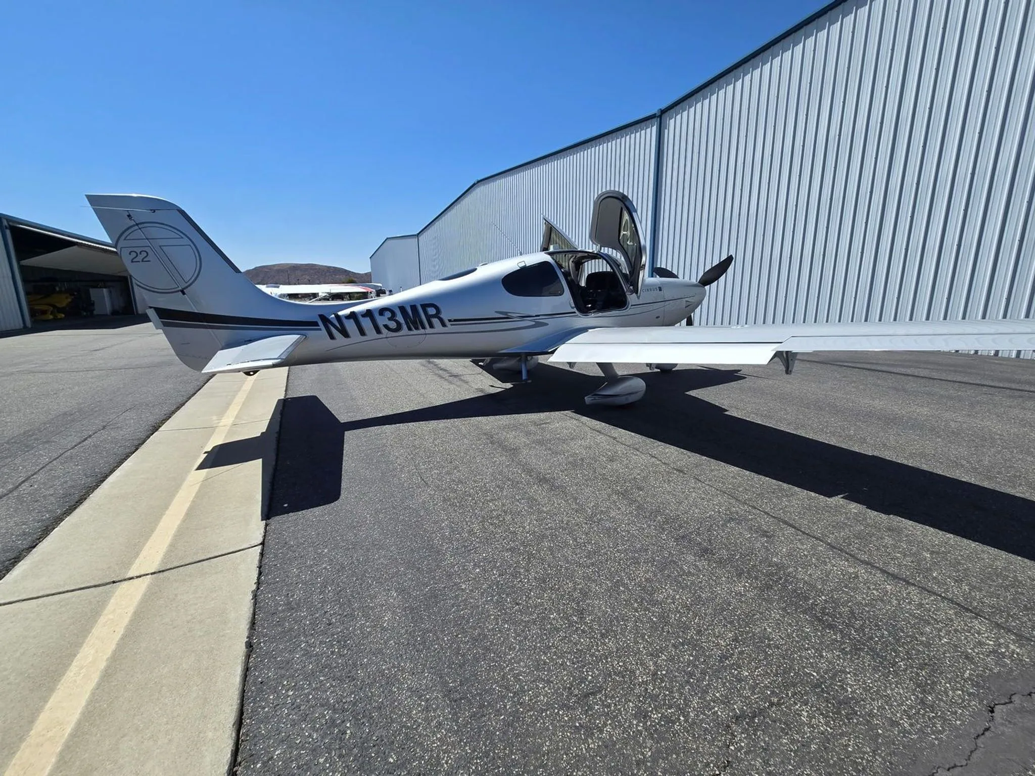


Free — save the SR22T to your watchlist and track it in one place.
More Cirrus SR22Tmanuals & documents
See all 21 →- Vantage 12 Pilot’s GuideV Speeds Reference
- Airworthiness Concern SheetAirworthiness Directives
- SERVICE BULLETIN HC-SB-30-390 Propeller - Spinner/Anti-ice Travel Tube InterferenceService Bulletins
- INSTRUCTIONS FOR INSTALLATION OF HARTZELL 4C1-F650A1/76C04(B)-0.6 PROPELLER ON CIRRUS SR22 AIRCRAFTMaintenance Manual
- INSTRUCTIONS FOR CONTINUED AIRWORTHINESS FOR HARTZELL 4C1-F650A1/76C04(B)-0.6 PROPELLER ON CIRRUS SR22T AIRCRAFTMaintenance Manual
- Supplemental Type Certificate SA03962ATSupplemental Type Certificate
- PILOT’S OPERATING HANDBOOK AND FAA APPROVED AIRPLANE FLIGHT MANUAL for the CIRRUS SR22Performance Data
- PILOT’S CHECKLIST SR22 G1 OR G2Checklist
- Continued Airworthiness Manual For Cirrus Design SR22 Series AirplanesMaintenance Manual
- Service Bulletin TAT SB10-01Service Bulletins
- Hartzell Engine Technologies Service Bulletin 033Service Bulletins
- SCHEDULE OF AIRWORTHINESS DIRECTIVESAirworthiness Directives
If you fly the Cirrus SR22T, you may also be researching these.




In this document
Introduction
The introduction outlines the purpose and scope of the manual, which is to provide detailed instructions for servicing and maintaining the air-conditioning system in the Cirrus SR22. It includes a glossary of terms and abbreviations used throughout the manual.
Air-conditioning System Description
This section describes the Keith Products vapor cycle air-conditioning system, which uses R134a refrigerant to cool the aircraft cabin. It details the major components, including the compressor, condenser, receiver/drier, expansion valve, and evaporator, along with their functions in the cooling process.
Troubleshooting
The troubleshooting section provides charts and procedures for diagnosing issues within the air-conditioning system. It includes common problems, their probable causes, and corrective actions, ensuring technicians can efficiently address system malfunctions.
Maintenance Procedures
This section outlines standard maintenance procedures for the air-conditioning system, including connection to components, o-ring replacement, and expansion valve removal and installation. It emphasizes the importance of using the correct lubricants and following safety precautions during maintenance.
System Servicing
The system servicing section details the procedures for discharging, evacuating, and charging the air-conditioning system. It specifies the use of R134a refrigerant and polyolester oil, along with the necessary tools and equipment for each task.
Safety notes
- Liquid R134a can freeze skin upon contact; handle with care.
- Always wear safety goggles when working with refrigerants.
- Refrigerant containers are under pressure; do not expose to heat or puncture.
Full document text
Products, Inc. Maintenance Manual with Illustrated Parts Catalog CR-220-10 Record of Revisions Page ii August 9, 2004 RECORD OF REVISIONS REV DATE DESCRIPTION BY APPV D 2/18/04 Added SL24002 to List of Service Bulletins; Added Paragraph 5 “Keith Products Kitting Structure” to Introduction; Updated List of Effective Pages; Section 21-50-01: Pg.2, Added “or 220-0251- 1” to Evaporator Assembly and “or 220-0670-1” to Pneumatic Assy, Pg. 101, Added “or 220-0251-1”, Pg. 102, Added “or 220-0670-1”, Pg. 103, Added “or 220-0251-1” to Evaporator Assembly and “or 220- 0670-1” to Pneumatic Assy, Pg. 108, Added “or 220- 0251-1”, Pg. 110, Added “or 220-0251-1” to Evaporator Assembly; Section 21-50-02: Pg. 1 & 201, Added “or 220- 0801”; Section 21-50-06: Pg. 3, Added “or 220- 0601”, Section 21-50-07: Pg. 102, Added to I/N 1 (-7 kit); Added Pgs. 103 & 104; Pg. 201, Added “220- 0301-1 Condenser Installation”; Pg. 202, Added to I/N 1 (-7 kit), and “or 220-0301-1” (-8 kit); Pg. 302, Added to I/N 1, (-7 & -8 kit); Revised I/N 2, was 220- 0450-1, now 220-0454-1; Pg. 401, Removed –2 & - 3; Pg. 402 was 220-0253-1, now 220-0263-1; Pg. 404, Added to I/N 1 (-7 kit), I/N 3, 220-1651-1 was (- 1 & -2 only), now (-14, -16, & -17 Trim Kit), I/N 3, 220-1654-1 was (-3 only), now (-15 Trim Kit), I/N 4, 220-1652-1 was (-1 & -2 only), now (-14, -16, & -17 Trim Kit), I/N 4, 220-1655-1 was (-3 only), now (-15 Trim Kit); Pg. 405, Added I/N 50; Added Pgs. 406 thru 409; Pg. 501, Removed 220-0700-4 & 220- 0700-5, Added 220-0701-1; Pg. 502, I/N 1, Removed -4 & -5, Added (-7 kit), 220-0701-1 (-8 kit); Pg. 503, Removed 220-1701-1, 220-1702-1, 220- 1703-1; Pg. 601, Added 220-0801-1, Added to I/N 1, (-7 kit), 220-0801-1 (-8 kit), Effective after S/N 820 Reason: New Fuselage Changes, per Project 23013 BCS/ LAW MAK Products, Inc. Maintenance Manual with Illustrated Parts Catalog CR-220-10 Record of Revisions Page iii June 6, 2006 REV DATE DESCRIPTION BY APPV E 08/09/04 Archived Rev. records NC - C, for previous revisions see Rev. D; Added SB192 & SB193 to list of Service Bulletins; Section 21-50-07: Pg. 102 I/N 3 was ES26105-1; Pg. 103 Deleted I/N 17 & I/N 18; Pg.104 I/N 3 was ES26105-1, I/N 7 was 220-0253-1, I/N 17 was 36-1650-27, I/N 18 was 220-1257-1; Pg. 301& 302 Added I/N’s 15 & 16; Pg. 402 Deleted I/N’s 30, 31, 33, 36 & 38; Added I/N 51; Pg. 403 Deleted I/N’s 37, 39, 42, 43, 44, 45, 46 & 48; Pg. 404 I/N 30 was ES53025-2, I/N 31 was ES53027-2, I/N 33 was ES48004-3, I/N 36 was ES30015-5, I/N 37 was ES55078-3; Pg. 405 I/N 38 was ES53027-3, I/N 39 was ES55078-4, I/N 42 was ES55078-1, I/N 43 was ES55078-2, I/N 44 was ES58161-15, I/N 45 was ES48060-3, I/N 46 was ES55078-5, I/N 48 was ES54145-20; Added I/N 51, Pg. 407 Updated View; Pg. 408 Deleted I/N 36; Pg. 409 I/N 22 was 220-1653-1, Pg. 602 I/N 4 was 220-0852-1. Reason: Dwg. Clarification per ER2490. MRR MAK F 02/27/06 Revised each schematic view Section 21-50-01: Pg. 2; Section 21-50-01: Pg. 110; Section 21-50-07: Pg. 501, pressure switch was connected to compressor now connected to firewall penetration. Section 21-50-07: Pg. 601, Revised view I/N’s 17, 18 was connected to I/N 3 now connected to I/N 13. Section 21-50-07: Pg 602 revised I/N 8 qty was 5 now 6 Section 21-50-07: Pg. 602 revised I/N 3 was 220-0856-1 qty 1 now 220-0862-1 qty 1 Add SB203 to List of Service Bulletins CDW MAK G 06/06/06 Added 220-0455-10 and MS20995C20 to Section 2 Tools and Equipment 21-50-03 Page 201 Added Section C Compressor drive shaft replacement to 21-50-03 Page 202 Added 220-0450-1, 220-0455-1 and 220-0455-10 to item number 2 on 21-50-07 page 302. Reason: Service Difficulty Per ER3201 LEO MAK Products, Inc. Maintenance Manual with Illustrated Parts Catalog CR-220-10 List of Service Bulletins Page v June 29, 2010 LIST OF SERVICE BULLETINS SB No. DATE SUBJECT REV DATE INCORP. SB190 1/6/04 A/C Switch Replacement Original SL24002 3/8/04 Service Letter, Compressor Drive Failure NC SB192 6/4/04 Expansion Valve Replacement NC SB193 6/24/04 Compressor Suction and Discharge Fittings NC SB203 2/22/06 Pressure Switch and Resistor Relocation NC Products, Inc. Maintenance Manual with Illustrated Parts Catalog CR-220-10 List of Effective Pages Page vi June 29, 2010 LIST OF EFFECTIVE PAGES CHAPTER SECTION SUBJECT PAGE DATE Title i June 29, 2010 Record Of Revisions ii August 9, 2004 iii June 6, 2006 iv June 29, 2010 List of Service Bulletins v June 29, 2010 List of Effective Pages vi June 29, 2010 vii June 29, 2010 viii June 29, 2010 Table of Contents ix June 29, 2010 Introduction x June 29, 2010 xi June 29, 2010 1 September 3, 2003 21-50-00 A/C System, System Description 2 September 3, 2003 3 September 3, 2003 Troubleshooting 101 May 20, 2003 102 May 20, 2003 103 May 20, 2003 104 May 20, 2003 Maintenance Procedures 201 October 27, 2003 202 October 27, 2003 System Servicing 301 May 20, 2003 302 October 27, 2003 303 October 27, 2003 304 June 29, 2010 305 June 29, 2010 306 June 29, 2010 Inspection/Check 601 May 20, 2003 602 October 27, 2003 Products, Inc. Maintenance Manual with Illustrated Parts Catalog CR-220-10 List of Effective Pages Page vii June 29, 2010 CHAPTER SECTION SUBJECT PAGE DATE 1 October 27, 2003 21-50-01 Electrical Description and Operation 2 June 5, 2008 Troubleshooting 101 February 18, 2004 102 February 18, 2004 103 February 18, 2004 104 January 6, 2004 105 June 29, 2010 106 June 29, 2010 107 June 29, 2010 108 June 29, 2010 109 October 27, 2003 110 June 29, 2010 21-50-02 Plumbing Description and Operation 1 February 27, 2006 Maintenance Practices 201 February 18, 2004 21-50-03 Compressor Description and Operation 1 September 3, 2003 Maintenance Practices 201 June 29, 2010 202 June 29, 2010 203 June 6, 2006 21-50-04 Condenser Description and Operation 1 May 20, 2003 Maintenance Practices 201 May 20, 2003 21-50-05 Evaporator Description and Operation 1 May 20, 2003
Show full textShow less
Maintenance Practices 201 May 20, 2003 21-50-06 Airworthiness Limitations 1 September 3, 2003 2 October 27, 2003 3 February 18, 2004 Products, Inc. Maintenance Manual with Illustrated Parts Catalog CR-220-10 List of Effective Pages Page viii June 29, 2010 CHAPTER SECTION SUBJECT PAGE DATE 21-50-07 Illustrated Parts Catalog 1 October 27, 2003 101 October 27, 2003 102 August 9, 2004 103 August 9, 2004 104 August 9, 2004 201 February 18, 2004 202 February 18, 2004 301 August 9, 2004 302 June 29, 2010 401 February 18, 2004 402 August 9, 2004 403 August 9, 2004 404 August 9, 2004 405 August 9, 2004 406 February 18, 2004 407 August 9, 2004 408 August 9, 2004 409 August 9, 2004 501 June 29, 2010 502 June 29, 2010 503 June 29, 2010 601 February 27, 2006 602 February 27, 2006 Products, Inc. Maintenance Manual with Illustrated Parts Catalog CR-220-10 Table of Contents Page ix June 29, 2010 TABLE OF CONTENTS SUBJECT SECTION PAGE Introduction ix Air-conditioning System 21-50-00 Description and Operation 1 Troubleshooting 101 Maintenance Practices 201 System Servicing 301 Inspection 601 Electrical 21-50-01 Description and Operation 1 Troubleshooting 101 Plumbing 21-50-02 Description and Operation 1 Maintenance Practices 201 Compressor 21-50-03 Description and Operation 1 Maintenance Practices 201 Condenser 21-50-04 Description and Operation 1 Maintenance Practices 201 Evaporator 21-50-05 Description and Operation 1 Maintenance Practices 201 Airworthiness Limitations Section 21-50-06 1 Illustrated Parts Catalogue 21-50-07 1 Products, Inc. Maintenance Manual with Illustrated Parts Catalog CR-220-10 Introduction Page x June 29, 2010 INTRODUCTION 1. PURPOSE The purpose of this System Service Manual is to provide detailed instructions for the servicing, troubleshooting, checking and maintaining of the Cirrus Design SR- 22 with Keith Products, Inc. air-conditioning system. The System Service Manual supplements the Maintenance Manual supplied by Cirrus Design for your particular aircraft. 2. SCOPE The scope of the System Service Manual provides the maintenance technician with detailed information covering: - Overall system level description and theory of operation. - Component level description and theory of operation. - System level checking and troubleshooting procedures. - Procedures for servicing the air-conditioning system refrigerant. - The identification of special equipment to accomplish the specific tasks. 3. GLOSSARY Nonstandard abbreviations and symbols used in the Maintenance Manual are described below. A/C - Air-conditioning A/R - As Required Assy - Assembly Comm. Avail. - Commercially Available Evap - Evaporator Gnd - Ground GPU - Ground Power Unit SW - Switch VDC - Volts Direct Current Products, Inc. Maintenance Manual with Illustrated Parts Catalog CR-220-10 Introduction Page xi June 29, 2010 4. MANUAL UPDATES To receive most up-to-date revisions of this manual, please visit www.keithproducts.com and click on PUBLICATIONS or call (972) 407-1234. 5. KEITH PRODUCTS KITTING STRUCTURE KIT SYSTEM DESCRIPTION EFFECTIVITY 220-0100-7 INSTALLATION KIT FOR SR22 PRE-S/N 820 220-0100-8 INSTALLATION KIT FOR SR22-G2 POST-S/N 820 KIT SYSTEM DESCRIPTION 11240-001 VOLS/AMP INDICATOR 220-0100-11 TRIM KIT FOR SR22-G2 WITH BLACK PANEL NOT INCLUDED 220-0100-12 TRIM KIT FOR SR22-G2 WITH SAND PANEL NOT INCLUDED 220-0100-13 TRIM KIT FOR SR22-G2 WITH ONYX PANEL NOT INCLUDED 220-0100-14 TRIM KIT FOR SR22 WITH AVIDYNE MFD & BLACK PANEL INCLUDED 220-0100-15 TRIM KIT FOR CENTENNIAL SR22 INCLUDED 220-0100-16 TRIM KIT FOR SR22 WITH ARNAV MFD INCLUDED 220-0100-17 TRIM KIT FOR SR22 WITH AVIDYNE MFD & BLACK PANEL NOT INCLUDED Products, Inc. Maintenance Manual with Illustrated Parts Catalog CR-220-10 21-50-00 Page 1 September 3, 2003 AIR-CONDITIONING SYSTEM SYSTEM DESCRIPTION 1. AIR-CONDITIONING SYSTEM DESCRIPTION The Keith Products vapor cycle air-conditioning system uses liquid refrigerant R134a to cool the aircraft cabin. The major components for the R134a air- conditioning system consist of a compressor, condenser, receiver/drier, expansion valve, and evaporator. The auxiliary drive pad located at the rear left side of the engine turns the compressor via a belt. Figure 1 shows an operational schematic of the air-conditioning system. The compressor takes the low-temperature, low-pressure gas and compresses it to a high-temperature, high-pressure gas. After the high-temperature, high-pressure gas leaves the compressor it enters the condenser. A 28 VDC blower forces air from an opening on the right hand side of the aircraft through the condenser. The air exits the condenser and leaves the aircraft through the exhaust duct underneath the baggage floor. This air cools the high-temperature, high-pressure gas as much as 100ºF. The gas is cooled until it condenses to a medium-temperature, high-pressure liquid. After the medium-temperature, high-pressure liquid leaves the condenser it enters the receiver/drier. The receiver/drier stores liquid refrigerant and filters any moisture out of the refrigerant. After the medium-temperature, high-pressure liquid leaves the receiver/drier it enters the expansion valve. The expansion valve allows the medium- temperature, high-pressure liquid to expand to a low-temperature, low-pressure spray of liquid. After the low-temperature, low-pressure spray of liquid leaves the expansion valve it enters the evaporator. A 28 VDC blower forces air from the cabin through the evaporator. Since the refrigerant in the evaporator can be as cold as 30ºF, the air from the cockpit causes the low-temperature, low-pressure liquid spray to boil and then evaporate. This low-temperature, low-pressure gas passes through the suction hose into the compressor. The refrigerant cycle continues, cooling the aircraft cabin. Air from the cabin is cooled as it passes through the evaporator and comes into contact with the refrigerant. Since the air is cooled, moisture from the air condenses in the evaporator and liquid water is formed. The water then drains overboard through the floor of the aircraft. Products, Inc. Maintenance Manual with Illustrated Parts Catalog CR-220-10 21-50-00 Page 2 September 3, 2003 Figure 1 Air-conditioning Vapor Cycle System Products, Inc. Maintenance Manual with Illustrated Parts Catalog CR-220-10 21-50-00 Page 3 September 3, 2003 2. SYSTEM OPERATION The air-conditioning system is operated with the engine operating and power supplied to the aircraft electrical system. To operate the system proceed as follows: 1) The system is off when the fan control knob is rotated to OFF. 2) To operate the cabin fan, rotate the fan control knob to LO, MED, or HI. 3) To operate the air-conditioning system, rotate the fan selector from the OFF position and push the pushbutton switch in. The green light in the switch will illuminate. The amount of airflow in the cabin can be varied by rotating the knob between LO, MED, and HI. 4) When air conditioning is selected the fresh air inlets, at the wing root/from the wing inlets, will close preventing outside air from entering the cabin. 5) For maximum cooling, place the FAN switch in the HI position, and open all air outlets. FAN CONTROL KNOB PUSHBUTTON SWITCH OFF Figure 2 Control Panel Products, Inc. Maintenance Manual with Illustrated Parts Catalog CR-220-10 21-50-00 Page 101 May 20, 2003 AIR-CONDITIONING SYSTEM TROUBLESHOOTING 1. GENERAL The procedures below present troubleshooting charts for the air-conditioning system and the compressor. A diagnoses chart is presented for insufficient air- conditioning system cooling. The performance of the air-conditioning system varies with ambient temperature and humidity. The information below presents possible air-conditioning system problems and solutions. CAUTION: Do not operate air-conditioning system with condenser air inlet or outlet blocked. 2. AIR-CONDITIONING SYSTEM DIAGNOSIS CHART The following pages show a procedure for diagnosing air-conditioning system problems that will expedite the troubleshooting process. Products, Inc. Maintenance Manual with Illustrated Parts Catalog CR-220-10 21-50-00 Page 102 May 20, 2003 CONDITION SERVICE PRESSURE GAUGE READING PROBABLE CAUSE CORRECTIVE ACTION INSUFFICIENT REFRIGERANT CHARGE Insufficient cooling. Bubbles appear in sight glass. SUCTION PRESSURE: below normal DISCHARGE PRESSURE: below normal Refrigerant is low or leaking. 1. Leak test. 2. Repair leak. 3. Charge system. Evacuate as necessary and recharge system. ALMOST NO REFRIGERANT No cooling action. A lot of bubbles or something like mist appears in sight glass. SUCTION PRESSURE: much below normal DISCHARGE PRESSURE: much below normal Serious refrigerant leak. Stop compressor immediately. 1. Leak test. 2. Discharge system. 3. Repair Leak(s). 4. Replace receiver/drier, if necessary. 5. Check oil level. 6. Evacuate and recharge system. FAULTY EXPANSION VALVE a) Slight cooling. Sweating or frosted expansion valve outlet. b) Insufficient cooling. Sweated suction line. c) No cooling. Sweating or frosted suction line. a) SUCTION PRESSURE: below normal DISCHARGE PRESSURE: below normal b) SUCTION PRESSURE: above normal DISCHARGE PRESSURE: below normal c) SUCTION PRESSURE: above normal DISCHARGE PRESSURE: below normal a) Expansion valve restricts refrigerant. Or, expansion valve is clogged. Or, expansion valve is inoperative. Or, valve stuck closed. Thermal bulb has lost charge. b) Expansion valve allows too much refrigerant through evaporator. Sensing bulb on suction line not well insulated or properly attached to line. c) Faulty expansion valve. a) Replace expansion valve. b) 1. Check valve for operation. If suction side does not show a pressure decrease, replace valve. 2. Check security and insulation on sensing bulb. c) 1. Discharge system. 2. Replace valve. 3. Evacuate and replace system. Products, Inc. Maintenance Manual with Illustrated Parts Catalog CR-220-10 21-50-00 Page 103 May 20, 2003 CONDITION SERVICE PRESSURE GAUGE READING PROBABLE CAUSE CORRECTIVE ACTION AIR IN SYSTEM Insufficient cooling. Sight glass shows occasional bubbles. SUCTION PRESSURE: above normal DISCHARGE PRESSURE: above normal Air mixed with refrigerant in system. Discharge system. Replace receiver/drier. Evacuate and charge system. MOISTURE IN SYSTEM After operation for a while, pressure on suction side may show vacuum pressure reading. During this condition, discharge air will be warm. As warning of this, reading shows approx. 6 psi oscillation. SUCTION PRESSURE: below normal DISCHARGE PRESSURE: above normal Drier is saturated with moisture. Moisture has frozen at expansion valve. Refrigerant flow is restricted. 1. Discharge system. 2. Replace receiver/ drier (twice if necessary). 3. Evacuate system completely. (Repeat 30 minute evacuating three times.) 4. Recharge system. FAULTY CONDENSER Insufficient cooling. Bubbles appear in sight glass of drier. Suction line is very hot. SUCTION PRESSURE: above normal DISCHARGE PRESSURE: above normal Condenser air or refrigerant flow is restricted. Check condenser for dirt accumulation or bent fins. Clean/ replace as necessary. Check for refrigerant overcharge. If pressure remains high in spite of all above actions taken, remove and inspect the condenser for possible oil clogging. HIGH PRESSURE LINE BLOCKED Insufficient cooling. Frosted high pressure liquid line. SUCTION PRESSURE: much below normal DISCHARGE PRESSURE: much above normal Drier clogged, or restriction in high pressure line. Discharge system. Replace receiver/drier. Evacuate and charge system Products, Inc. Maintenance Manual with Illustrated Parts Catalog CR-220-10 21-50-00 Page 104 May 20, 2003 CONDITION SERVICE PRESSURE GAUGE READING PROBABLE CAUSE CORRECTIVE ACTION FAULTY COMPRESSOR Insufficient cooling. Rough running. SUCTION PRESSURE: much below normal DISCHARGE PRESSURE: much above normal N/A Internal problem in compressor, or damaged gasket and valve. Internal problem with compressor body. Discharge system. Remove and check compressor. Repair or replace compressor. Check oil level. Replace receiver/ drier. Evacuate and charge system. Replace compressor. TOO MUCH OIL IN SYSTEM (Excessive) Insufficient cooling. SUCTION PRESSURE: above normal DISCHARGE PRESSURE: above normal Too much oil circulates with refrigerant, causing the cooling capacity of the system to be reduced. Refer to Oil Level Check for correcting oil level. WATER BEING BLOWN OUT OF EVAPORATOR SUCTION PRESSURE: normal DISCHARGE PRESSURE: normal Blocked evaporator drain. Check evaporator drain for downhill routing and repair any kinks or blockage in drain tubing. Products, Inc. Maintenance Manual with Illustrated Parts Catalog CR-220-10 21-50-00 Page 201 October 27, 2003 AIR-CONDITIONING SYSTEM MAINTENANCE PROCEDURES 1. General The following procedures are used to perform typical maintenance on the air- conditioning system plumbing. Procedures are provided for making connections to components, and replacing the expansion valve. Keith Products air-conditioning systems use swaged hose fittings with "o-ring" type connections. 2. Tools and Equipment Designation Ref. No. Qty Remarks Polyolester Oil Comm. Avail. A/R Viscosity ISO 68 Sealant ES49000-1 A/R Available from Keith Products 3. Connection to Components - O-Ring Replacement 1) Place the appropriate o-ring over the tube "O" end of the fitting. 2) Lubricate o-ring with polyolester oil viscosity ISO 68 or ES49000-1 sealant prior to assembly. 4. Expansion Valve Removal and Installation The following procedure is used to remove or install the air-conditioning system expansion valve, located on the inlet side of the evaporator coil. 1) Discharge system in accordance with instructions included in this manual. 2) Disconnect and cap the liquid hose from the expansion valve inlet. 3) Remove the insulation covering the thermal sense bulb on the suction tubing. 4) Cut the tie wraps binding the sense bulb to the suction tubing. 5) Disconnect externally equalized port & discard o-ring. 6) Disconnect the fitting that connects the expansion valve to the coil, and remove the expansion valve. Discard the old expansion valve and o-ring. 7) Install new ES26105-1 expansion valve and ES49011–2 o-ring. Lubricate o-ring with polyolester oil viscosity grade ISO 68 or ES49000-1 sealant. 8) Install the thermal sense bulb such that it makes contact with the suction tube along its entire length with two or more cable ties as shown in Figure 3. 9) Insulate the bulb thoroughly with insulation to suction tubing. Products, Inc. Maintenance Manual with Illustrated Parts Catalog CR-220-10 21-50-00 Page 202 October 27, 2003 10) Attach externally equalized port using an ES49022-4 o-ring, lubricate o-ring with ES49000-1 sealant or polyolester oil viscosity grade (ISO) 68. NOTE: Always use two wrenches to not twist or bend the lines. Figure 3 Correct expansion valve and sense bulb orientation Products, Inc. Maintenance Manual with Illustrated Parts Catalog CR-220-10 21-50-00 Page 301 May 20, 2003 AIR-CONDITIONING SYSTEM SYSTEM SERVICING 1. GENERAL The air-conditioning system uses refrigerant R134a and the compressor lubricating oil used is Polyolester Oil viscosity grade (ISO) 68. No other refrigerant or compressor oil should be used. Refrigerant R134a is non-explosive, non-flammable, non-corrosive, has practically no odor, and is heavier than air. Although R134a is classified as a safe refrigerant, certain precautions must be observed to personnel and property when working with R134a refrigerant. WARNING: A. Liquid R134a, at normal atmospheric pressure and temperature, evaporates so quickly that it tends to freeze anything that it contacts. Care must be taken to prevent any liquid refrigerant from coming into contact with skin. B. Always wear safety goggles when servicing any part of the refrigerant system to prevent refrigerant from coming into contact with the eyes. C. The refrigerant containers and the air-conditioning components are under pressure. Do not expose the air-conditioning system or refrigerant containers to heat. Do not puncture the air-conditioning components or the refrigerant containers. CAUTION: Do not operate air-conditioning system with condenser air inlet or outlet blocked. 2. DISCHARGING SYSTEM A. General The air-conditioning system refrigerant must be discharged prior to disconnecting or removing any components in the refrigerant loop. Federal law prohibits discharging refrigerant into the atmosphere. Use only an R134a compatible recycling/recovery unit when discharging the air-conditioning system. Products, Inc. Maintenance Manual with Illustrated Parts Catalog CR-220-10 21-50-00 Page 302 October 27, 2003 B. Tools and Equipment Designation Ref. No. Qty Remarks R134a Compatible Recycling/Recovery Unit Comm. Avail. 1 None C. Discharging Procedure 1) Connect R134a compatible recycling/recovery unit to the R134a service valves located forward of the firewall. 2) Empty the recycling/recovery unit of oil. 3) Discharge the air-conditioning system in accordance with the recovery unit's instructions. 4) Empty the oil from the recycling/recovery unit. Note the amount of oil removed during the system discharge. This amount of oil must be added to the air-conditioning system prior to charging. Only use polyolester oil viscosity grade ISO 68. 3. EVACUATING SYSTEM A. General The air-conditioning system must be evacuated prior to charging the system with refrigerant. Evacuating the system removes any moisture and air that may be in the system. Use only an R134a compatible recycling/recovery unit when evacuating the air-conditioning system. B. Tools and Equipment Designation Ref. No. Qty Remarks R134a Compatible Recycling/Recovery Unit Comm. Avail. 1 None Products, Inc. Maintenance Manual with Illustrated Parts Catalog CR-220-10 21-50-00 Page 303 October 27, 2003 C. Evacuating Procedure 1) Connect R134a compatible recycling/recovery unit to the R134a service valves on the aircraft's air-conditioning system. 2) Empty the oil from the recycling/recovery unit. 3) Evacuate the air-conditioning system in accordance with the recovery unit's instructions for a minimum of 15 minutes. 4) Empty the oil from the recycling/recovery unit. Note the amount of oil removed during the vacuum. This amount of oil must be added to the air- conditioning system prior to charging. Only use polyolester oil viscosity grade ISO 68. 5) Once the air-conditioning system has been evacuated, it is then ready for charging with new/recycled R134a refrigerant. 4. CHARGING SYSTEM A. General Use only R134a refrigerant when charging the air-conditioning system. Federal law prohibits discharging refrigerant into the atmosphere. Use only R134a compatible recycling/recovery unit when charging the air-conditioning system. B. Tools and Equipment Designation Ref. No. Qty Remarks R134a Compatible Recycling/Recovery Unit and Pressure Gauges Comm. Avail. 1 None R134a refrigerant Comm. Avail. 2.0 lbs. None Polyolester Oil Comm. Avail. 5 fl. oz. Viscosity ISO 68 C. Charging Procedure 1) Connect R134a compatible recycling/recovery unit to the R134a service valves on the aircraft's air-conditioning system. If recovery unit does not have pressure gauges, connect service pressure gauges to air- conditioning system. 2) Evacuate the air-conditioning system for 15 minutes in accordance with the instructions in this report. 3) Close the low side and open the high side on the recycling/recovery unit. 4) Add polyolester oil viscosity ISO 68 to the high side service tee using the refrigerant recycling/recovery unit while the system is under a vacuum. Products, Inc. Maintenance Manual with Illustrated Parts Catalog CR-220-10 21-50-00 Page 304 June 29, 2010 NOTE: Adding refrigerant or oil from the recycling/recovery unit directly to the low-pressure service tee will allow liquid refrigerant or oil to enter the compressor. The compressor is only designed to compress gas refrigerant, and liquid refrigerant or oil may damage/destroy the compressor. Always close the low side of the recycling/recovery unit during charging. 5) Charge the air-conditioning system in accordance with the recovery unit's instructions except as noted. If bubbles are present at the sight glass after the system has been running for a minimum of 5 minutes, add refrigerant as necessary. FLUSHING SYSTEM A. General The following procedure is used to whenever the compressor is replaced and when system contamination is suspected. B. Tools and Equipment Designation Ref. No. Qty Remarks Keith Hose Coupler Tool JBS6009-1 JBS6020-7 JBS6020-8 JBS6020-3 1 1 1 1 None Service Pressure Gauge Comm. Avail. 1 None R134a Compatible Recycling/Recovery Unit Comm. Avail. 1 None Polyolester Oil Comm. Avail. A/R Viscosity ISO 68 1. System Flushing Procedure 1. Connect the refrigerant recovery cart to the normal service ports. 2. Empty the refrigerant recovery cart’s oil collection tube so that it begins with zero oil collected. 3. Discharge the air-conditioning system and recover the refrigerant per the refrigerant cart’s instructions. Do not empty the oil collection tube. 4. Disconnect the refrigerant recovery cart from the normal service ports. Products, Inc. Maintenance Manual with Illustrated Parts Catalog CR-220-10 21-50-00 Page 305 June 29, 2010 5. Remove the compressor and connect the service valve couplers P/N’S JBS6020-7 and JBS6020-8 to the suction and discharge plumbing hoses. 6. Bypass the binary pressure switch, by connecting the hose assembly directly to the firewall bulkhead fitting. 7. Remove the receiver/drier bottle from the aircraft and properly dispose. Attach the hose coupler tool p/n JBS6009-1 in place of the receiver/drier bottle. 8. Disconnect all of the expansion valves from the evaporator assemblies. Attach the hose coupler tool P/N JBS6020-3 in place of the expansion valves on all evaporator assemblies. Use caution in handling the expansion valves. Do no support the expansion valve by its remote bulb tubing. Do not disconnect the external equalization port fitting. 9. Connect the refrigerant recovery cart to the service port couplers located where the compressor was removed to create a refrigerant loop with the refrigerant cart. 10. Evacuate the system thru the HIGH side port only per the refrigerant recovery cart’s instructions for a minimum 10 minutes. 11. Charge the system thru the LOW side port only with 1.5 to 2 times a normal refrigerant charge of refrigerant. Do not add any oil to system. 12. Discharge the system thru the HIGH side port only per the refrigerant recovery cart’s instructions. 13. Repeat previous three steps two additional times. 14. Disconnect the refrigerant recovery cart from the service ports. 15. Remove the compressor and drain all of the oil from the compressor into an empty graduated cylinder. It will be necessary to rotate the clutch plate several times to get as much oil as possible from the compressor. 16. Empty the refrigerant recovery cart’s oil collection tube into the graduated cylinder with the drained compressor oil. Inspect the oil for debris contamination and replace compressor if necessary. 17. New compressors come serviced with 5 ounces of oil and do not require oil adjustment. If the existing removed compressor is reused or other Products, Inc. Maintenance Manual with Illustrated Parts Catalog CR-220-10 21-50-00 Page 306 June 29, 2010 replacement compressor for which the oil level is unknown, then completely drain the compressor and then add 5 ounces of new polyolester oil ISO grade 68 to the compressor. Torque the oil plug to 6 to 9 ft-lbs. 18. Install the compressor. Use new o-rings. 19. Inspect the expansion valves for damage and debris. Replace if any contamination is found. Use new o-rings. 20. Inspect the binary pressure switch for damage and debris. Flush with dry nitrogen or clean dry compressed air before re-installing. Use new o-rings. 21. Install a new receiver/drier bottle. Do not reuse the old bottle under any circumstance. Use new o-rings. Caution: Receiver/drier bottles left open to the atmosphere for more than 10 minutes must be discarded and replaced with new. 22. Evacuate the system per the refrigerant recovery cart’s instructions for a minimum 15 minutes. 23. Add 2 ounces of new polyolester oil ISO grade 68 to the system thru the HIGH side port only. 24. Charge the system per Charging Procedure step 3. Products, Inc. Maintenance Manual with Illustrated Parts Catalog CR-220-10 21-50-00 Page 601 May 20, 2003 AIR-CONDITIONING SYSTEM INSPECTION/CHECKS 1. GENERAL General service procedures are provided to keep the air-conditioning system operating at peak efficiency. Procedures are provided for inspection intervals, refrigerant charge inspection, refrigerant leak inspection, and compressor oil level inspection. CAUTION: Do not operate air-conditioning system with condenser air inlet or outlet blocked. A. Tools and Equipment Designation Ref. No. Qty Remarks Service Pressure Gage Comm. Avail. 1 None Electronic Leak Detector Comm. Avail. A/R R134a Compatible Polyolester Oil Comm. Avail. A/R Viscosity ISO 68 2. INSPECTION INTERVALS See Section 21-50–06: Airworthiness Limitations for inspection intervals. 3. REFRIGERANT LEVEL INSPECTION To be performed when improper refrigerant charge is suspected. A. With the engine running, turn the air-conditioning system ON by rotating the fan switch to the high setting and pushing the pushbutton switch in. The green light will illuminate. B. Run system for five (5) minutes minimum. C. Check that the receiver/drier inlet and outlet fitting temperatures are the same. If the outlet is considerably colder, the receiver/drier screen may be clogged and may need replacement. D. Check the sight glass for bubbles. No bubbles should be visible after 5 minutes of operation. Products, Inc. Maintenance Manual with Illustrated Parts Catalog CR-220-10 21-50-00 Page 602 October 27, 2003 NOTE: The refrigerant bubbles are more difficult to see at ambient temperatures below 65ºF. Always re-check refrigerant level when ambient temperature is above 65ºF for proper level. E. Add/remove refrigerant as necessary. 4. REFRIGERANT SYSTEM LEAKAGE INSPECTION To be performed when refrigerant leak is suspected. A. The system leakage check is to be performed in an area with an ambient temperature of 65ºF or above. B. Install service pressure gage onto low and high pressure R134a service valves. C. On systems that have not been operated for 2 weeks or longer, operate the system for a minimum of 10 minutes. This will lubricate the compressor shaft seal and ensure a more accurate leakage check of the shaft seal. D. With the system off and using the electronic leak detector, check all connections, compressor shaft seal, and fabricated components for leakage. No leakage is acceptable. 5. COMPRESSOR OIL LEVEL CHECK NOTE: It is not necessary to check the compressor oil level during routine maintenance. It only needs to be checked when a system component is replaced or when incorrect oil level is suspected. Only polyolester oil viscosity grade ISO 68 should be used. 1) Operate air-conditioning system for 10 minutes. This will collect as much oil as possible in the compressor. 2) Discharge air-conditioning system in accordance with the discharging instructions in this manual. 3) Remove compressor from the aircraft and cap the hose fittings. 4) Remove oil drain plug and allow all oil to drain. 5) Add 3 ounces of oil to the compressor. 6) Clean oil drain area and install drain plug. Torque to 6 - 9 ft-lbs. 7) Re-install the compressor and reconnect the hose fittings. 8) Draw a vacuum onto the system. While system is under a vacuum add 2 oz. of oil to the discharge line. 9) Charge air-conditioning system in accordance with the charging instructions in this manual. Products, Inc. Maintenance Manual with Illustrated Parts Catalog CR-220-10 21-50-01 Page 1 October 27, 2003 ELECTRICAL DESCRIPTION AND OPERATION 1. GENERAL The electrical system of the Cirrus Design SR22 air-conditioning system operates from the main 28 VDC buss. The major components of the electrical system are: Evaporator/Blower: Re-circulates cold air into the cabin. Condenser/Blower: Removes heat from the refrigerant. Compressor Clutch: Engages/disengages the compressor. Switches: Control the operation mode of the system Pneumatic pump: Inflates the duct sealing bladders 2. SAFETY FEATURES Before electrical current reaches the compressor clutch it passes through the JBS2020-7 Pressure Switch and the JBS60-2 Freeze Switch. In the event of excessive refrigerant pressure during flight (caused by failed or blocked condenser blower) or inadequate refrigerant pressure (caused by a leak in the plumbing) the JBS2020-7 pressure switch will open and disable the compressor clutch. In the event of extremely low temperature air exiting the evaporator (which may cause the coil to freeze) the JBS60-2 Freeze Switch will open and disable the compressor clutch. Products, Inc. Maintenance Manual with Illustrated Parts Catalog CR-220-10 21-50-01 Page 2 June 29, 2010 Products, Inc. Maintenance Manual with Illustrated Parts Catalog CR-220-10 21-50-01 Page 101 February 18, 2004 ELECTRICAL TROUBLESHOOTING 1. GENERAL The following procedures are used for troubleshooting the electrical system and the electrical interface with the other assemblies of the air-conditioning system. The procedures systematically check every reasonable cause of the failure, starting from the power source that might result in the inoperation of the evaporator blower, condenser blower, and compressor clutch. If the problem causing the component to fail is suspected, the suspected cause should be checked first. The sequence of checks may be varied to increase the convenience of the checker as desired. A. TOOLS AND EQUIPMENT DESIGNATION REF. NO. QTY. REMARKS Service pressure gauge Comm. Avail 1 None Multi-meter Comm. Avail 1 None 28 VDC source A/R None 2. Evaporator Blower Does Not Operate 1) Turn the air conditioning system off. The A/C switch will be in the OFF position and the fan control knob rotated to the OFF position. 2) With the engine inoperative, turn on the battery power. 3) Disconnect the ES53026-1 electrical connector to the 220-0250-1 or 220-0251-1 evaporator/ blower assembly. 4) Check for a ground connection at Pin 6. 5) If no ground is present then check and replace/repair the down stream electrical connections and/or wires. 6) If the ground is present at Pin 6 then rotate the fan control knob to LO and check for power at Pin 3. The terminal should have a voltage reading between 26.0V and 29.0V. Use Pin 6 as the ground when checking the power. 7) Repeat previous step checking Pin 4 with the fan switched to MED and Pin 5 with the fan switched to HI. 8) If correct power is present at Pin 3 (when switched to LO), Pin 4 (when switched to MED), and Pin 5 (when switched to HI) then replace/repair the 220-0250-1 or 220-0251-1 evaporator/blower assembly. Products, Inc. Maintenance Manual with Illustrated Parts Catalog CR-220-10 21-50-01 Page 102 February 18, 2004 9) If power is not present at Pin 3, 4, and 5 then reconnect the evaporator/blower assembly connector. 10) Check for power at the 15A circuit breaker labeled “cabin blower” and 2A circuit breaker labeled “air cond”. The terminals should have a voltage reading between 26.0V and 29.0V. Use a suitable aircraft ground when checking for power. 11) If power is not present then check and replace/repair the circuit breaker and/or up stream electrical connections and/or wires. 12) If power is present then disconnect the ES53026-2 connector to the 220-0653-1 or 220-0670-1 pneumatic assembly. 13) Check for 26-29v connection at pin 6, 7, & 8 when the rotary switch is in the LO, MED, & HI positions respectively. 14) If power is present then check and replace/repair the electrical connections and/or wires between the evaporator/blower assembly and pneumatic assembly. 15) Check for a ground connection at Pin 9. 16) If no ground is present then check and replace/repair the down stream electrical connections and/or wires. 17) If the ground is present then rotate the fan control knob to LO and check for power at Pin 4. The terminal should have a voltage reading between 26.0V and 29.0V. Use Pin 9 as the ground when checking the power. 18) Repeat previous step checking Pin 3 with the fan switched to MED, Pin 2 with the fan switched to HI, and Pin 1 with the fan switched to any position. 19) If correct power is present at Pin 4 (when switched to LO), Pin 3 (when switched to MED), Pin 2 (when switched to HI), and Pin 1 then replace/repair the 220-0653-1 or 220-0670-1 pneumatic assembly. 20) If power is not present at Pin 1 then check and replace/repair the up stream electrical connections and/or wires. 21) If power is not present at Pin 2, 3, and 4 then reconnect the pneumatic assembly connector. 22) Check for power at Pin C1 of the ES57117-1 rotary switch. The terminal should have a voltage reading between 26.0V and 29.0V. Use a suitable aircraft ground when checking for power. 23) If power is not present then check and replace/repair the up stream electrical connections and/or wires. 24) If power is present then rotate the fan control knob to LO and check for power at Pin 2. The terminal should have a voltage reading between 26.0V and 29.0V. Use a suitable aircraft ground when checking for power. 25) Repeat previous step checking Pin 3 with the fan switched to MED, and Pin 4 with the fan switched to HI. 26) If power is present at Pin 2 (when switched to LO), Pin 3 (when switched to MED), Pin 4 (when switched to HI) then check and replace/repair the electrical connections and/or wires between the rotary switch and pneumatic assembly. 27) If power is not present at Pin 2, 3, and 4 then replace/repair the ES57117-1 rotary switch. Products, Inc. Maintenance Manual with Illustrated Parts Catalog CR-220-10 21-50-01 Page 103 February 18, 2004 Evaporator Blower Electrical Schematic FOR REF. ONLY Products, Inc. Maintenance Manual with Illustrated Parts Catalog CR-220-10 21-50-01 Page 104 January 6, 2004 3. Condenser Blower Doesn’t Operate 1) Turn the air conditioning system off. The A/C switch will be in the OFF position and the fan control knob rotated to the OFF position. 2) With the engine inoperative, turn on the battery power. 3) Disconnect the ES55148-1 electrical connector to the 220-0351-1 fan assembly. 4) Check for a ground connection at Pin 1. 5) If no ground is present then check and replace/repair the down stream electrical connections and/or wires. 6) If the ground is present at Pin 1 then rotate the fan control knob to LO, MED, or HI and push the a/c switch to ON. 7) Check for power at Pin 2. The terminal should have a voltage reading between 26.0V and 29.0V. Use Pin 1 as the ground when checking the power. 8) If correct power is present at Pin 2 then replace/repair the 220-0351-1 fan assembly. 9) If power is not present at Pin 2 then reconnect the fan assembly connector. 10) Check for power at the 15A circuit breaker labeled “cond fan” and 2A circuit breaker labeled “air cond”. The terminals should have a voltage reading between 26.0V and 29.0V. Use a suitable aircraft ground when checking for power. 11) If power is not present then check and replace/repair the circuit breaker and/or up stream electrical connections and/or wires. 12) If power is present then check for power at Pin C1 and Pin C7 of the ES57117- 1 rotary switch. The terminal should have a voltage reading between 26.0V and 29.0V. Use a suitable aircraft ground when checking for power. 13) If power is not present then check and replace/repair the up stream electrical connections and/or wires. 14) If power is present then rotate the fan control knob to LO and check for power at Pin 8. The terminal should have a voltage reading between 26.0V and 29.0V. Use a suitable aircraft ground when checking for power. 15) Repeat previous step checking Pin 9 with the fan switched to MED, and Pin 10 with the fan switched to HI. 16) If power is not present at Pin 8 (when switched to LO), Pin 9 (when switched to MED), Pin 10 (when switched to HI) then replace/repair the ES57117-1 rotary switch. 17) If power is present at Pin 8, 9, and 10 then disconnect the ES53011-1 electrical connector to the 220-0753-1 switch assembly. 18) Check for continuity between Pin 2 and Pin 3 of the switch assembly with the switch in the ON position. 19) If the connection is open then replace/repair the 220-0753-1 switch assembly. Products, Inc. Maintenance Manual with Illustrated Parts Catalog CR-220-10 21-50-01 Page 105 June 29, 2010 20) If the connection is closed then check for a ground connection at Pin 5 of ES56128-2. (or Pin 5 of JBS1105-1 relay assembly) 21) If no ground is present then check and replace/repair the down stream electrical connections and/or wires. 22) If a ground is present then check for continuity between Pin 4 and Pin 5 of ES56128-2. (or Pin 4 and Pin 5 of JBS1105-1 relay assembly) 23) If the connection is open then replace/repair the ES56128-2. (or JBS1105-1 relay assembly) 24) If the connection is closed then check for a ground connection at Pin 3 of the ES53011-1 connector to the switch assembly. 25) If no ground is present then check and replace/repair the electrical connections and/or wires between the connector and relay. 26) If a ground is present then check for power at Pin 2 of the ES53011-1 connector. The terminal should have a voltage reading between 26.0V and 29.0V. Use Pin 3 as the ground when checking the power. 27) If power is not present at Pin 2 of the connector then check and replace/repair the electrical connections and/or wires between the connector and rotary switch. 28) If power is present at Pin 2 of the connector then reconnect the switch assembly. 29) Check for power at Pin 3 of ES56128-2. (or Pin COM of JBS1105-1 relay assembly) The terminal should have a voltage reading between 26.0V and 29.0V. Use Pin 5 of ES56128-2 (or Pin 5 of JBS1105-1 relay assembly) as a ground when checking the power. 30) If power is not present then check and replace/repair the up stream electrical connections and/or wires. 31) If power is present then check for power at Pin 1 of ES56128-2. (or Pin NO of JBS1105-1 relay assembly) Be sure that both the a/c and fan switches are on. The terminal should have a voltage reading between 26.0V and 29.0V. Use a Pin 5 of the relay as a ground when checking the power. 32) If power is not present then check and replace/repair the electrical connections and/or wires between the relay and condenser fan. Products, Inc. Maintenance Manual with Illustrated Parts Catalog CR-220-10 21-50-01 Page 106 June 29, 2010 Condenser Electrical Schematic FOR REF. ONLY Products, Inc. Maintenance Manual with Illustrated Parts Catalog CR-220-10 21-50-01 Page 107 June 29, 2010 4. Compressor Clutch Doesn’t Engage NOTE: If the ambient temperature is less than 45ºF the freeze switch may disable the compressor clutch. In order to troubleshoot an inoperative compressor clutch at temperatures less than 45ºF, use a short wire as a jumper between Pin 1 and Pin 2 of the ES53026-1 Electrical Connector that connects to the evaporator assembly. This will bypass the freeze switch. 1) With the engine inoperative, turn on the battery power. 2) Turn the air conditioning system on. The A/C switch will be in the ON position and the fan control knob rotated to the LO, MED, or HI position. 3) Check for power at positive terminal of the compressor clutch. The terminal should have a voltage reading between 24.0V and 29.0V. Use a suitable aircraft ground when checking the power. 4) If correct power is present and the clutch does not engage (the coil does not magnetize) then replace/repair the 220-0451-1 compressor assembly. 5) If power is not present then check for power at the 15A circuit breaker labeled “cond fan” and 2A circuit breaker labeled “air cond”. The terminals should have a voltage reading between 26.0V and 29.0V. Use a suitable aircraft ground when checking for power. 6) If power is not present then check and replace/repair the circuit breaker and/or up stream electrical connections and/or wires. 7) If power is present then check for a ground connection at Pin 5 of ES56128-2 or Pin 5 of JBS1105-1 relay assembly. 8) If no ground is present then check and replace/repair the down stream electrical connections and/or wires. 9) If a ground is present then check for power at Pin 3 of ES56128-2 or Pin COM of JBS1105-1 relay assembly. The terminal should have a voltage reading between 26.0V and 29.0V. Use Pin 5 of ES56128-2 or Pin 5 of JBS1105-1 relay assembly as a ground when checking the power. 10) If power is not present then check and replace/repair the up stream electrical connections and/or wires. 11) If power is present then check for power at Pin 1 of ES56128-2 or Pin NO of JBS1105-1 relay assembly. The terminal should have a voltage reading between 26.0V and 29.0V. Use Pin 5 of ES56128-2 or Pin 5 of JBS1105-1 relay assembly as a ground when checking the power. 12) If power is present then proceed to step 28. 13) If power is not present then check for power at Pin C1 and Pin C7 of the ES57117-1 rotary switch. The terminal should have a voltage reading between 26.0V and 29.0V. Use a suitable aircraft ground when checking for power. 14) If power is not present then check and replace/repair the up stream electrical connections and/or wires. Products, Inc. Maintenance Manual with Illustrated Parts Catalog CR-220-10 21-50-01 Page 108 June 29, 2010 15) If power is present then rotate the fan control knob to LO and check for power at Pin 8. The terminal should have a voltage reading between 26.0V and 29.0V. Use a suitable aircraft ground when checking for power. 16) Repeat previous step checking Pin 9 with the fan switched to MED, and Pin 10 with the fan switched to HI. 17) If power is not present at Pin 8 (when switched to LO), Pin 9 (when switched to MED), Pin 10 (when switched to HI) then replace/repair the ES57117-1 rotary switch. 18) If power is present at Pin 8, 9, and 10 then disconnect the ES53011-1 electrical connector to the 220-0753-1 switch assembly. 19) Check for continuity between Pin 2 and Pin 3 of the switch assembly with the switch in the ON position. 20) If the connection is open then replace/repair the 220-0753-1 switch assembly. 21) If the connection is closed then check for continuity between Pin 4 and Pin 5 of ES56128-2 or Pin 1 and Pin 3 of ES56161-1 relay. 22) If the connection is open then replace/repair the ES56128-2 or ES56161-1 relay. 23) If the connection is closed then check for a ground connection at Pin 3 of the ES53011-1 connector to the switch assembly. 24) If no ground is present then check and replace/repair the electrical connections and/or wires between the connector and relay. 25) If a ground is present then check for power at Pin 2 of the ES53011-1 connector. The terminal should have a voltage reading between 26.0V and 29.0V. Use Pin 3 as the ground when checking the power. 26) If power is not present at Pin 2 of the connector then check and replace/repair the electrical connections and/or wires between the connector and rotary switch. 27) If power is present at Pin 2 of the connector then reconnect the switch assembly. 28) Disconnect the ES53026-1 electrical connector to the evaporator/blower assembly and check for power at Pin 2 of the connector. The terminal should have a voltage reading between 26.0V and 29.0V. Use Pin 6 as the ground when checking the power. 29) If power is not present then check and replace/repair the KAC220-12-16 wire and/or electrical connections. 30) If power is present then check for continuity between Pin 1 and Pin 2 of the evaporator/blower assembly. This check requires the ambient temperature to be above 45ºF. 31) If the connection is open then replace/repair the 220-0250-1 or 220-0251-1 evaporator/blower assembly. 32) If the connection is closed then reconnect the ES53026-1 connector and disconnect the ES53033-1 electrical connector to the JBS2020-7 pressure switch and check for power at Pin 1 of the connector. The terminal should have a voltage reading between 26.0V and 29.0V. Use a suitable aircraft ground when checking the power. Products, Inc. Maintenance Manual with Illustrated Parts Catalog CR-220-10 21-50-01 Page 109 October 27, 2003 33) If power is not present then check and replace/repair the KAC220-22-16 wire and/or electrical connections. 34) If power is present then check for continuity between Pin 1 and Pin 3 of the pressure switch. 35) If the connection is open then check the refrigerant pressure. If the pressure is less than 35 PSIG or greater than 340 PSIG then add/remove refrigerant to the proper level and recheck pressure switch. If switch connection is still open then replace/repair the JBS2020-7 pressure switch. 36) If the connection is closed then reconnect the ES53033-1 connector and check for power at the positive terminal of the ES63014-16 resistor. The terminal should have a voltage reading between 26.0V and 29.0V. Use a suitable aircraft ground when checking the power. 37) If power is not present then check and replace/repair the KAC220-23-16 wire and/or electrical connections. 38) If power is present then check for power at the negative terminal of the ES63014-16 resistor. The terminal should have a voltage reading between 10-16v. Use a suitable aircraft ground when checking the power. 39) If power is not present then check and replace/repair the ES63014-16 resistor. Products, Inc. Maintenance Manual with Illustrated Parts Catalog CR-220-10 21-50-01 Page 110 June 29, 2010 Compressor Clutch Electrical Schematic FOR REF. ONLY Products, Inc. Maintenance Manual with Illustrated Parts Catalog CR-220-10 21-50-02 Page 1 February 27, 2006 PLUMBING DESCRIPTION AND OPERATION 1. GENERAL The plumbing system consists of flexible nylon lined refrigerant hose with permanent swaged on fittings. All connections are tube o-ring type with sealant on the fitting mating surfaces to ensure leak-free operation. Hose, o-ring material, and sealants are specially designed to work with refrigerant R134a and polyolester oil viscosity grade ISO 68. Two service valves are located forward of the firewall. They are sized differently to avoid incorrect connection when servicing the system. A receiver/drier bottle is located downstream of the condenser to remove moisture from the liquid refrigerant. The receiver/drier bottle is mounted in the baggage area of the aircraft. A binary pressure switch mounted on the aft side of the firewall monitors the refrigerant gas pressure. This switch will open at a compressor discharge over-pressure of 384 ±29 psi and under-pressure conditions of 30±5 psi. This will interrupt the power to the compressor clutch and stop the compressor. The second overpressure safety device is a fuse plug, which will vent the system refrigerant in the event of a system pressure in excess of 425 PSIG. The R134a gas would then be sucked into the condenser blower and forced out the exhaust duct on the bottom side of the aircraft. The fuse plug is located on the receiver/drier. This section of the maintenance manual discusses maintenance practices used for the plumbing portion of the air-conditioning system. Refer to installation drawing 220-0800 OR 220-0801 for parts list and schematics. Products, Inc. Maintenance Manual with Illustrated Parts Catalog CR-220-10 21-50-02 Page 201 February 18, 2004 PLUMBING MAINTENANCE PRACTICES 1. GENERAL The following procedures are used to perform typical maintenance on the air- conditioning system plumbing. CAUTION: Do not operate air-conditioning system with condenser air inlet or outlet blocked. A. Connection to components, o-ring replacement: 1. Place the appropriate o-ring (reference 220-0800 OR 220-0801-1 drawing) over the tube “O” end of the fitting. 2. Lubricate o-ring with polyolester oil viscosity grade ISO 68 or ES49000-1 sealant prior to assembly. 3. Apply sealant to all fitting-mating surfaces prior to assembly (do not apply to threads). 4. “Dry” torque recommendations for all fittings are as follows: Liquid hoses 11-13 ft/lbs Discharge hoses 15-20 ft/lbs Suction hoses 21-27 ft/lbs It is recommended to torque to the low side of the torque range to prevent fitting twisting or damage. B. Receiver/drier bottle replacement: 1. Replace receiver/drier bottle whenever the compressor is replaced or when the air-conditioning system plumbing is left open to the atmosphere for a period of time greater than one half (1/2) hour. Products, Inc. Maintenance Manual with Illustrated Parts Catalog CR-220-10 21-50-03 Page 1 September 3, 2003 COMPRESSOR DESCRIPTION AND OPERATION 1. GENERAL The compressor assembly is mounted onto the drive assembly which is mounted onto the left side vacuum accessory drive pad on the aft side of the engine. The engine drives the drive assembly directly and the drive assembly drives the compressor by means of a belt. The compressor compresses the refrigerant gas for condensing at ambient temperatures and pumps the refrigerant through the system. The compressor clutch is powered by 28 VDC. This section of the maintenance manual discusses maintenance practices used for the compressor assembly portion of the air-conditioning system. COMPRESSOR INSTALLATION Products, Inc. Maintenance Manual with Illustrated Parts Catalog CR-220-10 21-50-03 Page 201 June 29, 2010 COMPRESSOR MAINTENANCE PRACTICES 1. GENERAL The following procedures are used to perform typical maintenance on the compressor assembly. 2. TOOLS AND EQUIPMENT Designation Ref. No. Qty Remarks Polyolester oil Comm. Avail. A/R Viscosity ISO 68 Compressor Drive Kit 220-0460-10 1 Compressor drive kit Safety Wire Comm. Avail. A/R MS20995C20 Dow Corning Paste #77 A/R 3. COMPRESSOR ASSEMBLY MAINTENANCE PROCEDURES A. Compressor drive belt adjustment: 1. Adjust belt to a moderate tension and then rotate the compressor pulley through 2 revolutions by rotating the propeller the number of revolutions required. 2. Tension belt to deflect 0.25 inch with a 10 lb. force applied at mid-span location. The belt should deflect .5 inches with a 22 lb force applied at the mid-span location. 3. Rotate the compressor pulley 5 revolutions. Re-tension as required. B. Compressor oil level check: NOTE: It is not necessary to check the compressor oil level at any time during routine maintenance as long as servicing instructions are properly followed. The compressor comes equipped with 5 oz. of polyolester oil viscosity grade ISO 68. If the amount of oil removed during system discharging and evacuation is always added before charging, oil never needs to be added to the compressor. Products, Inc. Maintenance Manual with Illustrated Parts Catalog CR-220-10 21-50-03 Page 202 June 29, 2010 C. Compressor drive shaft replacement: 1. Remove four bolts (AN3H11A) attaching the pulley drive hub part of compressor drive assembly (220-0455-1 or 220-0460-1). 2. Remove the pulley drive hub with the pulley drive shaft. 3. Remove and discard broken pieces and old isolator bushings. 4. Remove all debris left behind from the damaged drive shaft and clean compressor drive pulley and internal drive splice using a clean lint free cloth. 5. Completely coat spline of compressor drive kit (220-0460-10) with Dow Corning #77 paste. 6. Install the compressor drive kit (220-0460-10) as shown in Figure 1. 7. Reattach four bolts (AN3H11A) then torque to 12-15 in-lbs and follow the torque pattern on Figure 2. 8. Safety wire using MS20995C20 per MS33540 as shown on Figure 2. Figure 1 Products, Inc. Maintenance Manual with Illustrated Parts Catalog CR-220-10 21-50-03 Page 203 June 6, 2006 Figure 2 CAUTION: This manual contains instructions for the installation of specific part number components as called out in accordance with and only with STC SA10195SC. If you were provided with similar parts with different part numbers, or if you have suspected unnaproved parts, contact your local FSDO office immediately. DO NOT install these parts on TC’ed installations. Products, Inc. Maintenance Manual with Illustrated Parts Catalog CR-220-10 21-50-04 Page 1 May 20, 2003 CONDENSER DESCRIPTION AND OPERATION 1. GENERAL The condenser assembly is located in the baggage compartment. The assembly consists of a condenser coil unit and shroud with associated brackets. The condenser converts the refrigerant from a gas to a liquid. The receiver/drier bottle removes moisture from the refrigerant. The condenser fan draws in cool (ambient) air from the intake duct on the right side of the aircraft and draws this air through the condenser coil where the refrigerant gas can be condensed to a liquid. The air is then exhausted overboard through the exhaust duct on the bottom of the aircraft. This section of the maintenance manual discusses maintenance practices used for the condenser assembly portion of the air-conditioning system. Products, Inc. Maintenance Manual with Illustrated Parts Catalog CR-220-10 21-50-04 Page 201 May 20, 2003 CONDENSER MAINTENANCE PRACTICES 1. GENERAL The following procedures are used to perform typical maintenance on the condenser assembly. 2. TOOLS AND EQUIPMENT Designation Ref. No. Qty Remarks Vacuum Cleaner Comm. Avail. 1 None Coil Cleaner Comm. Avail. A/R Non-acid based 3. CONDENSER ASSEMBLY MAINTENANCE PROCEDURES A. Condenser coil cleaning procedure: 1. Remove condenser coil from aircraft and use vacuum cleaner to remove large debris from upstream and downstream coil faces. 2. Spray coil cleaner on both coil faces. Wash off with water (ensure the coil fittings are sealed). 3. Allow coil to dry thoroughly prior to additional maintenance. Products, Inc. Maintenance Manual with Illustrated Parts Catalog CR-220-10 21-50-05 Page 1 May 20, 2003 EVAPORATOR DESCRIPTION AND OPERATION 1. GENERAL The evaporator assembly is mounted below the pilot’s seat, recessed in the floor. The evaporator assembly is made up of an evaporator coil, and blower. Cabin air is pulled through the evaporator coil, cooled and then distributed back to the cabin. This section of the maintenance manual discusses maintenance practices used for the evaporator assembly portion of the air-conditioning system. Products, Inc. Maintenance Manual with Illustrated Parts Catalog CR-220-10 21-50-05 Page 201 May 20, 2003 EVAPORATOR MAINTENANCE PRACTICES 1. GENERAL The following procedures are used to perform typical maintenance on the evaporator assembly. 2. TOOLS AND EQUIPMENT Designation Ref. No. Qty Remarks Vacuum Cleaner Comm. Avail. 1 None Coil Cleaner Comm. Avail. A/R Non-acid based 3. EVAPORATOR ASSEMBLY MAINTENANCE PROCEDURES A. Evaporator coil cleaning procedure: 1. Remove evaporator coil from aircraft and use vacuum cleaner to remove large debris from upstream and downstream coil faces. 2. Spray coil cleaner on both coil faces. Wash off with water (ensure the coil fittings are sealed). 3. Allow coil to dry thoroughly prior to additional maintenance. Products, Inc. Maintenance Manual with Illustrated Parts Catalog CR-220-10 21-50-06 Page 1 September 3, 2003 Airworthiness Limitations 1. LIMITATIONS This Airworthiness Limitations section is FAA approved and specifies maintenance required under §§43.16 and 91.403 of the Federal Aviation Regulations unless an alternative program has been FAA approved. 2. MANDATORY COMPONENT REPLACEMENT INTERVALS This installation contains no components that require mandatory replacement on scheduled intervals. All maintenance is considered to be “on condition”. 3. MANDATORY INSPECTION INTERVALS A. General Periodic inspections of the air-conditioning system will keep the system operating at peak efficiency. The inspections are simple visual inspections requiring a minimal amount of time. B. Inspection Intervals ITEM INSPECT FOR INTERVAL ACTION AIR-CONDITIONING SYSTEM COMPONENTS See Following Pages EVERY 600 HOURS* CLEAN OR REPLACE COMPONENTS AS NECESSARY COMPRESSOR BELT See Following Pages WITHIN 5 HOURS OF INSTALLING A NEW BELT, THEN EVERY 600 HOURS* TENSION OR REPLACE AS NECESSARY COMPRESSOR DRIVE ASSEMBLY See Following Pages EVERY 100 HOURS* REPLACE AS NECESSARY SIGHT GLASS PROPER REFRIGERANT LEVEL WHEN PROBLEM IS SUSPECTED* DISCHARGE/CHARGE AS NECESSARY EVAPORATOR AND CONDENSER COILS See Following Pages EVERY 600 HOURS* CLEAN OR REPLACE AS NECESSARY *Or every annual inspection, which ever comes first. Products, Inc. Maintenance Manual with Illustrated Parts Catalog CR-220-10 21-50-06 Page 2 October 27, 2003 C. Mandatory Inspection Instructions 1. Condenser Installation Inspection The condenser installation should be visually inspected for airflow restrictions at the condenser inlet. Any bent condenser fins should be straightened. If the condenser coil is found to be visibly “grimy” or dirty, the condenser assembly should be cleaned per section 21-50-04 page 201. All fittings should be capped to prevent water from entering the coil. System servicing instructions are found in section 21-50-00 page 301. All structural brackets and doublers should be visually inspected for cracks. Repairs to cracked components are not permitted and should be replaced. Contact Keith Products sales and service department at 972-407-1234. 2. Plumbing Installation Inspection All plumbing should be visually inspected for the following: a) Kinks and bends smaller than 4” radius b) Rubbing/chaffing against rigid mounted components or structure c) Verify all suction lines and fittings are insulated. All hoses that meet categories a) and b) from above must be replaced. If a suction line fitting is found to have loose insulation tape, it is permissible to secure with an ES30015-6 Cable Tie or replace with new insulation tape P/N ES06022-1. Contact Keith Products sales and service department at 972-407-1234 for parts support. 3. Evaporator Installation Inspection The evaporator installation should be visually inspected for airflow restrictions at the evaporator inlet. Any bent evaporator fins should be straightened. If the evaporator coil is found to be visibly “grimy” or dirty, the evaporator assembly should be cleaned per section 21-50-05 page 201. All fittings should be capped to prevent water from entering the coil. System servicing instructions are found in section 21-50-00 page 301. All structural brackets and doublers should be visually inspected for cracks. Repairs to cracked components are not permitted and should be replaced. Contact Keith Products sales and service department at 972-407-1234 for parts support. Products, Inc. Maintenance Manual with Illustrated Parts Catalog CR-220-10 21-50-06 Page 3 February 18, 2004 4. Compressor Installation Inspection Particular attention should be given to the compressor drive assembly during inspection. Removal of the assembly from the engine for inspection is not required but it is recommended to thoroughly check all surfaces with an inspection mirror and flashlight. No cracks are permitted. The compressor drive assembly should also be inspected for signs of corrosion. Minor corrosion, that can be easily removed with a wire brush, should be brushed clean and have an application of LPS Hardcoat Corrosion Inhibitor P/N 03322 to exposed area. The compressor belt should be inspected for improper wear and cracks. Proper belt tension should be verified in accordance with 21-50-03 Page 201. Repairs to cracked components are not permitted and should be replaced. Contact Keith Products parts and service department at 972-407-1234 for sales support. 5. Electrical Installation Inspection Periodic functional checks of the electrical components as installed should be performed. Wires in bundles should be inspected for any form of insulation damage and be replaced as necessary. Terminal ends, connectors and ground points should be inspected for corrosion, dirt, and looseness. Tin plated copper grounding tape should be inspected for tears or peeling from floor, pedestal, or grounded brackets. 6. Fresh Air Pneumatic Valve System The fresh air pneumatic valve system must be tested for fitting, line and bladder leaks. With the engine OFF and with power to the aircraft battery buss, select the air conditioning system ON and the fan position to LO. By listening to operation of the pneumatic pump located underneath the pilot’s L.H. floor board, verify operation for approximately 5-10 seconds. Leave the air conditioning switch in the ON position for 15 minutes. By listening for the pump operation, verify that the pump does not cycle ON/OFF more than once. If more than one cycle occurs during the allotted time period, all pneumatic plumbing, as shown in drawing 220- 0600 OR 220-0601, will require a leak inspection. With the fan still on LO, select the air condition system OFF. Inspect the bladder for proper deflation. Products, Inc. Maintenance Manual with Illustrated Parts Catalog CR-220-10 21-50-07 Page 1 October 27, 2003 ILLUSTRATED PARTS CATALOG Products, Inc. Maintenance Manual with Illustrated Parts Catalog CR-220-10 21-50-07 Page 101 October 27, 2003 220-0200-1 Evaporator Installation Products, Inc. Maintenance Manual with Illustrated Parts Catalog CR-220-10 21-50-07 Page 102 August 9, 2004 ITEM PART NUMBER NOMENCLATURE UNITS PER ASSEMBLY 1 •220-0200-1 Evaporator Installation (-7 kit) . 2 •220-0250-1 Evaporator Assembly 1 3 •JBS2000-1 Expansion Valve 1 4 •JBS60-2 Thermostat 1 5 •ES73100-7 Blower Wheel 1 6 •ES61027-10 Motor 1 7 •220-0651-1 Duct Assembly 1 8 •AN960-10 Washer 2 9 •AN525-10R5 Screw 2 10 •NAS1836-3-08M Insert Ref. 11 •220-1259-1 Backing Plate 1 12 •MS21059L3 Nutplate 3 13 •ES48012-2 Clear Tubing, In. 3 14 •ES49028-1 Drain 1 15 •ES48012-1 Clear Tubing, In. 12 16 •AN525-10R7 Screw 3 Products, Inc. Maintenance Manual with Illustrated Parts Catalog CR-220-10 21-50-07 Page 103 August 9, 2004 220-0201-1 EVAPORATOR INSTALLATION Products, Inc. Maintenance Manual with Illustrated Parts Catalog CR-220-10 21-50-07 Page 104 August 9, 2004 ITEM PART NUMBER NOMENCLATURE UNITS PER ASSEMBLY 1 •220-0201-1 Evaporator Installation (-8 Kit) Effective after S/N 820 . 2 •220-0251-1 Evaporator Assembly 1 3 •JBS2000-1 Expansion Valve 1 4 •JBS60-2 Thermostat 1 5 •ES73100-7 Blower Wheel 1 6 •ES61027-10 Motor 1 7 •220-0256-1 Evaporator Duct Assembly 1 8 •AN960-10 Washer 2 9 •AN525-10R5 Screw 2 10 •NAS1836-3-08M Insert Ref. 11 •220-1259-1 Backing Plate 1 12 •MS21059L3 Nutplate 3 13 •ES48012-2 Clear Tubing, In. 3 14 •ES49028-1 Drain 1 15 •ES48012-1 Clear Tubing, In. 12 16 •AN525-10R7 Screw 3 17 •Deleted Deleted . 18 •Deleted Deleted . Products, Inc. Maintenance Manual with Illustrated Parts Catalog CR-220-10 21-50-07 Page 201 February 18, 2004 220-0300-1 Condenser Installation 220-0301-1 Condenser Installation Products, Inc. Maintenance Manual with Illustrated Parts Catalog CR-220-10 21-50-07 Page 202 February 18, 2004 ITEM PART NUMBER NOMENCLATURE UNITS PER ASSEMBLY 1 •220-0300-1 OR 220-0301-1 Condenser Install (-7 kit) Condenser install (-8 kit) . 2 •220-0352-1 Condenser Assembly 1 3 •220-0351-1 Fan Assembly 1 4 •MS35489-12 Grommet 1 5 •AN3-3A Bolt 6 6 •AN525-10R5 Screw 8 7 •NAS1836-3-08M Insert (Ref.) Ref. Products, Inc. Maintenance Manual with Illustrated Parts Catalog CR-220-10 21-50-07 Page 301 August 9, 2003 12 14 9 11 6 2 7 5, 13, 10 5, 10, 10, 8 3 4 15 16 220-0400-1 Compressor Installation Products, Inc. Maintenance Manual with Illustrated Parts Catalog CR-220-10 21-50-07 Page 302 June 29, 2010 ITEM PART NUMBER NOMENCLATURE UNITS PER ASSEMBLY 1 •220-0400-1 Compressor Installation (-7 & -8 kit) . 2 •220-0460-1 Compressor Drive Assembly 1 •220-0450-1 Compressor Drive Assembly For spare replacements use 220-0460-1 REF •220-0454-1 Compressor Drive Assembly For spare replacements use 220-0460-1 REF •220-0455-1 Compressor Drive Assembly For spare replacements use 220-0460-1 REF •220-0460-10 Compressor Drive Kit (Repair kit for 220-0455-1 and 220-0460-1 Assy.) REF 3 •220-0451-1 Compressor Assembly 1 4 •ES20172-5 Belt 1 5 •AN4-6A Bolt 2 6 •MS35338-45 Lock Washer 1 7 •AN5-37A Bolt 1 8 •MS21042-4 Nut 1 9 •AN315-5 Nut 1 10 •AN960-416L Washer 3 11 •AN960-516 Washer 2 12 •MS9134-01 Gasket 1 13 •MS35338-44 Lock Washer 1 14 •MS21251-A5S Turnbuckle Body 1 15 •MS21254-5LS Turnbuckle Rod End 1 16 •MS21254-5RS Turnbuckle Rod End 1 17 •MS21256-1 Locking Clip 2 18 •220-0456-1 Suction Fitting 1 19 •220-0457-1 Discharge Fitting 1 Products, Inc. Maintenance Manual with Illustrated Parts Catalog CR-220-10 21-50-07 Page 401 February 18, 2004 220-0600-1 Ducting Installation Products, Inc. Maintenance Manual with Illustrated Parts Catalog CR-220-10 21-50-07 Page 402 August 9, 2004 220-0653-1 Pneumatic Assembly Products, Inc. Maintenance Manual with Illustrated Parts Catalog CR-220-10 21-50-07 Page 403 August 9, 2004 220-0653-1 Pneumatic Electrical Schematic Products, Inc. Maintenance Manual with Illustrated Parts Catalog CR-220-10 21-50-07 Page 404 August 9, 2004 ITEM PART NUMBER NOMENCLATURE UNITS PER ASSEMBLY 1 •220-0600-1 Ducting Installation (-7 kit) . 2 •220-0654-1 Outlet Collar Assembly 2 3 •220-1651-1 Vent Duct, R/H (-14, -16, & -17 Trim Kit) 1 3 •220-1654-1 Vent Duct, R/H (-15 Trim Kit) 1 4 •220-1652-1 Vent Duct, L/H (-14, -16, & -17 Trim Kit) 1 4 •220-1655-1 Vent Duct, L/H (-15 Trim Kit) 1 5 •220-0658-1 Flapper Valve Assembly 1 6 •220-0657-1 Flapper Valve Assembly 1 7 •Cirrus P/N 15301-001 Inlet Tee Ref. 8 •ES26173-1 Bladder Valve 2 9 •ES40163-1 Tee Fitting 1 10 •ES40164-1 Reducing Coupling 2 11 •ES70114-1 Tubing, (in.) 204 12 •ES70009-3 2.0” Flex Duct, (in.) 192 13 •ES70009-1 2.5: Flex Duct, (in.) 250 14 •ES30045-1 Hose Clamp 6 15 •ES02163-5 Panel Insulation (125 x 10.0 x 25.0) 1 16 •ES06022-1 Foam Tape, (in.) 2520 17 •ES30015-2 Cable Tie 25 18 •ES30015-6 Cable Tie 50 19 •ES06020-3 Hook and Loop Tape (in.) 5 20 •ES06020-4 Hook and Loop Tape (in.) 5 21 •220-0653-1 Pneumatic Assembly 1 22 •220-1653-1 Access Panel 1 23 •ES66001-1 Electric Air Pump 1 24 •ES57168-1 Pressure Switch 1 25 •ES56052-1 Relay 3 26 •ES40161-1 Adapter 1 27 •ES40162-1 Adapter 2 28 •ES40163-1 Tee Fitting 1 29 •ES26174-1 Solenoid Valve 1 30 •Deleted Deleted . 31 •Deleted Deleted . 32 •MS21919WDG13 Clamp 2 33 •Deleted Deleted . 34 •MS21919WDG19 Clamp 2 35 •ES30045-1 Clamp 6 36 •Deleted Deleted . 37 •Deleted Deleted . Products, Inc. Maintenance Manual with Illustrated Parts Catalog CR-220-10 21-50-07 Page 405 August 9, 2004 ITEM PART NUMBER NOMENCLATURE UNITS PER ASSEMBLY 38 •Deleted Deleted . 39 •Deleted Deleted . 40 •ES48060-4 Heat Shrink (in.) 3 41 •ES48060-5 Heat Shrink (in.) 6 42 •Deleted Deleted . 43 •Deleted Deleted . 44 •Deleted Deleted . 45 •Deleted Deleted . 46 •Deleted Deleted . 47 •ES54145-16 Wire (in.) 70 48 •Deleted Deleted . 49 •ES70114-1 Tubing (in.) 18 50 •220-0664-1 Outlet Collar Assembly 2 51 •220-0659-1 Wire Assembly 1 Products, Inc. Maintenance Manual with Illustrated Parts Catalog CR-220-10 21-50-07 Page 406 February 18, 2004 220-0601-1 Ducting Installation Products, Inc. Maintenance Manual with Illustrated Parts Catalog CR-220-10 21-50-07 Page 407 August 9,2004 220-0670-1 Pneumatic Assembly Products, Inc. Maintenance Manual with Illustrated Parts Catalog CR-220-10 21-50-07 Page 408 August 9, 2004 220-0670-1 Pneumatic Electrical Schematic Products, Inc. Maintenance Manual with Illustrated Parts Catalog CR-220-10 21-50-07 Page 409 August 9, 2004 ITEM PART NUMBER NOMENCLATURE UNITS PER ASSEMBLY 1 •220-0601-1 Ducting Installation (-8 Kit) Effective after S/N 820 . 2 •220-0654-1 Outlet Collar Assembly 2 3 •220-1675-1 Vent Duct, R/H (-11, -12, & -13 Trim Kit) 1 4 •220-1676-1 Vent Duct, L/H (-11, -12, & -13 Trim Kit) 1 5 •ES76005-1 Lateral “Y” 2 6 •220-0652-1 “Y” Duct Assembly 2 7 •Cirrus P/N 15301-001 Inlet Tee Ref. 8 •ES26173-1 Bladder Valve 2 9 •ES40163-1 Tee Fitting 1 10 •ES40164-1 Reducing Coupling 2 11 •ES70114-1 Tubing, (in.) 222 12 •ES70009-3 2.0” Flex Duct, (in.) 70 13 •ES70009-1 2.5: Flex Duct, (in.) 140 14 •ES30045-1 Hose Clamp 6 15 •ES06020-4 Hook & Loop Tape (in.) 5 16 •ES06022-1 Foam Tape, (in.) 1520 17 •ES30015-2 Cable Tie 30 18 •ES30015-6 Cable Tie 50 19 •ES06020-3 Hook and Loop Tape (in.) 5 20 •220-0670-1 Pneumatic Assembly 1 21 •MS21919WDG13 Clamp 2 22 •220-1668-1 Access Panel 1 23 •ES66001-1 Electric Air Pump 1 24 •ES57168-1 Pressure Switch 1 25 •ES56052-1 Relay 3 26 •ES40161-1 Adapter 1 27 •ES40162-1 Adapter 2 28 •ES40163-1 Tee Fitting 1 29 •ES26174-1 Solenoid Valve 1 30 •220-0659-1 Wire Assembly 1 31 •MS21919WDG19 Clamp 2 32 •ES30045-1 Clamp 6 33 •ES30015-5 Cable Tie 7 34 •ES26174-1 Solenoid Valve 1 35 •ES48060-5 Heat Shrink (in.) 6 36 •ES48060-3 Heat Shrink (in.) 10 37 •220-0664-1 Outlet Collar Assembly 2 Products, Inc. Maintenance Manual with Illustrated Parts Catalog CR-220-10 21-50-07 Page 501 June 29, 2010 220-0700-1 Electrical Schematic Products, Inc. Maintenance Manual with Illustrated Parts Catalog CR-220-10 21-50-07 Page 502 June 29, 2010 ITEM PART NUMBER NOMENCLATURE UNITS PER ASSEMBLY 1 •220-0700-1 OR 220-0701-1 Electrical Installation (-7 kit) Electrical Installation (-8 kit) . 2 •ES57117-1 Rotary Switch 1 3 •JBS75-1 Circuit Breaker, 2A 1 4 •JBS64-14 Fuse, 1A 1 5 •JBS75-34 Circuit Breaker, 15A 2 6 •ES51174-1 Fuse Holder 1 7 •ES54145-20 Jumper Wire, In. 12 8 •220-0753-1 Switch Assembly 1 9 •ES53026-1 Plug 1 10 •ES53008-1 Pin 5 11 •ES53011-1 Plug 1 12 •ES55079-2 Splice, Knife (Blue) 1 13 •JBS2020-7 Pressure Switch (Ref) 14 •ES63014-16 Resistor 1 15 •ES53005-1 Cable Clamp 1 16 •MS25036-111 Ring Terminal (Yellow) 3 17 •MS25036-101 Ring Terminal (Red) 1 18 •MS25036-106 Ring Terminal (Blue) 3 19 •MS25226-2-3 Buss Bar 2 20 •ES53028-2 Socket 10 21 •ES53026-2 Plug 1 22 •ES58161-15 Diode 1 23 •ES53032-1 Receptacle 1 24 •ES30015-4 Cable Tie 75 25 •ES48060-4 Heat Shrink, In. 24 26 •ES53034-2 Socket 2 27 •ES55079-3 Splice, Knife (Yellow) 2 28 •ES55078-4 Spade Terminal 2 29 •ES55141-7 Socket 2 30 •ES55148-1 Plug 1 31 •MS27212-1-3 Terminal Block 1 32 •ES53033-1 Connector 2 33 •ES53035-2 Socket 4 34 •ES53028-3 Socket 5 35 •MS25036-153 Terminal 4 36 •ES55075-2 Terminal 2 37 •ES56128-2 Relay For replacements procure: 1 Products, INC. Maintenance Manual with Illustrated Parts Catalog CR-220-10 21-50-07 Page 503 June 29, 2010 ITEM PART NUMBER NOMENCLATURE UNITS PER ASSEMBLY Relay Assembly JBS1105-1 1 38 •ES55078-1 Spade Terminal 1 39 •ES55078-3 Terminal 1 40 •KAC220-20N16 Wire Assembly (Ref) 41 •ES54151-16 Wire, In. 174 42 •220-00-401-1 Wire Marker (KAC220-20N16) 25 43 •KAC220-26-16 Wire Assembly (Ref) 44 •ES54151-16 Wire, In. 174 45 •220-00-401-2 Wire Marker (KAC220-26-16) 25 46 •MS35206-228 Screw 2 47 •220-1713-1 Bracket 1 48 •MS21071L06 Nutplate 2 49 •NAS1097AD3-4 Rivet 4 Products, INC. Maintenance Manual with Illustrated Parts Catalog CR-220-10 21-50-07 Page 601 February 27, 2006 220-0800-1 Plumbing Installation Products, INC. Maintenance Manual with Illustrated Parts Catalog CR-220-10 21-50-07 Page 601 February 27, 2006 ITEM PART NUMBER NOMENCLATURE UNITS PER ASSEMBLY 1 •220-0800-1 OR 220-0801-1 Plumbing Installation (-7 kit) Plumbing Installation (-8 kit) Effective after S/N 820 2 •220-0855-1 Hose Assembly 1 3 •220-0862-1 Hose Assembly 1 4 •220-0859-1 Hose Assembly 1 5 •220-0850-1 Hose Assembly 1 6 •220-0854-1 Hose Assembly 1 7 •220-0853-1 Hose Assembly 1 8 •ES49011-2 O-ring 6 9 •ES49011-3 O-ring 4 10 •ES49011-1 O-ring 4 11 •ES49022-4 O-ring 4 12 •ES43030-2 Receiver/Dryer 1 13 •220-0851-1 Firewall Penetration 1 14 •220-1801-1 Silicone Gasket 1 15 •AN924-8 Bulkhead Nut 1 16 •AN924-10 Bulkhead Nut 1 17 •JBS2020-7 Pressure Switch 1
What's in the Cirrus SR22T TCDS
A Type Certificate Data Sheet (TCDS) is the FAA's record of what an aircraft type was approved as. It is the source of truth for weights, seating, fuel and the rules the design was certified against. Expand any line to see what it means.
1,001 Cirrus SR22T parts for sale
See all →
Parts listed for sale by vetted eBay sellers — confirmed on eBay at checkout.