SR22T Engine Operations
Cirrus SR22T · Normal Procedures
Overview
This document provides detailed operational procedures and technical information for the SR22T aircraft, specifically focusing on the TSIO-550-K engine. It covers engine operations, normal operating procedures, and various technical aspects related to engine performance, including fuel management, mixture settings, and climb techniques. The manual is intended for pilots and aviation enthusiasts who operate or are interested in the SR22T, offering insights into effective engine management and operational limitations. Key sections include engine specifications, normal procedures for takeoff and climb, and considerations for different weather conditions.
- Engine rated at 315 HP at 2500 RPM and 36.5" MAP.
- Maintain CHT below 420°F during climbs.
- Use full throttle and mixture for takeoff; monitor MAP for overboost.
- Lean mixture during taxi to prevent spark plug fouling.
- Emergency procedures include adjusting power and mixture for loss of manifold pressure.
Document
Source
Originally published by cirrus.cz. Sprinkle hosts a reference copy with an added summary, specifications and searchable full text.
Document details
- Type
- Normal Procedures
- Pages
- 102
- File size
- 5.8 MB
- Publisher
- cirrus.cz
Specifications & performance
Extracted from this document.
Specifications
- Engine (hp)
- 315
- Propeller
- Hartzell
- Engine model
- TSIO-550-K
- Service ceiling (ft)
- 25,000
V-speeds
- VNE
- 170
- VNO
- 151
Common. One of the most common aircraft types we track.
Most owners only have the POH. Here's the essential set for the Cirrus SR22T.
- Pilot's Operating Handbook / AFM
- Checklist
- Maintenance Manual
- Parts Catalog (IPC)
- Systems & Wiring
- Service Bulletins
- Type Certificate (TCDS)
Cirrus SR22T for sale now
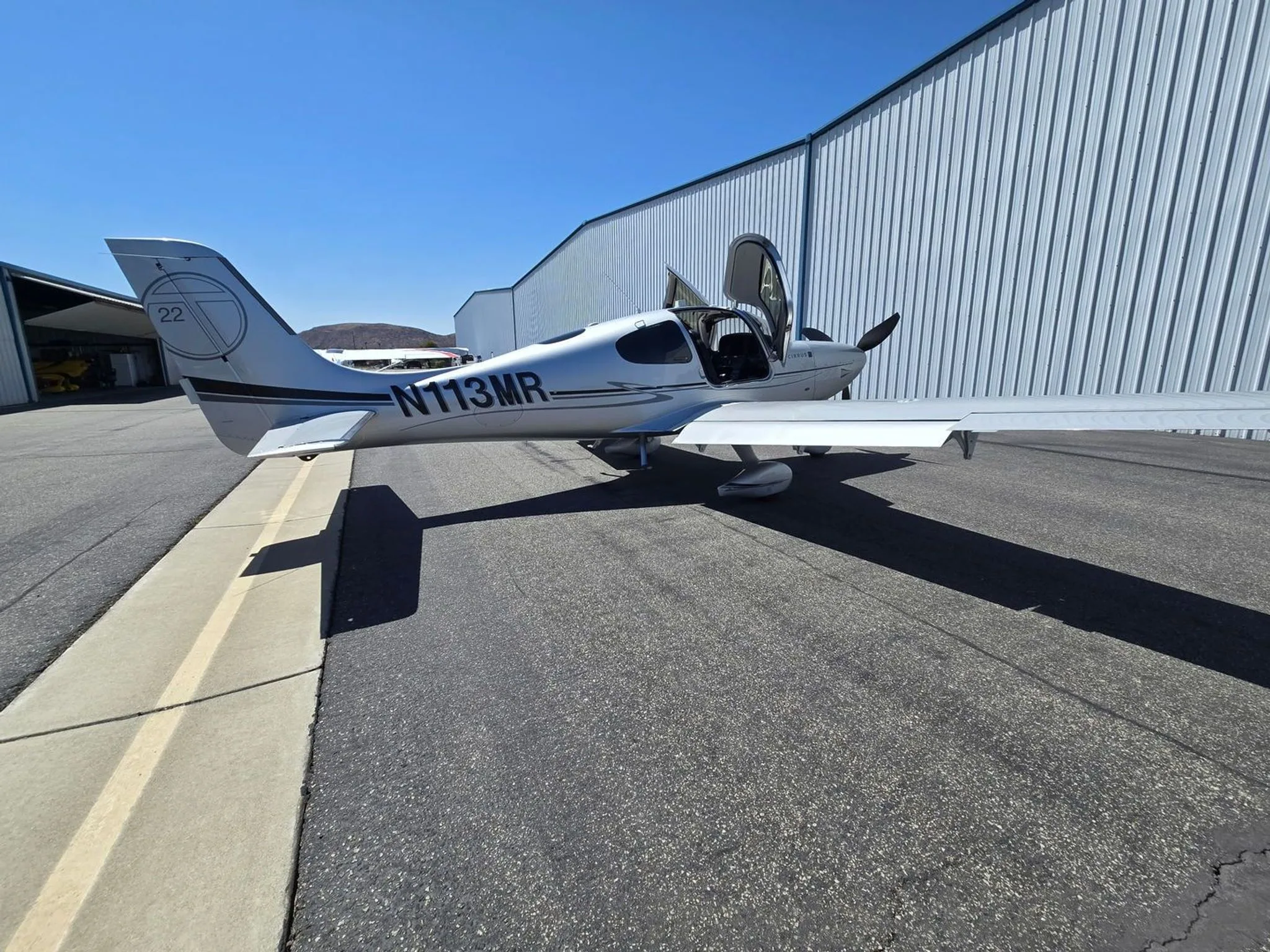


Free — save the SR22T to your watchlist and track it in one place.
More Cirrus SR22Tmanuals & documents
See all 21 →- Vantage 12 Pilot’s GuideV Speeds Reference
- Airworthiness Concern SheetAirworthiness Directives
- SERVICE BULLETIN HC-SB-30-390 Propeller - Spinner/Anti-ice Travel Tube InterferenceService Bulletins
- INSTRUCTIONS FOR INSTALLATION OF HARTZELL 4C1-F650A1/76C04(B)-0.6 PROPELLER ON CIRRUS SR22 AIRCRAFTMaintenance Manual
- INSTRUCTIONS FOR CONTINUED AIRWORTHINESS FOR HARTZELL 4C1-F650A1/76C04(B)-0.6 PROPELLER ON CIRRUS SR22T AIRCRAFTMaintenance Manual
- Supplemental Type Certificate SA03962ATSupplemental Type Certificate
- PILOT’S OPERATING HANDBOOK AND FAA APPROVED AIRPLANE FLIGHT MANUAL for the CIRRUS SR22Performance Data
- PILOT’S CHECKLIST SR22 G1 OR G2Checklist
- Continued Airworthiness Manual For Cirrus Design SR22 Series AirplanesMaintenance Manual
- Service Bulletin TAT SB10-01Service Bulletins
- Hartzell Engine Technologies Service Bulletin 033Service Bulletins
- SCHEDULE OF AIRWORTHINESS DIRECTIVESAirworthiness Directives
If you fly the Cirrus SR22T, you may also be researching these.



In this document
Engine Specifications
The SR22T is equipped with a TSIO-550-K engine, which is a TCM type certified engine rated at 315 horsepower at 2500 RPM and 36.5 inches of manifold pressure (MAP). The engine features a compression ratio of 7.5:1, which enhances detonation protection.
Normal Operating Procedures
Normal procedures include full throttle and mixture settings for takeoff, with a focus on monitoring manifold pressure to avoid overboost conditions. During climbs, pilots should maintain a climb speed of 120-130 KIAS and monitor cylinder head temperatures (CHT) to stay below 420°F.
Climb Techniques
The manual outlines two climbing techniques: Rich of Peak (ROP) and Lean of Peak (LOP). For ROP climbs, the power lever should be full forward, and the mixture should maintain fuel flow within the green arc. For LOP climbs, the power lever should be set to 30.5 inches MAP, and the mixture adjusted to a cyan target or less.
Fuel Management
Proper fuel management is crucial, with specific guidelines for leaning during taxi and cruise. The mixture should be adjusted to maintain optimal fuel flow and CHT, with recommendations for rich mixtures during takeoff and lean mixtures during cruise.
Emergency Procedures
The document includes emergency procedures for unexpected loss of manifold pressure, detailing steps for power adjustment, mixture management, and descent to a safe altitude.
Safety notes
- Monitor manifold pressure to avoid exceeding 37.0 inches during takeoff.
- Maintain CHT below 420°F to prevent engine roughness or damage.
Full document text
SR22T Engine Operations Agenda • How does it work? – SR22T Engine • Normal Operating Procedures • Data Review • Operations Discussion SR22T: TSIO-550-K ENGINE • TCM TYPE CERTIFIED ENGINE • 315 RATED HP @ 2500 RPM / 36.5” MAP – ADDITIONAL TAKEOFF HP RESULTS IN NOMINAL IMPROVEMENT IN TAKEOFF AND CLIMB PERFORMANCE • ENGINE COMPRESSION RATIO: 7.5:1 – PROVIDES HIGHER DETONATION PROTECTION SR22T: TSIO-550-K ENGINE • SINGLE WASTEGATE – SMALL WEIGHT REDUCTION – RELIABILITY AND MAINTENANCE BENEFITS • CONSISTENT 2500 RPM FIXED GOVERNOR – QUIET CABIN AND FLYOVER TAKEOFF AND CLIMB NOISE – VERY LOW TAKEOFF AND CLIMB VIBRATION LEVELS – SIMPLE SYSTEM RE: MAINTENANCE, RIGGING, SETUP – WEIGHT SAVINGS: PROP CONTROL CABLE AND APPARATUS ~1.5 LBS – PROP BRAKING: AT HIGH SPEED, LOW POWER BETTER DECELERATION Principles of Internal Combustion Engines 1. Induction: In this stroke the intake valve must be in the open position while the piston pulls an air-fuel mixture into the cylinder by producing vacuum pressure into the cylinder through its downward motion. 2. Compression: In this stroke the piston compresses the air-fuel mixture in preparation for ignition during the power stroke (below). Both the intake and exhaust valves are closed during this stage. 3. Power: While the piston is at T.D.C. (the end of the compression stroke) the compressed air-fuel mixture is ignited by a spark plug. This stroke produces mechanical work from the engine to turn the crankshaft. 4. Exhaust: During the exhaust stroke, the piston once again returns to T.D.C from B.D.C while the exhaust valve is open. This action expels the spent air-fuel mixture through the exhaust valve. Principles of Internal Combustion Engines • Air + Fuel + Spark = Combustion • What we Control – Air • Throttle – Manifold Pressure – RPM – Spark • Magnetos – L,R, Both – Fuel • Mixture – Cooling • Airspeed Power Lever/Throttle HOW WE CONTROL AIR Air Intakes • 2 combustion air intakes – 1 on each side connected to NACA vent • Fresh combustion air feeds directly into compressor-side of turbo Air Intakes / Alternate Air • Flexible tube connects intakes • Automatic alternate air door in center – Held shut by spring/magnet – Will open automatically when normal air sources become clogged – Will close automatically when resistance is cleared – CAS message will appear to alert pilot Intercooler (Aftercooler) • As the air is compressed in the turbo, it also warms up (up to 5 times as hot) • Intercooler is installed in the induction air path between the compressor and the throttle plate • The function is to cool down the compressed air, which improves the performance of the engine Throttle Controls Airflow To Throttle Control Power Lever Throttle Position • Manifold Pressure increases as the throttle opens • Airflow into the engine increases as the throttle opens • Engine behaves like an air pump Throttle Body Fuel Metering Cam • Increases fuel flow as throttle plate opens – Fuel flow increases at wide open throttle to help with engine cooling during climbs HOW WE CONTROL SPARK / IGNITION Magnetos Magnetos • Dual Magneto System • Gear driven from the accessory drive • Provides power to the spark plugs • Magnetos are pressurized by air from the upper deck • Prevents electric arcing within Mag Spark Plugs • Create spark/ignition for combustion event • 2 spark plugs/cylinder • Spark occurs 24° before piston reaches Top Dead Center (TDC) Magneto Timing • Advanced Timing Characteristics (Early) – High than normal CHTs – Lower than normal EGTs &TITs • Retarded Timing Characteristics (Late) – Low than normal CHTs – High than normal EGTs & TITs HOW WE CONTROL FUEL Mixture Lever Fuel System Electric Fuel Pump provides 4 to 6 PSI for vapor suppression Gascolator filters fuel before entering the engine driven fuel pump Mixture Lever Controls Fuel/Air Ratio Fuel Injectors • Pressurized by upper deck air – Prevents fuel backflow • Tuned – Specific to each cylinder Stoichiometric Ratio • If exactly enough air is provided to completely burn all of the fuel, the ratio is known as the stoichiometric mixture • Fuel to Air Ratio – 14.7 lbs Air : 1 lb Fuel • Too Rich or Too lean can lead to engine roughness or possible combustion failure Peak EGTLean Rich Mixture Influence • Peak EGT – “Stochiometric mixture” – All fuel and oxygen consumed – Air:Fuel ratio of 14.7 • Rich of Peak – Power limited by oxygen quantity – Excess fuel flow (fuel not consumed) provides cooling – Rich mixtures will have slight degrade on power – Excessively rich will flood engine (large power degrade, roughness or flameout) • Lean of Peak – Power limited by fuel quantity – Excess airflow (oxygen not completely consumed) provides cooling – Excessively lean lean misfire Rich of Peak (excess fuel flow) Lean of Peak (excess airflow) Engine Roughness at Lean of Peak • Caused by unbalanced fuel/air ratios • More apparent during lean of peak operations • Why? – Remember the HP curve in relation the fuel/air ratios 40 HP 50 HP 60 HP 65 HP 50 HP 45 HP 310 HP total output Unbalanced Injectors Unbalanced Fuel/Air Ratios • Some cylinders receive more fuel than others – ROP, Same HP / Smooth – LOP, Varying HP / Rough 40 HP 50 HP 60 HP 65 HP 50 HP 45 HP 310 HP Total Output Unbalanced Injectors LOP 52 HP 53 HP 51 HP 51 HP 52 HP 51 HP 310 HP Total Output Unbalanced Injectors ROP •Same HP •Smooth Engine Operation •Varying HP •Rough Engine Operation Unbalanced Fuel/Air Ratios Balanced Fuel/Air Ratios Balanced Fuel/Air Ratios 52 HP 53 HP 51 HP 51 HP 52 HP 51 HP 310 HP Total Output Balanced Injectors LOP & ROP • Each cylinder receiving same amount of fuel and air • All cylinders developing equal HP even on steep LOP curve SR22T TURBO SYSTEM COMPONENTS Turbocharger • A centrifugal compressor which boosts the intake pressure of an internal combustion engine driven by an exhaust gas turbine fitted to the engine's exhaust manifold. OVER-BOOST VALVE OPENING VALVE SPRING AND BELLOWS INDUCTION MANIFOLD
Show full textShow less
AIR CAN ESCAPE OPENING VALVE SPRING AND BELLOWS INDUCTION MANIFOLD AIR CAN ESCAPE • An overboost pressure relief valve is incorporated on turbocharged engine models to prevent over pressurization of the induction system • The overboost pressure relieve valve is set to open at roughly 2 to 4 inches of mercury above the rated maximum manifold pressure of the engine • This acts as a “fail safe” device to prevent the engine from reaching an overboost situation Turbo-Supercharger • Turbo uses accelerated exhaust gases to spin a compressor which increases the pressure in the upper deck • Capable of +100,000 RPM • Maximum Normal Turbo Inlet Temperature (TIT) is 1750°F, seen on MFD • Turbo is lubricated via the engine oil system Exhaust Combustion Air Wastegate • The waste-gate is a hydraulically controlled device using engine oil pressure, to close a butterfly valve that will direct exhaust gasses to the turbocharger ENGINE OIL PRESSURE “IN” OIL “OUT” TO SLOPED CONTROLLER Wastegate • The wastegate controls the amount exhaust that is allowed to flow through the turbo • Air will take the path of least resistance • A closed wastegate sends more exhaust through the turbo • An opened wastegate allows Exhaust to bypass the turbo and be dumped overboard • A spring holds the wastegate in the open position. Oil pressure closes the wastegate • There is only 1 wastegate that controls both turbos via a crossover tube Turbo Operation Crossover Tube • The left and right exhaust manifolds are connected via a crossover tube • This architecture equalizes exhaust pressure in the exhaust manifolds and both turbines are driven equally SLOPE CONTROLLER • Moves the wastegate to manage the pressure created by the turbo • Maintains a pressure differential across the throttle valve of about 4“ Hg at partial power settings and limits maximum MAP to 36.5” at full power SLOPE CONTROLLER SLOPE CONTROLLER • On takeoff at full power, slope controller limits MAP to 36.5” • As the aircraft climbs at full power and the ambient pressure decreases, the controller commands the wastegate to close to maintain 36.5” MAP • As power is reduced, the controller commands the wastegate to open to maintain the 4” differential across the throttle plate ADJUSTMENT SCREW OIL INLET PORT DECK PRESSURE SENSING PORT MANIFOLD PRESSURE SENSING PORT ANEROID BELLOWS ASSEMBLY DIAPHRAGM POPPET POPPET SEAT OIL DRAIN PORT ADJUSTMENT SCREW OIL INLET PORT DECK PRESSURE SENSING PORT MANIFOLD PRESSURE SENSING PORT ANEROID BELLOWS ASSEMBLY DIAPHRAGM POPPET POPPET SEAT OIL DRAIN PORT SR22T Power Lever • No connection or linkage to prop governor • Throttle cable “slowed” in cruise power range – Small changes in throttle position result in large changes to manifold pressure due to the slope controller MODIFIED ECS CONTROLLER • SR22T – LARGER HEAT EXCHANGER ON CROSSOVER TUBE, 50°F HIGHER HEAT RISE – USES ELECTRONIC CONTROL TO ACTIVELY MONITOR AND BIAS VALVES IF HOT AIR TEMP EXCEEDS LIMITS – BENEFITS ARE PLENTY OF HEAT ON THE GROUND, AND AT LOW AND HIGH ALTITUDES – PRESSURIZED PREVENTS CO The SR22T incorporates a cable-less Hartzel propeller governor. The governor operates on the same principle as other propeller governors; sensing engine speed, the governor regulates pressurized engine oil in the propeller piston assembly, which controls propeller blade angle. Begins controlling blade angle and engine speed at approximately 1400 RPMs. The engine reaches its maximum speed of 2500 RPMs at power settings as low as 55%. As the power lever is advanced, engine speed will remain at 2500 RPMs, but MAP and Fuel flow will increase as will % Power. With the high speed stop set at 2500 RPMs, additional power input causes the governor to increase propeller blade angle, thus increasing thrust. Prop Governor PUTTING IT TOGETHER So how does this all work? Take-Off • Turbos boost Manifold pressure to ~36.5” • Upper deck pressure regulated to ~36.5” by the slope controller Climb • Outside air pressure will begin to decrease • Manifold pressure would normally start to decrease as well, resulting in a loss of engine power Climb • Slope Controller – The aneroid in the slope controller contracts with loss of manifold pressure Climb • Slope Controller – The poppet closes restricting oil flow, building pressure in engine oil line to the wastegate Climb • The increased pressure in the oil line pushes against the waste gate spring closing the wastegate as needed Climb • As the wastegates close less exhaust air is allowed past the waste gates and more air directed through the turbos • This increase in airflow through the turbos increase the turbo’s RPM Climb • When the turbo’s RPMs increase the compressor will also start to spin faster • An increase in compressor RPMs will result in an increase in the Upper Deck manifold pressure • The upper deck manifold pressure will be regulated to maintain 36.5” up to about 18,000ft (critical altitude) Cruise • Manifold Pressure set to 30.5 or less (power lever) • The Slope Controller maintains upper deck pressure 4” higher (~34.5”) than the intake manifold – Allows for immediate power response • No need to wait for turbos to spool up if additional power is needed Climb to 25,000ft • Wastegates will be fully closed above 19,000ft (Critical Altitude) • All possible exhaust gas is directed through the turbos • As you climb above the critical altitude intake manifold pressure will begin to decrease • Engine should still be able to maintain 31” MAP and 85% power at 25,000 ft Cold Weather Takeoff • Pressure in the oil line to the wastegates may increase more than normal if the engine oil is not properly warmed before takeoff • The wastegate may close prematurely causing higher upperdeck pressures than desired • The pilot should reduce the power lever until MAP is below 37” • The pilot should increase throttle as the oil warms during the climb Cold Weather Departure • If the upperdeck pressure is allowed to reach too high of a level (2” to 4” above max rated) the over-boost valve will open reducing the pressure in the upperdeck LIMITATIONS SR22T Airspeed Limitations Speed KIAS Remarks Vne up to 17,500 MSL 200 (205 G5) Never Exceed Vne at 25,000 MSL 170 (175 G5) Vne is reduced linearly from 17,500 to 25,000 Vno up to 17,500 MSL 177 (176 G5) Maximum Structural Cruising Speed Vno at 25,000 MSL 151 (150 G5) Vno is reduced linearly from 17,500 to 25,000 Note: Vno and Vne can be interpolated for altitudes between 17,500 and 25,000. The PFD airspeed tape will change with altitude to reflect the difference in Vne / Vno System Limitations • Altitude Limits – Maximum Takeoff Altitude…...………………..10,000 MSL – Maximum Operating Altitude...........................25,000 MSL • Flap Limitation – Do not use flaps above………………..............17,500 MSL • Environmental Conditions – Do not operate the aircraft below an outside air temperature of - 40°C • Do not reduce manifold pressure below 15” when above 18,000 ft MSL Critical Altitude • Critical altitude is defined as the altitude at which the wastegate is completely closed and as the aircraft continues to climb, MAP will begin to decrease • Critical altitude ~19,000 ft • Aircraft will still be able to maintain 31” MAP and 85% power at 25,000 ft SR22T NORMAL OPERATIONS Continental Engine Certification • The engine is certified to 14 CFR 33 (Code of Federal Regulations) – Extensive requirements for Detonation – Every approved power setting has a minimum 12% detonation margin • What has CMI proven via testing – Cylinders can survive continuous operation at hot and high power settings – Engine parts remain “within service limits” – The FAA will approve 4X the test period as TBO – It is tested in very abusive conditions 103°F inlet air/240°F oil temp/460°F CHT – High power LOP may not have adequate (12%) Detonation Margin Normal Combustion Detonation • Detonation - Occurs when combustion of the air/fuel mixture in the cylinder does not start off correctly in response to ignition by the spark plug, but one or more pockets of air/fuel mixture explode outside the envelope of the normal combustion front • If allowed to persist engine damage is likely Detonation • During engine certification, with CHT at 460°F and manifold Air temp > 120°F (obstructions on intercoolers) detonation was observed at 31.5” Manifold Pressure Detonation SR22T Leaning Limitations • Leaning Prohibited if MAP > 30.5” – Detonation Margin • Indicate by Green Arc – Reduced if MAP > 30.7” – Wide if MAP ≤ 30.7” 30.7” Preflight • O2 preflight – O2 quantity, requirements and duration tables – Verify O2 flow to each mask/cannula that will be used • Pulse Oximeter – Check saturation levels on the ground and monitor during flight. – Adjust O2 flow to maintain saturation levels above 90% • Cannulas can not be used above FL180 as per FAR part 23. Masks must be worn above FL180. Plan accordingly. Oxygen Considerations • Do not use cannulas above FL180 • Passengers should be thoroughly briefed on the use of O2 including: – Proper use of masks/cannulas and flow regulators – Recognition and response to hypoxia – Recognition and response to pilot incapacitation • If saturation levels decrease below 90% – Increase to flow of O2 – Increase mask seal around face – Descend to a lower altitude if saturation level can not be maintained above 90% Normal Start (Cold) • Used for first start of the day or when engine (oil temps or CHTs) have cooled to ambient air temperatures Hot Weather Tips • Point the aircraft into the wind to increase airflow / cooling • Open the oil door to allow hot air to escape – Be sure to verify secure/closed before engine start Hot Start SR22T • Used when engine temperature is above ambient air temperature • No priming required for hot starts • Limit starter engagement to 10 seconds – Let cool for 20 seconds Hot Start • Liquid fuel may begin to expand and vaporize in hot weather conditions • Clearing the fuel lines of this vapor will be necessary prior to starting Flooded Start • Used if engine is expected to be flooded or if normal (hot) start was unsuccessful • Weak intermittent firing followed by puffs of black smoke from the exhaust stack indicates over- priming or flooding. Taxi • Leaning during Taxi will help to reduce the likelihood of sparkplug fouling • Lean to the “X” in Mixture or until Maximum RPM rise is achieved Run-Up • Part of the Before Takeoff Checklist – Perform as a flow use checklist to verify • Magneto Check – Max Drop 150 RPMs – Max Differential 75 RPMs • Check Engine Parameters – Verify normal indications Takeoff • Full throttle • Full mixture (for every altitude) • Boost pump on • Monitor MP for overboost – If the MP exceeds 37.0 inches reduce the throttle below 37.0 inches of MP – Due to cooler oil temperatures • Monitor Fuel Flow (Green Arc) – Will increase in proportion to manifold pressure Normal Procedures- Rich of Peak (ROP) Climb • Full Power Climb: Rich of Peak Technique – Power Lever – Full Forward – Mixture – Maintain Fuel Flow w/in Green Arc – CHT – Maintain below 420° F • Airspeed 120-130 Lean of Peak (LOP) Climb • Cruise Climb: Lean of Peak Technique – Power Lever – 30.5” MAP – Mixture – Cyan Target or less • FF Target will bias if CHT > 390 or Manifold air inlet temp increases above 85°F – CHT – Maintain below 420 ° F • Airspeed 120-130 • Lean as required to maintain <420 ° F – If unable use Full Power Climb Lean Misfire • Lean Misfire – Generally observed/characterized by sudden engine roughness • Typically occurs at air: fuel ratios > 18.5 (approximately corresponds to 120°F LOP) Full Power Climb vs. Lean of Peak Climbs Cruise Altitude (MSL) Fuel Savings LOP (Gallons) Range Increase LOP (NM) 2,000 .4 4 4,000 .7 8 6,000 1 13 8,000 1.4 17 10,000 1.8 23 12,000 2.1 27 14,000 2.5 33 16,000 2.9 38 18,000 3.3 44 20,000 3.6 52 22,000 4.2 59 24,000 4.7 67 25,000 5.1 71 Full Power Climb vs. Lean of Peak Climb Consider the following factors when deciding to climb LOP or ROP • Workload associated with LOP climbs – Closely monitor CHT’s – Adjusting mixture/airspeed for cooling • Decrease in climb performance • Significance of fuel savings • Significance of extra range Normal Procedures- Cruise • Cruise- Power settings will be lean of peak – Power Lever – 30.5” MAP or less – Fuel pump- As required • Low boost for at least 30 minutes – Mixture – Cyan target or less • 50 °-75°F lean of peak TIT – CHT’s – Maintain below 420 ° F • IF CHT’s are greater than 420 °F then lean .5 GPH – Should result in a 15 °F reduction in CHT temperature for every .5 GPH • 390° - 400°F CHT’S TYPICAL Boost Pump Operation • Pressure affects the temperature required to vaporize fuel – Lower pressure = lower vaporization temperature • Low boost provides extra pressure to keep fuel from vaporizing at high altitude • High boost may be necessary above FL180 with warm or hot fuel if vapor lock is present • Vapor lock can be recognized in flight by: – Fluctuations in normal fuel flow – Rising EGTs and TIT coupled with falling fuel flow – Rising CHTs Maneuvering • Boost Pump On for any maneuvering – Flight training maneuvers, chandelles, stalls, etc. • Mixture set as required – Normally full rich Descent • Power Lever – As Required • Mixture – Cyan Target or less • CHT – Maintain in green arc (above 240° F) • Avoid Prolonged idle settings • Rapid Descent – Power lever - Smoothly reduce MAP 18 to 20” Before Landing • Mixture (SR20) – Set Full Rich • Ensures for maximum power in case of a go around • Mixture (SR22) – Lean to a setting that will result in placarded fuel flows if throttle is advanced to wide open – Below 4,000ft PA Full Rich • Boost Pump ON Taxi • Leaning during Taxi will help to reduce the likelihood of sparkplug fouling • Lean to the “X” in Mixture or until Maximum RPM rise is achieved REVIEW SR22T Operations True or False? • Leaning the engine will cause the CHT’s to rise when operating lean of peak. Scenario During a lean of peak climb while climbing at 120 KIAS the CHT’s exceed 420° F – What is the appropriate response? – What if that does not work? – What if that does not work? Scenario After setting cruise power at 85% (2500RPM / 30.5” MP and 18.3 GPH) the CHT’s remain at 420° F. – What is the appropriate action? Emergency Procedures Specific to Turbo Operations Scenario • While cruising at 17,000ft you notice a sudden loss of manifold pressure. – What do you do now? Unexpected Loss of Manifold Pressure Four Most Probable Causes 1. Leak in the induction system • Behaves like a normally aspirated airplane 2. Leak in the exhaust system • Possible fire hazard 3. Loss of oil pressure to wastegate actuator • Due to general loss of engine oil 4. Failure of internal component in turbocharger • May be accompanied by loss of oil pressure Unexpected Loss of Manifold Pressure Emergency Procedure: 1. Power- Adjust to minimum required 2. Mixture-Adjust for EGT’s between 1300 ° to 1400 °F 3. Descend to Minimum Safe Altitude from which a landing may be safely accomplished 4. Divert to nearest suitable airfield 5. Radio-121.5 advise ATC 6. Oil Pressure-Monitor 7. Land as soon as possible Questions? Data Review Starter engagement up to 30 seconds observed, Continental and POH limit is 10 seconds with 20 second “cool-down” between tries. Operation near peak EGT: 30.2”MP with 19.3 GPH FF, more normal FF would be around 18 GPH at this MP. This was seen on a couple flights. Excessive time used in transitioning from ROP to LOP, sometimes this exceeds 1 minute. This results in the engine running near peak EGT for longer than necessary. Using the LOP target and more quickly moving the mixture to the LOP target will result in less time at peak EGT. Climbing LOP in the pattern then immediately reducing power
What's in the Cirrus SR22T TCDS
A Type Certificate Data Sheet (TCDS) is the FAA's record of what an aircraft type was approved as. It is the source of truth for weights, seating, fuel and the rules the design was certified against. Expand any line to see what it means.
1,001 Cirrus SR22T parts for sale
See all →
Parts listed for sale by vetted eBay sellers — confirmed on eBay at checkout.