CIRRUS AIRFRAME PARACHUTE SYSTEM MAINTENANCE MANUAL with ILLUSTRATED PARTS LIST
Cirrus SR22T · Parts Catalog
Overview
This document is the Cirrus Airframe Parachute System (CAPS) Maintenance Manual, which includes an Illustrated Parts List. It is specifically designed for authorized technicians to maintain and service the CAPS installed in Cirrus SR20 and SR22 airplanes. The manual outlines procedures for the maintenance of the parachute system, including installation, removal, and servicing of various components. It emphasizes the importance of using trained personnel for maintenance tasks and provides detailed instructions for handling the system safely. The manual is structured to facilitate easy identification of parts and procedures, ensuring that technicians can restore the system to a functional condition effectively.
- CAPS must be serviced by trained technicians only.
- The parachute system is designed to deploy safely in emergencies, requiring two pilot actions.
- The rocket motor reaches full extension in 2.5 seconds after activation.
- Ground activation can cause extensive damage and injury; it should never be performed on the ground.
- The parachute canopy has a surface area of 2400 square feet.
Document
Source
Originally published by befa.org. Sprinkle hosts a reference copy with an added summary, specifications and searchable full text.
Document details
- Type
- Parts Catalog
- Year
- 2002
- Pages
- 48
- File size
- 2.3 MB
- Publisher
- befa.org
Common. One of the most common aircraft types we track.
Most owners only have the POH. Here's the essential set for the Cirrus SR22T.
- Pilot's Operating Handbook / AFM
- Checklist
- Maintenance Manual
- Parts Catalog (IPC)
- Systems & Wiring
- Service Bulletins
- Type Certificate (TCDS)
Cirrus SR22T for sale now
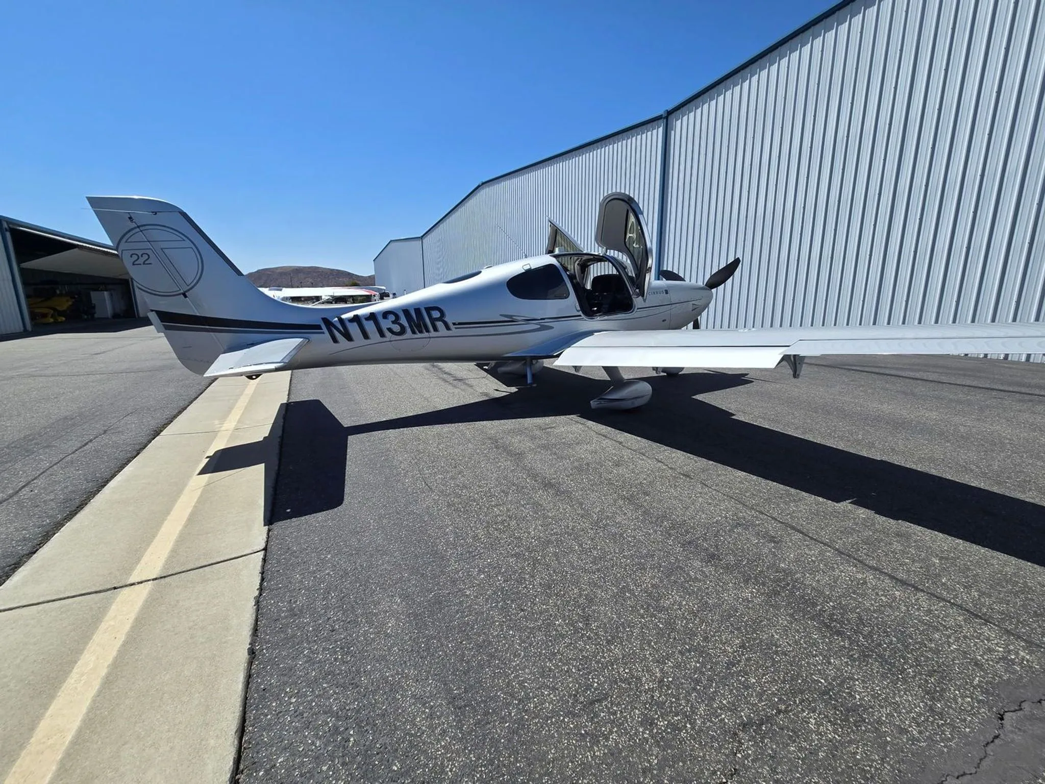


Free — save the SR22T to your watchlist and track it in one place.
More Cirrus SR22Tmanuals & documents
See all 21 →- Vantage 12 Pilot’s GuideV Speeds Reference
- Airworthiness Concern SheetAirworthiness Directives
- SERVICE BULLETIN HC-SB-30-390 Propeller - Spinner/Anti-ice Travel Tube InterferenceService Bulletins
- INSTRUCTIONS FOR INSTALLATION OF HARTZELL 4C1-F650A1/76C04(B)-0.6 PROPELLER ON CIRRUS SR22 AIRCRAFTMaintenance Manual
- INSTRUCTIONS FOR CONTINUED AIRWORTHINESS FOR HARTZELL 4C1-F650A1/76C04(B)-0.6 PROPELLER ON CIRRUS SR22T AIRCRAFTMaintenance Manual
- Supplemental Type Certificate SA03962ATSupplemental Type Certificate
- PILOT’S OPERATING HANDBOOK AND FAA APPROVED AIRPLANE FLIGHT MANUAL for the CIRRUS SR22Performance Data
- PILOT’S CHECKLIST SR22 G1 OR G2Checklist
- Continued Airworthiness Manual For Cirrus Design SR22 Series AirplanesMaintenance Manual
- Service Bulletin TAT SB10-01Service Bulletins
- Hartzell Engine Technologies Service Bulletin 033Service Bulletins
- SCHEDULE OF AIRWORTHINESS DIRECTIVESAirworthiness Directives
If you fly the Cirrus SR22T, you may also be researching these.




In this document
Introduction
The introduction outlines the purpose of the CAPS Maintenance Guide, which is to provide procedures for authorized technicians to maintain the parachute system. It specifies that the manual is applicable to SR20 airplanes serial numbers 1195 and subsequent, and SR22 airplanes serial numbers 0210 and subsequent.
General Description
This section describes the CAPS, which includes a parachute, a solid-propellant rocket, and an activation system. It explains how the system is designed to safely bring the aircraft and its occupants to the ground in emergencies.
Activation System
The activation system requires two deliberate actions from the pilot to deploy the parachute. It details the components involved, including the activation handle and the rocket motor, and explains the sequence of events that occur upon activation.
Maintenance Guide
The maintenance guide section provides detailed procedures for servicing the CAPS, including the removal and installation of pyrotechnic line cutters and the CAPS cover. It emphasizes the need for trained technicians to perform these tasks.
Illustrated Parts List
This section includes a comprehensive list of parts associated with the CAPS, aiding technicians in identifying and procuring necessary components for maintenance.
Safety notes
- Never activate CAPS on the ground; it can cause injury and damage.
- Rocket ignition can occur at temperatures above 500°F (260°C).
- Ensure all maintenance is performed by authorized personnel to avoid system failure.
Full document text
CIRRUS AIRFRAME PARACHUTE SYSTEM MAINTENANCE MANUAL with ILLUSTRATED PARTS LIST For the CIRRUS DESIGN SR Series Airplane CIRRUS DESIGN INCORPORATED 4515 Taylor Circle Duluth, MN 55811 FAA APPROVAL HAS BEEN OBTAINED ON THE TECHNICAL DATA IN THIS PUBLICATION THAT AFFECTS AIRPLANE TYPE DESIGN. COPYRIGHT 2002 CIRRUS DESIGN CORPORATION DULUTH, MINNESOTA, USA P/N 12128-001 ISSUED SEPT, 2002 Procedures and parts listed in this manual are reflective of Cirrus Design SR20 airplanes serial numbers 1195 and subsequent, SR22 airplanes serial numbers 0210 and subsequent, and all prior airplanes incorporating Service Bulletin SB 20-95-05 or SB 22-95-05 respectively. 12128-001 95-RevLog Page 1 Log of Revisions Revision Number Issue Date Date Inserted Inserted By Revision Number Issue Date Date Inserted Inserted By 15 Sept 2002 12128-001 95-LOEP Page 1 CHAPTER 95 - CIRRUS AIRFRAME PARACHUTE SYSTEM LIST OF EFFECTIVE PAGES Chapter/Section Page Date 95-REVLOG 1 15 SEPT 2002 95-LOEP 1 15 SEPT 2002 95-LOEP 2 15 SEPT 2002 95-TOC 1 15 SEPT 2002 95-TOC 2 15 SEPT 2002 95-01 1 15 SEPT 2002 95-01 2 15 SEPT 2002 95-01 3 15 SEPT 2002 95-01 4 15 SEPT 2002 95-01 5 15 SEPT 2002 95-01 6 15 SEPT 2002 95-01 7 15 SEPT 2002 95-01 8 15 SEPT 2002 95-01 9 15 SEPT 2002 95-01 11 15 SEPT 2002 95-01 12 15 SEPT 2002 95-01 13 15 SEPT 2002 95-01 14 15 SEPT 2002 95-01 15 15 SEPT 2002 95-01 16 15 SEPT 2002 95-01 17 15 SEPT 2002 95-01 18 15 SEPT 2002 95-01 19 15 SEPT 2002 95-01 20 15 SEPT 2002 95-01 21 15 SEPT 2002 95-01 22 15 SEPT 2002 95-01 23 15 SEPT 2002 95-01 24 15 SEPT 2002 95-01 25 15 SEPT 2002 95-01 26 15 SEPT 2002 95-01 27 15 SEPT 2002 95-01 28 15 SEPT 2002 95-01 29 15 SEPT 2002 95-01 30 15 SEPT 2002 95-01 31 15 SEPT 2002 95-01 33 15 SEPT 2002 95-01 34 15 SEPT 2002 95-01 35 15 SEPT 2002 15 Sept 2002 12128-001 95-LOEP Page 2 CHAPTER 95 - CIRRUS AIRFRAME PARACHUTE SYSTEM LIST OF EFFECTIVE PAGES Chapter/Section Page Date 95-01 36 15 SEPT 2002 95-01 37 15 SEPT 2002 95-01 38 15 SEPT 2002 95-01 39 15 SEPT 2002 95-01 40 15 SEPT 2002 15 Sept 2002 12128-001 95-TOC Page 1 CHAPTER 95 - CIRRUS AIRFRAME PARACHUTE SYSTEM TABLE OF CONTENTS Subject Chapter/Section Page INTRODUCTION 95-01 1 Purpose 1 Using the CAPS Component Manual 1 Page Numbering System 1 Warnings, Cautions, and Notes 1 General 2 Description and operation 2 Activation System 4 Solid Propellant Rocket Motor Assembly 4 Rocket Igniter 4 Rocket Motor 4 Incremental Bridle and Deployment Bag 6 Parachute Assembly 6 Canopy and Suspension Lines 6 Slider 8 Airplane Attachment Harness 8 MAINTENANCE GUIDE 95-01 11 General 11 Servicing - Cirrus Airframe Parachute System 11 Removal - Pyrotechnic Line Cutters Replacement 11 Installation - Pyrotechnic Line Cutters Replacement 12 CAPS Cover 15 Removal - CAPS Cover 15 Installation - CAPS Cover 15 CAPS Rocket Assembly 20 Removal - CAPS Rocket Assembly 20 Disassembly - CAPS Rocket Assembly 20 Reassembly - CAPS Rocket Assembly 20 Installation - CAPS Rocket Assembly 21 CAPS Parachute Assembly 24 Removal - CAPS Parachute Assembly 24 Installation - Caps Parachute Assembly 24 Caps Activation Handle and Cable Assembly 25 Removal - Caps Activation Handle and Cable Assembly 25 Installation - Caps Activation Handle and Cable Assembly 26 Operational Check - Caps Activation Handle and Cable Assembly 27 15 Sept 2002 12128-001 95-TOC Page 2 CHAPTER 95 - CIRRUS AIRFRAME PARACHUTE SYSTEM TABLE OF CONTENTS Subject Chapter/Section Page ILLUSTRATED PARTS LIST 95-01 33 General 33 SR2X CAPS Installation (Sheet 1 of 3) 34 SR2X CAPS Installation (Sheet 2 of 3) 35 SR2X CAPS Installation (Sheet 3 of 3) 36 15 Sept 2002 12128-001 95-01 Page 1 15 Sept 2002 INTRODUCTION 1. PURPOSE The purpose of the Cirrus Design CAPS Maintenance Guide with Illustrated Parts List (CAPS Component Manual) is to provide shop verified procedures that will enable an authorized CAPS technician to restore the system to a functional condition. Procedures and parts listed in this manual are reflective of Cirrus Design SR20 airplanes serial numbers 1195 and subsequent, SR22 airplanes serial numbers 0210 and subsequent, and all prior airplanes incorporating Service Bulletin SB 20-95-05 or SB 22-95-05 respec- tively. These procedures are prepared for authorized Cirrus Design CAPS technicians only. Note: CAPS must be serviced and maintained by Cirrus Design trained and authorized parachute system technicians only. Airframe and Powerplant license is not sufficient credentials for per- forming maintenance on CAPS. This manual was prepared using GAMA Specification #2 (Specification for Manufacturers Maintenance data), Revised September 1982 as a content model and format guide. However, as the specification is writ- ten to cover a whole class of aircraft rather than a particular model, some deviations from the specification were made for clarity. 2. USING THE CAPS COMPONENT MANUAL This CAPS Component Manual is divided into two major sections; the CAPS Maintenance Guide which outlines approved maintenance practices, and the CAPS Illustrated Parts List, prepared to aid technicians in identifying and procuring replacement parts. A. Page Numbering System Page numbers used in this manual consist of two-element numbers separated by dashes, under which the page number and date are printed. The chapter/system number corresponds to the GAMA Specification #2 system title. The second two- element number is assigned by Cirrus Design and denotes the issue number of the respective chapter title. First Element Second Element Chapter Issue XX - XX B. Warnings, Cautions, and Notes Warnings, Cautions, and Notes are used to highlight or emphasize important points. WARNING: Warnings call attention to use of materials, processes, methods, procedures, or limits which must be followed precisely to avoid bodily injury.
Show full textShow less
CAUTION: Cautions call attention to methods and procedures which must be followed to avoid damage to equipment. Note: Notes call attention to methods which make the procedure easier. 12128-001 95-01 Page 2 15 Sept 2002 3. GENERAL The airplane is equipped with a Cirrus Airplane Parachute System (CAPS) designed to bring the aircraft and its occupants to the ground in the event of a life-threatening emergency. CAPS consists of a parachute, a solid-propellant rocket to deploy the parachute, a rocket activation sys- tem, and a harness imbedded within the fuselage structure. A composite enclosure containing the parachute and solid-propellant rocket is mounted to the airplane structure immediately aft of the baggage compartment bulkhead. The enclosure is covered and protected from the elements by a thin composite cover. The parachute is enclosed within a deployment bag that stages the deployment and inflation sequence. The deployment bag creates an orderly deployment process by allowing the canopy to inflate only after the rocket motor has pulled the parachute lines taut. The parachute itself is a 2400-square-foot round canopy equipped with a slider, an annular-shaped fabric panel with a diameter significantly less than the open diameter of the canopy. The canopy suspension lines are routed through grommets so that the slider is free to move along the suspension lines. Since the slider is positioned at the top of the suspension lines near the canopy, at the beginning of the deployment sequence, the slider limits the initial diameter of the parachute and the rate at which the parachute inflates. The canopy inflates as the slider moves down the suspension lines. A three-point attachment harness connects the airplane to the parachute. The harness consists of two for- ward straps faired into the fuselage skin and attached to the firewall, and one rear strap attached to FS 222 bulkhead located directly forward of the CAPS enclosure. The harness system is designed to control the pitch dynamics of the airplane during the deployment cycle by limiting the aft attachment strap’s length until the cycle is complete. This is accomplished by utilizing a variable length strap section. The shorter section, which initially supports the load, employes a mechanical release that is activated by two pyrotechnic cut- ters which fire when the short section is pulled taut during extraction. The harness strap then lengthens and load is transferred to the longer section. 4. DESCRIPTION AND OPERATION (SEE FIGURE 95-011) Two separate and deliberate pilot actions are required to deploy the CAPS parachute. The first action requires the pilot to remove the access cover from the activation handle enclosure. The second action requires the pilot to pull the activation handle out, and down several inches. Upon pulling the activation handle, the activation cable compresses the igniter’s steel spring, cocks the plunger and the following sequence is initiated: When one half-inch of plunger travel is reached, captured ball-bearings are released allowing the plunger to strike the firing pins. The firing pins strike two primers which ignite the primary booster. The primary booster ignites a secondary booster ensuring ignition of the larger rocket motor. Once ignited, the rocket propellant’s hot gases are exhausted through the nozzle and the rocket bursts through the CAPS enclosure cover pulling the deployment bag from the enclosure. The deployment bag then stages the suspension line deployment and inflation of the parachute. As the para- chute inflates, the forward harness assembly grows taut, pulls free of the fuselage skin, and stops at the firewall compression tube which supports the forward portion of the airplane. The rear harness’ shorter section is pulled taut, initiates the pyrotechnic line cutters which sever the shorter lines, and allow the longer harness section to support the aft load. The airplane then assumes its touchdown attitude; approxi- mately ten degrees nose down, to optimize occupant protection. 12128-001 95-01 Page 3 Figure 95-011 CAPS System and Deployment 15 Sept 2002 12128-001 95-01 Page 4 15 Sept 2002 A. Activation System (See Figure 95-012) The rocket motor is activated by pulling an activation handle mounted in a recessed enclosure located in the headliner above the pilot/copilot. This handle is connected to the rocket motor igniter with a flex- ible, stainless steel aircraft grade cable routed through a cable housing above the cabin ceiling head- liner. A cover/placard is attached to the perimeter of the activation handle enclosure to prevent the handle from being pulled accidentally. The placard identifies the system, presents the actions required to deploy it, defines its operating envelope, provides appropriate warnings, and references the airplane Flight Manual. A maintenance safety pin is provided to ensure that the activation handle is not pulled during mainte- nance or other ground operation. The pin is inserted through the handle retainer and barrel locking the handle in the “safe” position. A “Remove Before Flight” streamer is attached to the pin. The handle is the only part of the system accessible to the pilot in flight. B. Solid Propellant Rocket Motor Assembly (See Figure 95-012) The CAPS rocker motor assembly consists of the igniter, rocket motor, and rocket motor base. The igniter consists of a steel spring, a plunger, two firing trains, and a firing pin actuator to which the acti- vation cable is attached. Each firing train consists of a firing pin and primer which ignites a booster. In its normal position the firing pin actuator and plunger are interlocked with two ball bearings held in place by the inner wall of the igniter body. (1) Rocket Igniter Pulling the activation cable compresses the rocket igniter spring and cocks the plunger. One half-inch of plunger travel is required to release the ball bearings and allow the plunger to strike the firing pins. The firing pins then strike the shotgun-type primers which ignite a black powder and magnesium primary booster in the end of the igniter. The igniter is unarmed in its normal configuration since the spring is un-compressed and the plunger is separated from the firing pins by a 0.060-inch gap. The igniter primary booster ignites a secondary black powder and magnesium booster contained in the rocket motor base. The extra booster material is used to ensure ignition of the larger rocket motor. The rocket motor base has a conical protrusion which sprays hot particles past the rocket nozzle and across the surface of the rocket motor's solid propellant. Once ignited, the grains will burn on all exposed surfaces to form hot gases which are exhausted through the nozzle provid- ing thrust. (2) Rocket Motor The CAPS rocket motor uses stored chemical energy in the form of a solid propellant to provide the thrust forces necessary to rapidly remove the enclosure cover and extract the parachute from its enclosure. The rocket motor components consist of the motor case, motor aft bulkhead, propellant, and nozzle. The motor case/aft bulkhead contains the propellant and serves as a pressure chamber when the propellant is burning. The rocket motor uses a composite propellant, consisting of a heterogeneous mixture of ammo- nium perchlorate (AP) and aluminum powder (Al), the oxidizer and fuel. These are the most commonly used types of these ingredients in modern solid propellants. The rocket motor nozzle provides for the expansion and supersonic acceleration of the hot gases. The rocket motor has been designed to specifically meet the extraction requirements of the CAPS parachute. 12128-001 95-01 Page 5 Figure 95-012 CAPS Handle and Ignition System 15 Sept 2002 12128-001 95-01 Page 6 15 Sept 2002 C. Incremental Bridle and Deployment Bag (See Figure 95-013) The rocket motor is attached to the deployment bag via a set of Teflon sheathed stainless steel cables, or rocket lanyards, and an incremental bridle. The incremental bridle consists a length of nylon web- bing that is folded in half and sewn with a series of bartack stitches. Upon activation these stitches are peeled away to provide proper rocket/bag dynamics by acting as a shock absorber. The incremental bridle, which is connected to the end of the rocket lanyards is protected from the rocket exhaust by a heavy kevlar sheath. A deployment bag is used to contain the packed parachute assembly within the fuselage enclosure and stage its deployment and inflation sequence. The parachute assembly is packed into two compart- ments within the deployment bag. The innermost compartment contains the canopy and is secured by an internal flap that is locked in place with a series of locking loops to ensure that the canopy cannot be extracted from its compartment until the suspension lines, stored in the outer compartment, are pulled taut, and the line stows are extracted from the locking loops that hold the flaps closed. The suspension lines are secured with a hook and loop closure. The four outer flaps are secured with five steel curved release pins attached to the riser. The pins are extracted when the riser is pulled taut during extraction. The deployment bag creates an orderly deployment process by allowing the canopy to inflate only after the rocket motor has pulled the aircraft attachment harness, riser and suspension lines taut and pulled the deployment bag off the canopy. This prevents any slack or uneven tension in the suspension lines during canopy inflation that could result in a malfunction. D. Parachute Assembly (See Figure 95-014) The parachute slows the airplane to a descent speed that is conducive to a safe touchdown. The basic structure of the parachute assembly consists of the canopy, suspension lines, and the slider; a compo- nent used to aerodynamically reef the parachute and limit inflation loads. (1) Canopy and Suspension Lines The 2400 sq ft round canopy, which creates the aerodynamic drag, is made up of a series of fab- ric panels sewn together to form its desired shape. The canopy has a vent at its center to allow some air to escape in a controlled manner and thus reduce oscillations and provide a stable descent. Vent lines are attached to the perimeter of the vent and routed symmetrically across its center to provide structural support and maintain its shape. The suspension lines are attached to the “skirt” of the canopy and converge to a riser or set of risers at the opposite end. The canopy structural integrity is enhanced by a “skeleton” of tapes and webbings sewn nearly perpendicular to each other to the top surface of the canopy fabric. Radial bands run from opposite suspension line attachment points, across the top of the canopy. The skirt band, vent band, and lateral bands run around the circumference of the canopy. The CAPS parachute is fabricated from woven textiles in the form of fabrics, tapes, webbing, and thread. All of the textile components in CAPS are fabricated from either Kevlar or Nylon and are woven to military specifications that define specific parameters such as yarn count, yarn twist, weave type, and finish. To insure good aging characteristics, the only exception to the use of Kevlar and Nylon is a Teflon cloth buffer on the risers at the suspension line attachment point. A typical deployment load profile begins with a snatch force which occurs when the parachute assembly is initially extracted from its container and pulled to full line stretch. When air begins to fill the canopy, inflation loads result. The parachute is designed to deploy without generating forces high enough to injure the airplane occupants. 12128-001 95-01 Page 7 Figure 95-013 Incremental Bridle and Deployment Bag 15 Sept 2002 12128-001 95-01 Page 8 15 Sept 2002 (2) Slider To limit inflation loads, CAPS uses a slider to aerodynamically reef the parachute. The slider is a flat annular shaped fabric panel with metal grommets attached to its perimeter. The parachute suspension lines are routed through the grommets so that the slider is free to move along the suspension lines. The slider, which has a significantly smaller diameter than the fully inflated parachute, is positioned at the top of the suspension lines, next to the canopy skirt, when the parachute is packed. It therefore limits the initial inflated diameter of the parachute and hence the inflation loads. During inflation, the slider remains next to the skirt for a period of time that is dependent on the dynamic pressure acting on the system. This allows the payload to decelerate to a speed at which the parachute can fully inflate without generating excessive loads. E. Airplane Attachment Harness (See Figure 95-014) An aircraft harness system connects the parachute risers to the airplane primary structure. The CAPS aircraft harness consists of two forward harness straps attached to the firewall and a rear harness attached to the FS 222 bulkhead located directly in front of the parachute enclosure. The CAPS har- ness system is designed to control the pitch dynamics of the airplane during the deployment cycle by limiting the aft aircraft attachment harness length until the deployment cycle is complete. The rear harness assembly has two sections of different length. The shorter section has a mechanical release mechanism that is activated by two pyrotechnic reefing line cutters. The fuses on these line cutters are initiated when the line cutter release pin is pulled when the harness is pulled taut during the extraction. After 8 seconds, the line cutters fire, the longer section of the rear harness takes over and the airplane assumes its touchdown attitude, approximately ten degrees nose down, to optimize occu- pant protection. The release mechanism design is based on a 3-ring release mechanism. This system uses a series of metal rings routed through each other in a manner that provides a significant mechanical advantage. For the mechanism to be released, each link must rotate through its adjacent ring or link. The force necessary to hold the small link in its stowed position is considerably smaller than the force that is being applied as a result of the overall load on the mechanism. On the CAPS system the last link is held in place by a short length of nylon cord which is severed by the pyrotechnic reefing line cutters. 12128-001 95-01 Page 9 Figure 95-014 Parachute Assembly and Line Cutters 15 Sept 2002 THIS PAGE INTENTIONALLY LEFT BLANK 12128-001 95-01 Page 11 15 Sept 2002 MAINTENANCE GUIDE 1. GENERAL Procedures and parts listed in this manual are reflective of Cirrus Design SR20 airplanes serial numbers 1195 and subsequent, SR22 airplanes serial numbers 0210 and subsequent, and all prior airplanes incor- porating Service Bulletin SB 20-95-05 or SB 22-95-05 respectively. WARNING: CAPS must be serviced and maintained by Cirrus Design trained and authorized para- chute system technicians only. Airframe and Powerplant license is not sufficient cre- dentials for performing maintenance on CAPS. Never activate CAPS on the ground. The rocket exits the fuselage with a velocity of 150 mph in the first tenth of a second and reaches full extension in 2.5 seconds. Peo- ple near the airplane may be injured and extensive damage to the airframe will occur. Ground activation will cause the airplane to be out of service until CAPS is replaced and the airframe repaired and inspected. Rocket ignition will occur at temperature above 500° F (260° C). In the event of ground fire, use necessary precautions to avoid CAPS deployment. FAA Type Certification for the airplane is contingent on a functional Cirrus Airframe Parachute System (CAPS). The airplane may not be flown when CAPS is rendered inoperative. Note: CAPS part identification and descriptions can be found in the Illustrated Parts List section of this manual. A. Servicing - Cirrus Airframe Parachute System (See Figure 95-015) (1) Removal - Pyrotechnic Line Cutters Replacement (a) Acquire necessary tools, equipment, and supplies. (b) Remove CAPS handle access cover and install CAPS handle safety pin (c) Remove bulkhead 222 (BH 222) trim panel and carpet. (d) Remove access panel CB7 from BH 222. (Refer to AMM 6-00) (e) To prevent debris and components from falling into bottom of empennage, place catch cloth below rocket and parachute assembly. (f) Pull open flaps secured with hook and loop to gain access to line cutters. (g) Remove line cutter lanyard from D-ring and un-thread lanyard routed through line cutter’s ignition loops. WARNING: When cutting nylon cord, ensure three-ring assembly stackup is not altered. (h) Cut and remove nylon cord securing line cutters to link assembly. (i) Remove line cutters from airplane and safely discard. Description P/N or Spec. Supplier Purpose Pyrotechnic Line Cutter Replacement Kit TBD Cirrus Design Replacment. 12128-001 95-01 Page 12 15 Sept 2002 (2) Installation - Pyrotechnic Line Cutters Replacement (a) Ensure CAPS handle safety pin is installed. (b) Verify three-ring release assembly is correct. (c) Thread new nylon cord through mini-ring and pull cord ends equal. (d) Thread nylon cord ends, through small link. (e) Thread one end of nylon cord through installation hole on first new line cutter. (f) Thread opposite end of nylon cord through installation hole on second new line cutter. Note: Use a short, thin piece of wire wrapped around the nylon cord ends to facili- tate routing the nylon cord through the rear harness sleeve. (g) Wrap wire around nylon cord ends, insert wire into sleeve, and route cord through rear harness sleeve. (h) Pull nylon cord completely through sleeve so mini-ring cinches up against top surface of small link. (i) Position line cutters inside securing flaps and route nylon cord up, between link cutters. (j) With one end of nylon cord make one complete loop around mini-ring. CAUTION: Ensure no slack exists in nylon cord between rear harness sleeve and mini- ring and line cutter installation holes and small link. (k) Cinch nylon cord tight. (l) Tie CAPS knot: 1 Cross upper cord end (end looped around mini-ring) over lower cord end twice. i.e. right over left, right over left. 2 Cinch nylon cord tight. 3 Tie standard Square Knot and cinch tight. (m) Sew nylon cord ends together just below CAPS knot, tie off with CAPS knot. CAUTION: Ensure trimmed ends of nylon cord do not interfere with line cutter’s ignition loops. (n) Trim nylon cord to one inch (2.5 cm). (o) Route line cutter lanyard through line cutter’s ignition loops and secure lanyard to D-ring. (p) Close hook and loop securing flaps. (q) Remove catch cloth from below rocket and parachute assembly. (r) Install access panel CB7 to BH 222. (s) Install BH 222 trim panel and carpet. 12128-001 95-01 Page 13 Figure 95-015 Pyrotechnic Line Cutters Replacement (Sheet 1 of 2) 15 Sept 2002 12128-001 95-01 Page 14 Figure 95-015 Pyrotechnic Line Cutters Replacement (Sheet 2 of 2) 15 Sept 2002 12128-001 95-01 Page 15 15 Sept 2002 B. CAPS Cover (See Figure 95-016) (1) Removal - CAPS Cover (a) Acquire necessary tools, equipment, and supplies. (b) Remove CAPS handle access cover and install CAPS handle safety pin. (c) From aft edge of rear window and along airplane center line, measure 6.0 inches (15.2 cm) aft and mark the CAPS cover edge-seam location. CAUTION: Exercise caution when sanding composite surface to prevent sanding into laminate. Control dust migration. (d) Using die grinder and disc, at CAPS cover edge-seam reference mark, sand in a 0.5 inch (1.3 cm) area, and locate CAPS cover seam line. Sand around cover circumference follow- ing seam line to reveal entire perimeter of cover. WARNING: Use utmost care when working around embedded forward harness straps and lightening protection mesh with sharp tools. Failure to fol- low this WARNING could result in damage to CAPS system and failure upon deployment. Note: CAPS cover remnant may be used as an outline template to facilitate cover installation. Avoid unnecessary damage to remnant cover during removal. (e) Beginning at the aft, RH edge of cover seam line, carefully pry cover away from adhesive using a small chisel. Avoid scratching or denting fuselage with chisel. Work edge back until it is possible to slowly peel cover away from fuselage flange. (f) Remove cover remnant from airplane. (2) Installation - CAPS Cover (See Figure 95-015) (a) Acquire necessary tools, equipment, and supplies. Description P/N or Spec. Supplier Purpose ScotchBrite Conditioning Disc 840332 Standard Abrasives Simi Valley, CA (805) 520-5800 Composite Removal. Description P/N or Spec. Supplier Purpose CAPS Cover Reference Parts List Cirrus Design N/A ScotchBrite Conditioning Disc 840332 Standard Abrasives Simi Valley, CA (805) 520-5800 Composite Removal Foam Tape 1/8” x 1/4” 93675K11 McMaster-Carr Atlanta, GA (404) 346-7000 Cover Installation Plastic Sheet - Any Source Cover Installation 12128-001 95-01 Page 16 15 Sept 2002 (b) Ensure CAPS handle safety pin is installed. (c) Using plastic sheet and tape, protect CAPS assembly from dust and contaminants by lin- ing opening of CAPS enclosure. CAUTION: Exercise caution when sanding composite surface to prevent sanding into laminate. Control dust migration. WARNING: Use utmost care when working around embedded forward harness straps and lightening protection mesh with sander. Failure to follow this WARNING could result in damage to CAPS system and failure upon deployment. (d) Using die grinder and sanding disc, remove all remnant adhesive from fuselage flange, burnish lightening protection mesh, and abrade flange surface for adhesive application. (e) Draw an offset line 0.25 inch (0.64 cm) from scribeline on new CAPS cover, and trim to off- set line to facilitate trimming and fitting. (f) Trim CAPS cover to fit, ensuring reinforced section of CAPS cover is located above CAPS rocket. Maximum gap between CAPS cover and fuselage is 0.10 inch (2.5 mm). (g) Position CAPS cover to final fit and draw four reference lines across cover/fuselage seam line to facilitate installation. WARNING: The CAPS cover is secured with a low strength bond which allows the rocket to more easily detach the cover when extracting the parachute. An improper bond could prevent proper parachute extraction and sys- tem failure upon deployment. (h) Solvent clean fuselage flange and CAPS cover. (Refer to 20-30) American Tape Masking Tape PG27 Any Source Cover Installation Mixing Cup - Any Source Mix resin system Tongue Depressor Type Mixing Stick/Applicator - Any Source Mix resin system Scale 18605T84 McMaster-Carr Atlanta, GA (404) 346-7000 Weighing Epon 862 50013-101 Cirrus Design Base Resin Heloxy 68 50013-301 Cirrus Design Modifier Epicure 3234 50013-201 Cirrus Design Hardener Aerosil 50009-301 Cirrus Design Filler1 Sil-Cell 50009-401 Cirrus Design Filler2 Scotch® Filament Tape 893 Any Source Cover Installation Description P/N or Spec. Supplier Purpose 12128-001 95-01 Page 17 15 Sept 2002 Note: Foam tape should be same height as fuselage. It may be necessary to build up tape in sections where tape to fuselage height is not equal. (i) Offset and apply foam tape 0.50 +/- 0.13 inches (1.27 cm +/- 0.33 cm) around inside perimeter of CAPS enclosure flange. (j) Mix adhesive components in the following manner: Note: Pot life of adhesive at 70.0° F (21.1° C) is approximately 35 to 45 minutes. CAUTION: Thorough mixing is essential to achieve a proper cure. Mix components until a homogeneous appearance is achieved. Ensure incorporation of all materi- als along walls and bottom of mixing cup. WARNING: Do not mix modifier (Heloxy 68) directly into hardener (Epicure 3234), as violent chemical reaction may occur. Keep adhesive materials away from sources of ignition. Mix and use adhesive materials only in areas with adequate ventila- tion. Wear protective gloves, goggles, and respirator when handling adhe- sives and solvents. 1 Zero scale. 2 Place mixing cup on scale and tare cup weight. 3 Measure 55.0 gm of base resin (Epon 862) into mixing cup. 4 Measure 5.0 gm of modifier (Heloxy 68) and add to base resin. Mix material thor- oughly. 5 Measure 8.5 gm of hardener (Epicure 3234) and add to resin/modifier mixture. Mix material thoroughly. 6 Mix 4.7 gm of Filler1 (Aerosil) with 5.3 gm Filler2 (Sil-Cell). 7 Add Filler1/Filler2 mixture to resin/modifier/hardener mixture. Mix adhesive thor- oughly. (k) With applicator stick, fill 0.50 inch (1.3 cm) gap between foam tape and perimeter of enclo- sure with adhesive. (l) Squeegee off excess adhesive flush with foam tape and top of fuselage. (m) Position cover over CAPS enclosure, orient cover using reference lines, and gently press into place. (n) Secure cover to fuselage in the following manner: Note: To prevent cover deformation and generation of air pockets in adhesive, tape CAPS cover to fuselage with two people working on either side of air- plane. 1 For RH and LH sides, cut 10, two-foot strips of filament tape and make ready for quick-use by lightly hanging each piece to the leading edge of horizontal stabilizer. WARNING: Apply constant pressure to cover while taping. Do not apply and release pressure as air pockets will develop in adhesive. If addi- tional pressure is necessary, first apply pressure to tape strand on cover, then release tape tension and reset tape. 12128-001 95-01 Page 18 15 Sept 2002 2 Working from center to aft then center to forward, apply tape to cover and press down slightly on cover while setting tape so that top surface of cover is flush with fuselage. WARNING: Ensure nominal bondline of 0.080 - 0.005 inch (2.03 - 0.13 mm) 3 Ensure adhesive is devoid of air pockets. Inspect bond line for voids or high spots. Clean any adhesive that squeezes out. (o) Through access cover CB7, remove tape and plastic sheet. Inspect and clean enclosure for any spilled adhesive or debris. (p) Utilizing Heated Air Cure methods, fully cure adhesive for 1 hour at 140° F (60° C). (Refer to AMM 51-20) (q) Fill, seal, and paint CAPS cover enclosure. (Refer to AMM 53-30) (r) Install CAPS cover placard. (Refer to AMM 11-20) 12128-001 95-01 Page 19 Figure 95-016 CAPS Cover Installation 15 Sept 2002 12128-001 95-01 Page 20 15 Sept 2002 C. CAPS Rocket Assembly (See Figure 95-017) (1) Removal - CAPS Rocket Assembly (a) Acquire necessary tools, equipment, and supplies. (b) Remove CAPS handle access cover and install CAPS handle safety pin (c) Remove bulkhead 222 (BH 222) trim panel and carpet. (d) Remove access panel CB7 from BH 222. (e) To prevent debris and components from falling into bottom of empennage, place catch cloth below rocket and parachute assembly. (f) Remove access hole plug from rocket cone. (g) Remove screw and washer securing actuation cable to firing pin actuator. (h) Unscrew activation cable cone adapter from rocket cone. (i) Remove grommet securing activation cable to rocket shield slot. (j) While supporting rocket assembly, remove bolts and washers securing shim(s), backing plate, and rocket motor assembly to BH 222. Note: To prevent rocket assembly from snagging on parachute, wedge cardboard between rocket assembly and parachute. (k) Carefully slide rocket assembly from behind BH 222 so that top of rocket assembly is exposed. (l) Remove nylon shear screws securing rocket lanyard to rocket motor launch tube and remove rocket lanyard from rocket motor. (m) Remove rocket assembly from airplane. (2) Disassembly - CAPS Rocket Assembly (a) Remove screws securing rocket cone to rocket motor igniter and remove cone. (b) Remove screws securing rocket motor to rocket shelf and slide rocket shelf off of rocket motor. (c) Slide rocket shield off of rocket motor. (d) Safety the rocket motor by wiring firing pin actuator to rocket motor igniter body. (e) Store rocket in clean, dark, and dry environment. (3) Reassembly - CAPS Rocket Assembly WARNING: Firing pin actuator safety wire must be removed to install rocket shield and shelf. (a) Remove safety wire securing firing pin actuator to rocket motor igniter body. (b) Slide rocket shield over rocket motor and position shield to rocket motor screw holes. (c) Slide rocket shelf over rocket assembly and position shelf to rocket motor screw holes. (d) Install washers and screws securing shelf and shield to motor and safety wire. (e) Ensure firing pin actuator is rotated so threaded side of actuator is facing aft and screw head attaching activation cable to firing pin actuator will be visible through rocket cone inspection hole when installed. Description P/N or Spec. Supplier Purpose Cardboard 12” x 12” Any Source Facilitate Rocket Removal 12128-001 95-01 Page 21 15 Sept 2002 (f) Install screws securing rocket cone to rocket motor igniter. (4) Installation - CAPS Rocket Assembly (a) Acquire necessary tools, equipment, and supplies. (b) Ensure CAPS handle safety pin is installed. (c) Record rocket serial number in airplane log book. Note: To prevent rocket assembly from snagging on parachute, place cardboard between rocket assembly and parachute during installation. (d) Ensure firing pin actuator is rotated so threaded side of actuator is facing aft and screw head attaching activation cable to firing pin actuator will be visible through rocket cone inspection hole when installed. (e) Insert cable loop into firing pin actuator slot on rocket motor igniter and using a magne- tized screwdriver, install screw and washer to firing pin actuator slot. WARNING: Activation of rocket igniter requires 25 lb (11.25 kg) pull force. The fol- lowing verification is meant only to ensure firing pin capture. A very slight pull force (0.25 lb (0.113 kg)) is all that is required to verify cap- ture. (f) Slightly pull cable projecting from rocket motor assembly base to verify firing pin capture. (g) Screw cone adapter to rocket cone. (h) Install access hole plug to rocket cone. CAUTION: Do not overtighten nylon shear screws. WARNING: Position rocket lanyard around top circumference of rocket motor launch tube, NOT over top of launch tube. Failure to comply will abso- lutely FAIL rocket deployment! (i) Position rocket lanyard over rocket motor launch tube and install nylon shear screws. (j) Position rocket motor assembly, shim, and backing plate to BH 222. Install bolts and wash- ers. (k) Verify activation cable is routed through shield slot and secured with cable grommet. (l) Remove catch cloth from below rocket and parachute assembly. (m) Install access panel CB7 to BH 222. (n) Install BH 222 trim panel and carpet. Description P/N or Spec. Supplier Purpose CAPS Rocket Assembly Reference Parts List Cirrus Design N/A Cardboard 12” x 12” Any Source Facilitate Rocket Removal 12128-001 95-01 Page 22 Figure 95-017 CAPS Rocket Assembly (Sheet 1 of 2) 15 Sept 2002 12128-001 95-01 Page 23 Figure 95-017 CAPS Rocket Assembly (Sheet 2 of 2) 15 Sept 2002 12128-001 95-01 Page 24 15 Sept 2002 D. CAPS Parachute Assembly (1) Removal - CAPS Parachute Assembly (a) Acquire necessary tools, equipment, and supplies. (b) Remove CAPS handle access cover and install CAPS handle safety pin (c) Remove CAPS Rocket Assembly. (Refer to 95-01) (d) Remove CAPS Cover. (Refer to 95-01) (e) Remove bolts securing aft harness bracket to 222 bulkhead. (f) At baggage compartment, reach through access hole CB6, unfasten hook and loop secur- ing retaining straps, loosen, and remove straps from buckles. (g) Pull retaining straps free from CAPS enclosure. CAUTION: Do not attempt to lift or carry parachute assembly by rear harness or rocket lanyards. For lifting, use 1-inch-wide retaining strap handles sewn to top of parachute assembly. (h) Lift parachute assembly from CAPS enclosure and place on saddle, laying assembly with three point shackles facing up, and top of pack facing aft. (i) Remove spacers, bolts, washers, and nuts securing forward harness straps to parachute assembly three-point shackles. (j) Lift parachute assembly off saddle and store in clean, dark, and dry environment. (2) Installation - Caps Parachute Assembly (a) Acquire necessary tools, equipment, and supplies. CAUTION: Do not attempt to lift or carry parachute assembly by rear harness or rocket lanyards. For lifting, use 1-inch-wide retaining strap handles sewn to top of parachute assembly. (b) Ensure CAPS handle safety pin is installed. (c) Record serial numbers and expiration dates from top flap of parachute in airplane log book. (d) Lift parachute assembly onto saddle, laying assembly with three point shackles facing up, and top of pack facing aft. (e) Unfasten hook and loop securing retaining straps around buckles and route straps forward towards CAPS enclosure. Description P/N or Spec. Supplier Purpose Fuselage Saddle TBD Cirrus Design Facilitate Installa- tion Description P/N or Spec. Supplier Purpose Caps Parachute Assy Reference Parts List Cirrus Design N/A Fuselage Saddle TBD Cirrus Design Facilitate Installa- tion 12128-001 95-01 Page 25 15 Sept 2002 (f) Remove any shipping string securing rear harness bracket and rocket lanyard to para- chute assembly. CAUTION: Ensure forward harness is not twisted before attaching to three-point shackle. Route harness so harness surface facing out at fuselage is facing away from parachute assembly. CAUTION: Do not pinch harness between spacer and three-point buckle. (g) Install bolts, spacers, washers, and nuts securing forward harness straps to parachute assembly three-point shackles. Install nuts on inboard side of shackles. Torque nuts to 95- 105 in-lbs (10.5 - 11.5 Nm). (h) Lower parachute assembly into CAPS enclosure. (i) Route parachute assembly retaining straps into upper slots of CAPS enclosure to facilitate installation. CAUTION: Ensure retaining straps are not twisted during installation. (j) From baggage compartment, reach through access hole CB6 and route retaining straps up, through bottom enclosure slots. (k) Route retaining straps up, along parachute assembly, through buckle, over clasp, back through buckle, and cinch tight. CAUTION: Do not overtighten straps to point of overshooting and misaligning hook and loop sewn to strap ends. (l) Using a large, blunt, flat bladed screwdriver, further tighten retaining straps by inserting screwdriver head into strap-end pocket and applying down force. Secure strap with hook and loop sewn to strap ends. CAUTION: Ensure blast-shield sleeve, sheathing the aft harness, is tucked behind 10° bend in top of bracket before tightening bolts securing aft harness bracket to 222 bulkhead. (m) Position aft harness bracket to 222 bulkhead so 10° bend in top of bracket faces away from bulkhead and install bolts, washers, and nuts. Torque bolts to 330 - 370 in lbs (36.3 - 40.7 Nm). (n) Install CAPS Cover. (Refer to 95-01) (o) Install CAPS Rocket Assembly. (Refer to 95-01) E. Caps Activation Handle and Cable Assembly (See Figure 95-018 and 95-019) (1) Removal - Caps Activation Handle and Cable Assembly (a) Acquire necessary tools, equipment, and supplies. Description P/N or Spec. Supplier Purpose Telescoping Magnet N/A Any Source Retrieval. Small Knife N/A Any Source Facilitate Removal of Attach Screws. 12128-001 95-01 Page 26 15 Sept 2002 (b) Remove CAPS handle access cover and install CAPS handle safety pin CAUTION: Ensure hands are clean while working with headliners and trim pieces. (c) Remove BH 222 trim panel and carpet. (d) Remove access panels CB6 and CB7 from BH 222. (e) To prevent debris and components from falling into bottom of empennage, place catch cloth below rocket and parachute assembly. (f) Remove LH rear headliner. (Refer to AMM 25-10 (g) If applicable, remove fasteners securing cabin headliner to fuselage. (h) Remove LH and RH cabin flood light assemblies. (Refer to AMM 33-10 (i) Pull LH door seal away from top edge of door frames. (j) If applicable, slit tape securing LH headliner to door frame. (k) Remove LH B-pillar trim. (Refer to AMM 25-10) (l) Gently pull LH portion of cabin headliner down from ceiling to gain access to CAPS activa- tion cable. (m) Remove CAPS Rocket Assembly. (Refer to 95-01) (n) Remove grommet securing activation cable to cable pass-through hole in CAPS bucket. Note: To facilitate screw removal, push attaching screws up to break filler covering screw heads and use a small knife to remove remaining filler. (o) At CAPS activation handle, remove nuts, washers, bushings, and screws securing activa- tion handle and cable assembly to fuselage. (p) Locate, cut, and remove all cable ties securing activation cable to the fuselage ceiling. (q) Remove aluminum tape securing CAPS activation cable to fuselage ceiling. (r) Remove CAPS activation cable from airplane. (2) Installation - Caps Activation Handle and Cable Assembly (a) Acquire necessary tools, equipment, and supplies. (b) Ensure CAPS handle safety pin is installed. (c) Position activation cable handle bracket over mounting holes and secure to fuselage ceil- ing installing new screws, washers, and nuts. Torque to 15.0 - 20.0 inch-pounds (1.7 - 2.2 Nm). (d) Fill, prime and paint screw holes. (e) Install grommet to cable pass-through hole in CAPS bucket. Note: If Stormscope or Skywatch installed, route activation cable above antenna cables. Description P/N or Spec. Supplier Purpose Caps Activation Handle and Cable Assembly 15047-003 Cirrus Design CAPS Activation. Airtech Teflon Tape, 1-inch Teflease MG2A Huntington Beach, CA (714) 899-8100 Sealing. 12128-001 95-01 Page 27 15 Sept 2002 (f) Route activation cable aft, through improved BH 222 cable pass-through and up through LH cable pass-through hole in CAPS bucket. (g) Loosely attach activation cable to forward and middle cable tie anchors with cable ties. (h) Ensure activation cable is routed through shield slot, install cable grommet, and secure with silicon sealant. (i) Between middle and aft cable ties, solvent clean with isopropyl alcohol and apply two- sided tape primer 3.0 inches (7.6 cm) either side of activation cable routing leaving the last three inch section, just forward of aft cable tie anchor, uncovered. (j) Loosely attach activation cable to aft cable tie anchor with a cable tie. CAUTION: Verify activation cable routing is correct, is free and clear of other compo- nents, and activation cable does not contact edges of improved BH 222 cable pass-through hole.Install CAPS routing placards along new cable route. (k) Cut aluminium tape into three sections and install aluminium tape over activation cable leaving the last three inch section of activation cable, just forward of aft cable tie anchor, uncovered. (l) Install spiral wrap to forward portion of activation cable so that cable will not chafe on speaker or antenna installations. (m) Install spiral wrap to aft portion of activation cable behind BH 222 so that cable will not chafe on static lines or BH 222 cable pass-through hole. (n) Perform Operational Check - Caps Activation Handle & Cable Assembly. (Refer to 95-01) (o) Install CAPS Rocket Assembly. (Refer to 95-01) (p) Position cabin headliner to ceiling and install CAPS handle recess trim. (q) Install LH B-pillar trim. (r) Install tape securing headliner to door frame. (s) Install LH and RH door seal to top edge of door frames. (t) Install LH and RH cabin flood light assemblies. (u) Install LH rear headliner. (v) Remove catch cloth from below rocket and parachute assembly. (w) Install access panels CB6 and CB7 from BH 222. (x) Install BH 222 trim panel and carpet. (3) Operational Check - Caps Activation Handle and Cable Assembly (a) Acquire necessary tools, equipment, and supplies. (b) Insert activation cable loop into test fixture tube and position cable over test fixture hook. (c) Screw activation cable cone adapter to test fixture. (d) Position test fixture to BH 222 and secure with knurled nuts. (e) Route test fixture wiring forward to passenger seat. (f) Connect test fixture wiring. (g) Turn test fixture power unit to ON. (h) Remove CAPS handle safety pin. Description P/N or Spec. Supplier Purpose CAPS Activation Cable Test Fixture TBD Cirrus Design Testing. 12128-001 95-01 Page 28 15 Sept 2002 (i) Gently pull handle out of handle to remove slack (j) Position test fixture claw over activation handle. (k) Pull activation handle straight out toward windshield using a slow, steady motion. (l) Verify power unit reads green indicating correct CAPS activation cable installation. (m) If power unit reads red, verify activation cable is properly connect to test fixture and routing is correct and clear of other components. (n) Re-check CAPS Activation Cable. (o) If power unit reads red a second time, contact Cirrus Design for disposition. Otherwise, remove test fixture from airplane. (p) Install CAPS handle safety pin. 12128-001 95-01 Page 29 Figure 95-018 CAPS Activation System 15 Sept 2002 12128-001 95-01 Page 30 Figure 95-019 (Sheet 1 of 2) CAPS Test Fixture 15 Sept 2002 12128-001 95-01 Page 31 Figure 95-019 (Sheet 2 of 2) CAPS Test Fixture 15 Sept 2002 THIS PAGE INTENTIONALLY LEFT BLANK 12128-001 95-01 Page 33 15 Sept 2002 ILLUSTRATED PARTS LIST 1. GENERAL Procedures and parts listed in this manual are reflective of Cirrus Design SR20 airplanes serial numbers 1195 and subsequent, SR22 airplanes serial numbers 0210 and subsequent, and all prior airplanes incor- porating Service Bulletin SB 20-95-05 or SB 22-95-05 respectively. 12128-001 95-01 Page 34 Figure 01 SR2X CAPS Installation (Sheet 1 of 3) 15 Sept 2002 39 42 45 48 51 66 75 78 81 84 87 90 99 105 93 180 177 72 12128-001 95-01 Page 35 Figure 01 SR2X CAPS Installation (Sheet 2 of 3) 15 Sept 2002 153 156 93 96 102 174 180 177 72 177 12128-001 95-01 Page 36 Figure 01 SR2X CAPS Installation (Sheet 3 of 3) 15 Sept 2002 9 12 15 18 21 24 27 30 33 36 54 57 60 63 111 114 117 120 123 126 129 132 135 141 144 147 150 159 165 168 171 72 177 72 12128-001 95-01 Page 37 15 Sept 2002 01 - 1 NO PART NUMBER SR20 CAPS INSTALLATION 1005 NP - 3 12582-001 •PARACHUTE ASSEMBLY 1005 1178 1 - 6 12582-002 •PARACHUTE ASSEMBLY 1179 1195 1 9 15046-001 •PARACHUTE ASSEMBLY 1196 12 PRT OF ITEM 6 A •REAR HARNESS BRACKET 1005 1 15 AN6-7A A ••BOLT 1005 2 18 NAS1149D0632J A ••WASHER 1005 2 21 MS21042-6 A ••LOCKNUT 1005 2 24 PRT OF ITEM 6 A •THREE POINT SHACKLE ASSEMBLY 1005 2 27 PRT OF ITEM 6 A ••BOLT 1005 3 30 PRT OF ITEM 6 A ••NUT 1005 3 33 PRT OF ITEM 6 A ••WASHER 1005 3 36 PRT OF ITEM 6 A ••SPACER 1005 3 39 MS24553-1 A •STRAP CONNECTOR 1005 1 42 AN6-26A A •BOLT 1005 2 45 NAS1149D0632J A •WASHER 1005 2 48 MS21042-6 A •LOCKNUT 1005 2 51 11210-001 A •TUBE 1005 2 54 PRT OF ITEM 6 ••PICK-UP COLLAR 1005 1 57 PRT OF ITEM 6 A ••SCREW 1005 2 60 PRT OF ITEM 6 ••LINE CUTTERS 1005 2 63 PRT OF ITEM 6 A ••NYLON STRING 1005 AR 66 12600-003 •CAPS HANDLE COVER ASSEMBLY 1196 1 - 69 SJ3571 A •LOOP TAPE V1LF36 1005 AR ORDER CIRRUS P/N 50457-001 - 69 SJ3572 A •HOOK TAPE V1LF36 1005 AR ORDER CIRRUS P/N 50458-001 72 15047-003 ••ACTIVATION ASSEMBLY 1196 1 75 PRT OF ITEM 15 A ••BRACKET 1196 1 78 PRT OF ITEM 15 A •••SCREW 1196 1 81 MS24694-S53 A •••SCREW 1196 2 84 NAS1149F0363P A •••WASHER 1196 2 87 24SW0010 A •••SHOULDER WASHER V13764 1196 2 ORDER CIRRUS P/N 51191-201 90 MS21044N3 A •••NUT 1196 2 93 EMS-A-DO A ••FORWARD AND MIDDLE TIE DOWN V06383 1196 2 ORDER CIRRUS P/N 50132-001 96 70038-103 A •• AFT TIE DOWN 1196 1 99 MS3367-1-9 A ••STRAP 1196 3 102 50805-040 A ••ALUMINIUM TAPE 105 PRT OF ITEM 15 •••SAFETY PIN 1196 1 - 108 15047-001 ••ROCKET MOTOR ASSEMBLY 1005 1 111 AN3-10A A ••BOLT 1196 4 114 NAS1149D0332J A ••WASHER 1196 4 117 12525-001 A ••BACKING PLATE 1196 1 120 12496-001 A ••SHIM 1196 1 123 PRT OF ITEM 84 •••ROCKET 1005 1 126 AN503-416-10 A •••SCREW 1005 3 129 NAS1149D0432J A •••WASHER 1005 3 132 15048-001 •••SHIELD 1196 1 135 12495-001 •••SHELF 1005 1 - 138 15047-002 ••ROCKET CONE HARDWARE 1196 1 141 PRT OF ITEM 123 A ••SCREW 1196 2 FIG N O P I C ITEM PART NUMBER S Y M B O L A T T A C H NOMENCLATURE EFFECTIVE UNITS PER ASSY 12345678 •••••••• V E N D O R FROM TO EFFECTIVITY: SR20 SERIALS 1195 AND SUBSEQUENT AND 1005 - 1194 AFTER SB 20-95-05 12128-001 95-01 Page 38 15 Sept 2002 01 144 PRT OF ITEM 123 •••SCREW 1196 1 147 PRT OF ITEM 123 ••WASHER 1196 1 150 PRT OF ITEM 123 •••CAP 1196 1 153 10864-005 ••CAPS COVER 1005 1 156 11683-101 ••FOAM TAPE 1005 AR 159 12494-002 •PARACHUTE ENCLOSURE 1005 1 - 162 12519-001 ••CORNER SHIELD 1005 1 165 MS35489-97 ••GROMMET 1005 1 168 22AF1250 ••ADJUSTABLE BUSHING, V13764 1196 1 ORDER CIRRUS P/N 51192-125 171 91F7326 ••GROMMET, FLEXIBLE V02927 1005 1 ORDER CIRRUS P/N 50892-001 174 15045-001 •PLACARD, CAPS ROUTING 1196 3 177 LLP-250-100 •LOOM V58961 1196 AR ORDER CIRRUS P/N 50943-025 180 MS3367-1-9 A ••STRAP 4 FIG N O P I C ITEM PART NUMBER S Y M B O L A T T A C H NOMENCLATURE EFFECTIVE UNITS PER ASSY 12345678 •••••••• V E N D O R FROM TO EFFECTIVITY: SR20 SERIALS 1195 AND SUBSEQUENT AND 1005 - 1194 AFTER SB 20-95-05 12128-001 95-01 Page 39 15 Sept 2002 01 - 1 NO PART NUMBER SR22 CAPS INSTALLATION 0002 NP - 3 14242-001 •PARACHUTE ASSEMBLY 0002 0168 1 - 6 14242-002 •PARACHUTE ASSEMBLY 0169 0218 1 9 15046-002 •PARACHUTE ASSEMBLY 0219 12 PRT OF ITEM 6 A •REAR HARNESS BRACKET 0002 1 15 AN6-7A A ••BOLT 0002 2 18 NAS1149D0632J A ••WASHER 0002 2 21 MS21042-6 A ••LOCKNUT 0002 2 24 PRT OF ITEM 6 A •THREE POINT SHACKLE ASSEMBLY 0002 2 27 PRT OF ITEM 6 A ••BOLT 0002 3 30 PRT OF ITEM 6 A ••NUT 0002 3 33 PRT OF ITEM 6 A ••WASHER 0002 3 36 PRT OF ITEM 6 A ••SPACER 0002 3 39 MS24553-1 A •STRAP CONNECTOR 0002 1 42 AN6-26A A •BOLT 0002 2 45 NAS1149D0632J A •WASHER 0002 2 48 MS21042-6 A •LOCKNUT 0002 2 51 11210-001 A •TUBE 0002 2 54 PRT OF ITEM 6 ••PICK-UP COLLAR 0002 1 57 PRT OF ITEM 6 A ••SCREW 0002 2 60 PRT OF ITEM 6 ••LINE CUTTERS 0002 2 63 PRT OF ITEM 6 A ••NYLON STRING 0002 AR 66 14264-002 •CAPS HANDLE COVER ASSEMBLY 0210 1 - 69 SJ3571 A •LOOP TAPE V1LF36 0002 AR ORDER CIRRUS P/N 50457-001 - 69 SJ3572 A •HOOK TAPE V1LF36 0002 AR ORDER CIRRUS P/N 50458-001 72 15047-003 ••ACTIVATION ASSEMBLY 0210 1 75 PRT OF ITEM 15 A ••BRACKET 0210 1 78 PRT OF ITEM 15 A •••SCREW 0210 1 81 MS24694-S53 A •••SCREW 0210 2 84 NAS1149F0363P A •••WASHER 0210 2 87 24SW0010 A •••SHOULDER WASHER V13764 0210 2 ORDER CIRRUS P/N 51191-201 90 MS21044N3 A •••NUT 0210 2 93 EMS-A-DO A ••FORWARD AND MIDDLE TIE DOWN V06383 0210 2 ORDER CIRRUS P/N 50132-001 96 70038-103 A •• AFT TIE DOWN 0210 1 99 MS3367-1-9 A ••STRAP 0210 3 102 50805-040 A ••ALUMINIUM TAPE 105 PRT OF ITEM 15 •••SAFETY PIN 0210 1 - 108 15047-001 ••ROCKET MOTOR ASSEMBLY 0002 1 111 AN3-10A A ••BOLT 0210 4 114 NAS1149D0332J A ••WASHER 0210 4 117 12525-001 A ••BACKING PLATE 0210 1 120 12496-001 A ••SHIM 0210 1 123 PRT OF ITEM 84 •••ROCKET 0002 1 126 AN503-416-10 A •••SCREW 0002 3 129 NAS1149D0432J A •••WASHER 0002 3 132 15048-001 •••SHIELD 0210 1 135 12495-001 •••SHELF 0002 1 - 138 15047-002 ••ROCKET CONE HARDWARE 0210 1 141 PRT OF ITEM 123 A ••SCREW 0210 2 FIG N O P I C ITEM PART NUMBER S Y M B O L A T T A C H NOMENCLATURE EFFECTIVE UNITS PER ASSY 12345678 •••••••• V E N D O R FROM TO EFFECTIVITY: SR22 SERIALS 0210 AND SUBSEQUENT AND 0002 - 0209 AFTER SB 22-95-05 12128-001 95-01 Page 40 15 Sept 2002 01 144 PRT OF ITEM 123 •••SCREW 0210 1 147 PRT OF ITEM 123 ••WASHER 0210 1 150 PRT OF ITEM 123 •••CAP 0210 1 153 10864-005 ••CAPS COVER 0002 1 156 11683-101 ••FOAM TAPE 0002 AR 159 12494-002 •PARACHUTE ENCLOSURE 0002 1 - 162 12519-001 ••CORNER SHIELD 0002 1 165 MS35489-97 ••GROMMET 0002 1 168 22AF1250 ••ADJUSTABLE BUSHING, V13764 0210 1 ORDER CIRRUS P/N 51192-125 171 91F7326 ••GROMMET, FLEXIBLE V02927 0002 1 ORDER CIRRUS P/N 50892-001 174 15045-001 •PLACARD, CAPS ROUTING 0219 3 177 LLP-250-100 •LOOM V58961 0169 AR ORDER CIRRUS P/N 50943-025 180 MS3367-1-9 A ••STRAP 4 FIG N O P I C ITEM PART NUMBER S Y M B O L A T T A C H NOMENCLATURE EFFECTIVE UNITS PER ASSY 12345678 •••••••• V E N D O R FROM TO EFFECTIVITY: SR22 SERIALS 0210 AND SUBSEQUENT AND 0002 - 0209 AFTER SB 22-95-05
What's in the Cirrus SR22T TCDS
A Type Certificate Data Sheet (TCDS) is the FAA's record of what an aircraft type was approved as. It is the source of truth for weights, seating, fuel and the rules the design was certified against. Expand any line to see what it means.
1,001 Cirrus SR22T parts for sale
See all →
Parts listed for sale by vetted eBay sellers — confirmed on eBay at checkout.