Wiring Diagram for Cirrus SR22T
Cirrus SR22T · Wiring Diagram
Overview
This document is a wiring diagram specifically for the Cirrus SR22T aircraft. It provides detailed illustrations and schematics of the electrical systems, including wiring layouts, component locations, and connections. This diagram is essential for maintenance personnel and technicians who need to understand the electrical architecture of the SR22T for troubleshooting, repairs, and modifications. The wiring diagram is designed to assist in ensuring that all electrical systems function correctly and safely, adhering to the manufacturer's specifications.
- The wiring diagram is specific to the Cirrus SR22T model.
- It includes detailed illustrations of the electrical system components.
- Wiring layouts specify wire types, colors, and gauge sizes.
- Connections between components are clearly outlined with pin assignments.
- Essential for maintenance and troubleshooting of the aircraft's electrical systems.
Document
Source
Originally published by s3.amazonaws.com. Sprinkle hosts a reference copy with an added summary, specifications and searchable full text.
Document details
- Type
- Wiring Diagram
- Pages
- 41
- File size
- 5.8 MB
- Publisher
- s3.amazonaws.com
Common. One of the most common aircraft types we track.
Most owners only have the POH. Here's the essential set for the Cirrus SR22T.
- Pilot's Operating Handbook / AFM
- Checklist
- Maintenance Manual
- Parts Catalog (IPC)
- Systems & Wiring
- Service Bulletins
- Type Certificate (TCDS)
Cirrus SR22T for sale now
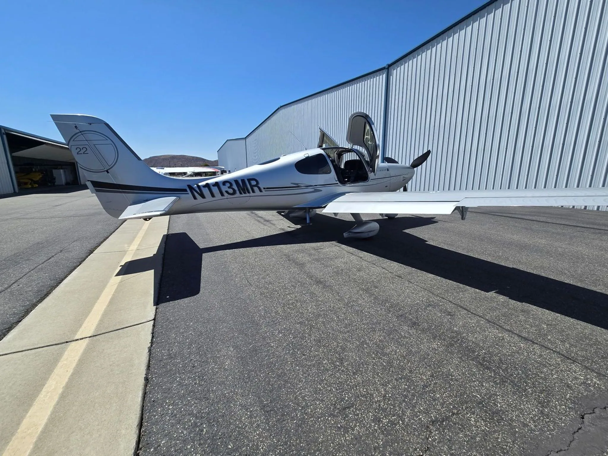


Free — save the SR22T to your watchlist and track it in one place.
More Cirrus SR22Tmanuals & documents
See all 21 →- Vantage 12 Pilot’s GuideV Speeds Reference
- Airworthiness Concern SheetAirworthiness Directives
- SERVICE BULLETIN HC-SB-30-390 Propeller - Spinner/Anti-ice Travel Tube InterferenceService Bulletins
- INSTRUCTIONS FOR INSTALLATION OF HARTZELL 4C1-F650A1/76C04(B)-0.6 PROPELLER ON CIRRUS SR22 AIRCRAFTMaintenance Manual
- INSTRUCTIONS FOR CONTINUED AIRWORTHINESS FOR HARTZELL 4C1-F650A1/76C04(B)-0.6 PROPELLER ON CIRRUS SR22T AIRCRAFTMaintenance Manual
- Supplemental Type Certificate SA03962ATSupplemental Type Certificate
- PILOT’S OPERATING HANDBOOK AND FAA APPROVED AIRPLANE FLIGHT MANUAL for the CIRRUS SR22Performance Data
- PILOT’S CHECKLIST SR22 G1 OR G2Checklist
- Continued Airworthiness Manual For Cirrus Design SR22 Series AirplanesMaintenance Manual
- Service Bulletin TAT SB10-01Service Bulletins
- Hartzell Engine Technologies Service Bulletin 033Service Bulletins
- SCHEDULE OF AIRWORTHINESS DIRECTIVESAirworthiness Directives
If you fly the Cirrus SR22T, you may also be researching these.




In this document
Electrical System Overview
This section outlines the main components of the electrical system in the Cirrus SR22T, including the battery, alternator, and various circuit breakers. It provides a high-level understanding of how power is distributed throughout the aircraft.
Wiring Layout
The wiring layout section includes detailed diagrams showing the routing of wires throughout the aircraft. It specifies wire types, colors, and gauge sizes, ensuring that technicians can accurately follow the wiring paths.
Component Connections
This section details the connections between various electrical components, such as avionics, lights, and sensors. It includes pin assignments and connector types, which are crucial for proper assembly and troubleshooting.
Safety notes
- Ensure all electrical connections are secure to prevent failures.
- Follow the wiring diagram closely to avoid incorrect installations.
Full document text
Document Number: 102NMAN0003 E JPREC PRECISE FLIGHT Essentials for Safety and Performance. 63354 POWELL BUTTE ROAD BEND, OR 97701, USA 800-547-2558 www.precsieflight.com Revision Number: Aircraft Serial Number: Instructions for Continued Airworthiness Cirrus SR22/SR22T Built-In Oxygen System STC Number SA01708SE NOTICE The Airworthiness Limitations Section (Section 2.0) is FAA Approved and specifies maintenance required under Sections 43.16 and 91.403 of the Federal Aviation Regulations, unless an alternative program has been FAA Approved. These documents must be kept with the aircraft records. THIS DOCUMENT CONTAINS PROPRIETARY INFORMATION OF THE PRECISE FLIGHT, INC. (PFI) COMPANY, AND ITS RECEIPT OR POSSESSION DOES NOT CONVEY ANY RIGHTS TO REPRODUCE, DISCLOSE ITS CONTENTS, OR TO MANUFACTURE, USE, OR SELL ANYTHING IT MAY CONTAIN OR DESCRIBE IN ANY WAY. REPORDUCTION, DISCLOSURE, OR USE WITHOUT SPECIFIC PRIOR WRITTEN CONSENT OF PFI IS STRICTLY PROHIBITED. FAA Approval Date:, MAR 10 2010 Page 1 of 41 JPR PRECISE PRECISE FLIGHT Essentials for Safety and Performance. 63354 POWELL BUTTE ROAD BEND, OR 97701 800-547-2558 www.preciseflight.com Document Number: 102NMAN0003 Revision Number: E INSTRUCTIONS FOR CONTINUED AIRWORTHINESS - STC SA01708SE Cirrus Design SR22/SR22T Built-In Oxygen System REVISION HISTORY Approved Rev. DESCRIPTION OF CHANGES Author Date By Approved Date - Original Release STP 9/7/2006 JNS 9/7/2006 A Revised document to include remote filler, and final oxygen system wire routing. JNS 9/27/2006 JNS 9/27/2006 FAA 10/3/2006 B JNS 4/27/2007 JNS/FAA 7/23/2007 C Revised document to include the A5 constant flowmeter, the Precise Flow Oxygen Conserver, added Section 2.7.1 inspection checklist for ease of maintenance, updated wire schematics adding the remote Annunciator option, added Section 3.0 IPC to this document for ease of maintenance for Cirrus Customers and Service Centers. Added section 2.4.7 for either ground or flight testing of the O2 Required Pressure Sensor, added a ground test procedure for sensor test, allowed the owner/pilot to perform the 50, 200, and 500hr inspections on the breathing equipment. Corrected typo on item 1, Figure 19 for the Bottle Assembly. Added Trouble Shooting Flow Charts figures 5-11. JNS 2/8/2008 JNS 2/8/2008 D Removed owner/pilot notes for 50, 200, and JNS 3/21/2008 JNS 3/21/2008 500hr inspections on the breathing equipment as required per the FAA. Corrected page numbering error do to formatting. E Updated ICA for Cirrus Perspective Installations; Added new SR22T model throughout document; changed Hydrostatic pressure test to every 5 yrs (was: 3 yrs); W. Ashforth 2/22/10 W. Adth 2/22/10 2102 2/23/10 Title Page Rights Apply FAA Approval Date: MAR 10 2010 Page 2 of 41 JPREC PRECISE FLIGHT Essentials for Safety and Performance. 63354 POWELL BUTTE ROAD BEND, OR 97701 800-547-2558 www.preciseflight.com Document 102NMAN0003 Number: Revision Number: E INSTRUCTIONS FOR CONTINUED AIRWORTHINESS - STC SA01708SE Cirrus Design SR22/SR22T Built-In Oxygen System TABLE OF CONTENTS Revision History. Table of Contents List of Active Pages. 1.0 Overview...... 1.1 Purpose..... 1.2 ICA Revisions 2.0 Instructions for Continued Airworthiness. 2.1 Introduction .......... 2.2 System Description...... 2.3 Special Tools Required. 2.4 Maintenance Instructions..... 2.4.1 Bottle Removal and Replacement.. 2.4.2 Filler Station Cleaning ..... 2.4.3 Line Cleaning.. 2.4.4 Functional Test. 2.4.5 Oxygen System Installation.......... 2.4.6 Oxygen System Bleed-Down (Purging) 2.4.7 Oxygen Required Pressure Calibration Check.. 2.4.7.1 Flight Test (Method A)......... 2.4.7.2 Ground Test (Method B) 2.5 Trouble Shooting Guide ...... 2.5.1 Oxygen System Fails to Operate 2.5.3 Additional Technical Assistance.... 2.5.2 Oxygen System Trouble Shooting Flow Chart. 2.6 Airworthiness Limitations 2.7 Scheduled Maintenance Intervals and Overhaul Intervals for Inspections for Continued Airworthiness...... 2.7.1 Scheduled Maintenance Checklist.. - End of Checklist - 2.8 System Wiring Diagram. 2.8 System Wiring Diagram 3.0 Illustrated Parts Catalog.... 3.1 Purpose...... 3.2 Overview. 3.3 Breathing Stations...... 3.3.1 Constant Flow Breathing Equipment 3.3.2 Precise Flow Demand Flow Breathing Equipment.. 3.4 Overhead Distribution Manifold Installation....... 3.5 Oxygen Low Pressure Line Installation... 3.6 Oxygen Bottle Installation 3.7 Display/Logic Assembly Installation 3.7.1 Display and Controller Installations - Standard Installation 3.7.2 Display and Controller Installations - Ribbon Cable......... 3.7.3 Display and Controller Installation - Cirrus Perspective... Title Page Rights Apply FAA Approval Date: MAR 10 2010 2 3 6 6 7 235666 7 7 9 9 9 10 10 10 11 11 11 12 12 15 15 15 20 21 22 22 23 26 27 30 30 30 30 30 32 33 34 34 36 36 37 38 Page 3 of 41 PRECIS PRECISE FLIGHT Essentials for Safety and Performance. 63354 POWELL BUTTE ROAD BEND, OR 97701 800-547-2558 www.preciseflight.com Document 102NMAN0003 Number: Revision Number: E INSTRUCTIONS FOR CONTINUED AIRWORTHINESS-STC SA01708SE Cirrus Design SR22/SR22T Built-In Oxygen System 3.7.4 OPTIONAL - Remote Annunciator (OPTIONAL) 3.8 Filler Port and Line Installation 39 40 Title Page Rights Apply FAA Approval Date: MAR 10 2010 Page 4 of 41 PRECIS PRECISE FLIGHT Essentials for Safety and Performance. 63354 POWELL BUTTE ROAD BEND, OR 97701 800-547-2558 www.preciseflight.com Document Number: 102NMAN0003 Revision Number: E INSTRUCTIONS FOR CONTINUED AIRWORTHINESS - STC SA01708SE Cirrus Design SR22/SR22T Built-In Oxygen System LIST OF ACTIVE PAGES ORIGINAL ADDED PAGES ORIGINAL ADDED PAGES PG REV PG REV PG REV PG REV PG REV PG REV PG REV PG REV 1 E E E 234567890 10 11 12 13 14 15 21 26762222222222235835386 16 17 18 19 20 E 24 E E E E 29 E 30 31 E E 34 E E E E 38 E 39 E 40 41 E шшшшшшшшшшшшшшшшшшшшшшшшшшшшшшшшшшшшшшшшш E E E E E E E E Title Page Rights Apply FAA Approval Date: MAR 10 2010 Page 5 of 41 JPREC PRECISE FLIGHT
Show full textShow less
Essentials for Safely and Performance. 63354 POWELL BUTTE ROAD BEND, OR 97701 800-547-2558 www.preciseflight.com Document Number: 102NMAN0003 Revision Number: E INSTRUCTIONS FOR CONTINUED AIRWORTHINESS - STC SA01708SE Cirrus Design SR22/SR22T Built-In Oxygen System 1.0 OVERVIEW 1.1 PURPOSE The Built-In Oxygen System ("Oxygen System" or "System"), is installed to provide supplemental oxygen for the pilot and passengers. The System consists of the following: 1. A 77 cu ft composite wrapped cylinder mounted in the aft fuselage of the aircraft 2. An oxygen regulator which is connected to the bottle and contains: a. An overpressure discharge 3. 456 b. A high pressure transducer A Remote Filler Assembly located in the aft center of the baggage compartment and contains: a. A service port for filling the Oxygen System b. A manual pressure gauge Associated plumbing and fittings A center console panel display and System actuation switch An overhead distribution manifold with low pressure transducer and integrated interior LED dome light 7. Breathing devices and flowmeters with cannulas, or masks Setting the oxygen switch to ON illuminates the display showing oxygen quantity and energizes the System to allow oxygen to reach the overhead distribution manifold. Additionally the System annunciates if oxygen should be used in the aircraft as well as oxygen pressure or electrical faults. Four (4) manually operated oxygen flowmeters can be connected to the oxygen distribution manifold. The flow controls are calibrated and adjustable for altitude by the user. The following flow controls can be one of the following: 0 0 A4 Flowmeters and Standard or Oxygen Conserving Cannulas -- Up to 18,000 Ft A4 Flowmeters and Masks (Standard and Microphone) -- Up to 25,000 Ft A5 Flowmeters and Standard or Oxygen Conserving Cannulas - Up to 18,000ft A5 Flowmeters and Masks (Standard and Microphone) - Up to 25,000 Ft Precise Flow Oxygen Conserver with Dual Lumen Cannula - Up to 18,000ft Precise Flow Oxygen Conserver with Masks (Standard and Microphone) - Up to 25,000ft 1.2 ICA REVISIONS To ensure the maintenance of your existing aircraft, possible revisions to Section 2.0 Instructions for Continued Airworthiness may require updating over the life of the aircraft. Per the applicable Federal Aviation Regulations, an update process is required to properly maintain these instructions in addition to the aircraft itself. Because of this, it is imperative to complete the registration card for the aircraft once the System has been installed. Revisions can be made by a service letter from Precise Flight Inc., an Airworthiness Directive as issued by the Administrator, by single page updates, or by a complete replacement of all pages of the manual. It must be clearly noted as to the revision level of the pages listed in the List of Active Pages. If a single sheet(s) is replaced, replace the List of Active Pages with the new one provided, or update the list manually and initial and date the list. Title Page Rights Apply FAA Approval Date: MAR 10 2010 Page 6 of 41 JPRE PRECISE FLIGHT Essentials for Safety and Performance. 63354 POWELL BUTTE ROAD BEND, OR 97701 800-547-2558 www.preciseflight.com Document Number: 102NMAN0003 Revision Number: E INSTRUCTIONS FOR CONTINUED AIRWORTHINESS - STC SA01708SE Cirrus Design SR22/SR22T Built-In Oxygen System 2.0 INSTRUCTIONS FOR CONTINUED AIRWORTHINESS 2.1 INTRODUCTION The contents of this section provide the instructions for continued airworthiness for the Cirrus SR22/SR22T Built-In Oxygen System. The majority of the installation does not affect the standard airworthiness of the aircraft; only the key Oxygen System items that exist different are noted in this section. All structure and general maintenance must be performed in accordance with existing approved maintenance practices, the aircraft maintenance manual or other FAA Approved document(s). 2.2 SYSTEM DESCRIPTION FWD CABIN LP OXYGEN LINE (ALUMINUM TUBING) GROUND STRAP FOR LIGHTNING PROTECTION CENTER CABIN LP OXYGEN LINE (ALUMINUM TUBING) OXYGEN SYSTEM DISPLAY CIRCUIT BREAKER TIE-IN- (SHARE WITH INTERIOR CABIN LIGHT CB) OXYGEN SYSTEM LOGIC CONTROLLER A AFT WIRE HARNESS (HIGH-PRESSURE TRANSDUCER AND SOLENOID WIRING) REMOTE OXYGEN SYSTEM FILLER PORT WITH PRESSURE GAUGE Figure 1 SR22/SR22T Built-In Oxygen System Overivew Title Page Rights Apply FAA Approval Date: MAR 10 2010 -NON-CONDUCTIVE HOSE FOR LIGHTNING PROTECTION AND EASE OF MAINTENANCE GROUND STRAP FOR LIGHTNING PROTECTION Page 7 of 41 JPREC PRECISE FLIGHT Essentials for Safety and Performance. 63354 POWELL BUTTE ROAD BEND, OR 97701 800-547-2558 www.preciseflight.com Document Number: 102NMAN0003 Revision Number: E INSTRUCTIONS FOR CONTINUED AIRWORTHINESS - STC SA01708SE Cirrus Design SR22/SR22T Built-In Oxygen System The Built-In Oxygen System consists of a few simple components for supplying sufficient oxygen to the crew and passengers of the Cirrus SR22/SR22T aircraft. These components follow: Oxygen Bottle Stores 77 cu ft of Oxygen at 1800 psig Regulator Assembly Converts the high bottle pressure to a usable 70 psig for cabin distribution. This is actuated through a latching solenoid assembly with an electrical connection to the aircraft cockpit. The regulator assembly allows the bottle to be filled through a separate fill port and a fill gage. The fill gage allows the maintenance personnel to monitor the fill operation. An overpressure burst disc is incorporated to dissipate excess pressure and protect the bottle. A high pressure transducer electrically transmits bottle pressure to the cockpit display. Oxygen Remote Filler Station - Allows for easy filling of the oxygen system and incorporates a manual pressure gage for filling, and preflight. Located for convenient access through the baggage door on the left hand side of the aircraft, just above the floor on the center of the baggage compartment aft wall. An easy access door covers the filler port to prevent damage to the filler from shifting baggage. Oxygen Distribution Lines and Electrical Wiring Connections The oxygen distribution lines allow oxygen to safely enter the aircraft cabin. The electrical connections allow the bottle and oxygen cabin pressure to be transmitted to the cockpit and for cockpit selection of oxygen in the aircraft cabin. Oxygen Distribution Manifold Allows the crew and passengers to connect to the Oxygen System with four (4) quick disconnect fittings with the capability of sealing oxygen flow to the cabin when disconnected. Oxygen System Display and Display-Logic Controller (DLA) - The Oxygen System display provides control over the oxygen delivery to the aircraft cabin. This display supports an Annunciator to indicate when oxygen is to be used (above 12,000 ft PA) and an indication of cabin oxygen or electrical actuation fault. The cabin oxygen flashing fault illuminates if cabin oxygen is not - between 60 psig and 85 psig. The electrical actuation fault illuminates if there is an electrical short or open circuit to the latching solenoid at the regulator. The oxygen controller supports these functions and ensures a short duration signal to drive the latching solenoid. Breathing Equipment The breathing equipment can consist of either constant flow and/or demand flow regulator breathing stations. Both use a connection to the distribution manifold. Precise Flight A4 or A5 constant flow devices or "Flowmeters" indicate the flow of oxygen with an integral valve to control the quantity of oxygen reaching the crew or passenger. The Precise FlowⓇ demand flow conservers are calibrated and adjusted by the user for altitude to supply oxygen to either dual lumen cannulas up to 18,000ft, or dual sensing masks. The flow indicator on this flow device is labeled with appropriate oxygen flow for increasing aircraft altitude. The constant flowmeter or demand regulator is attached to the appropriate approved mask or cannula to deliver oxygen to the crew or passengers. Title Page Rights Apply FAA Approval Date: MAR 10 2010 Page 8 of 41 JPR PRECISE PRECISE FLIGHT Essentials for Safety and Performance. 63354 POWELL BUTTE ROAD BEND, OR 97701 800-547-2558 www.preciseflight.com Document Number: 102NMAN0003 Revision Number: E INSTRUCTIONS FOR CONTINUED AIRWORTHINESS - STC SA01708SE Cirrus Design SR22/SR22T Built-In Oxygen System 2.3 SPECIAL TOOLS REQUIRED -Plastic reservoir hand pump -Chemical-resistant gloves -Protective eyewear with side shields Refer to the installation instructions, or drawings for the Precise Flight Built-In Oxygen System. 2.4 MAINTENANCE INSTRUCTIONS CAUTION: INSTALL PROTECTIVE COVERS ON ALL OPEN LINES AND COMPONENT FITTINGS IMMEADIATELY AFTER THEY ARE DISCONNECTED. Maintain aircraft structure and wiring in accordance with aircraft maintenance manual and FAA AC43.13. Precise Flight Inc., www.preciseflight.com, is the approved Overhaul Facility 2.4.1 BOTTLE REMOVAL AND REPLACEMENT The Built-In Oxygen System bottle removal and replacement procedure follows: WARNING: OXYGEN SYSTEM MUST BE BLED TO ZERO PSI BEFORE ANY MAINTENANCE. Bleeding Procedure: 1. Aircraft battery power ON, oxygen display panel ON. 2. Connect Flowmeter breathing device to overhead distribution panel and turn Flowmeter to full flow until oxygen is purged from the System and the flashing red 200 PSI quantity LED has been illuminated for 10 minutes and no more oxygen is flowing through the breathing device. 3. Oxygen panel display OFF, aircraft power OFF. Bottle Removal Procedure: 1. Remove aft fuselage access panel fasteners. 2. Remove and store access panel in a safe location. 3. Detach flexible oxygen line and cap both lines. 4. Disconnect electrical harness. 5. Release the two band clamp restraints. 6. Remove bottle and regulator assembly by first moving the assembly forward and to the left. Remove bottle and regulator assembly aft end of the bottle first. 7. Installation is opposite of removal - Tighten wing nuts until snug and then two more turns to ensure proper tension on clamp bolt. 8. Perform a functional system check following installation (purging per next step can be accomplished during the functional test). 9. Purge the oxygen system by filling the main tank to a minimum of 500psig and bleeding the system down between 50-100psig by following the bleeding procedure prior to filling the system for use. Title Page Rights Apply FAA Approval Date: MAR 10 2010 Page 9 of 41 JPREC PRECISE FLIGHT Essentials for Safety and Performance. 63354 POWELL BUTTE ROAD BEND, OR 97701 800-547-2558 www.preciseflight.com Document Number: 102NMAN0003 Revision Number: E INSTRUCTIONS FOR CONTINUED AIRWORTHINESS - STC SA01708SE Cirrus Design SR22/SR22T Built-In Oxygen System 2.4.2 FILLER STATION CLEANING The filler port requires cleaning periodically, and prior to filling, to keep clean of dirt, dust, and oils to prevent fire. 2.4.3 LINE CLEANING Line Cleaning Procedure: 1. Preparation a. Obtain a suitable container for collecting fluid waste. b. Wear protective gloves and eyewear. c. Assemble a reservoir pump and drain line, see Fig 1. 2. Flushing a. Fill 2 qt reservoir with 1% Alconox or Liquinox detergent solution. www.alconox.com b. Attach reservoir pump to cabin oxygen line. c. Pump 2 qt Alconox or Liquinox through oxygen line. d. Undo pump connection and rinse pump with clear water. e. Fill 2 qt reservoir with clear tap water. f. Attach reservoir pump to cabin oxygen line. g. Pump 2 qt water through oxygen line. h. Repeat steps A through D, rinsing the pump with the next cleaning material. i. Pump 1 qt Methyl Alcohol through oxygen line. j. Pump 1 qt ASAHIKLIN AK-225 through oxygen line. www.agcchem.com k. Purge the line of AK-225 by passing clean dry air through the line. 1. With the air still flowing, sniff the air exiting the drain line. The absence of odors will verify the line is free of AK-225. m. Reconnect lines and restore System to service. 2.4.4 Functional Test The following test procedure will evaluate the Built-In Oxygen System installation in the aircraft: 1. Check wiring and connections before applying aircraft battery power. 2. Fill Oxygen System with aviators oxygen (see Maintenance Manual or Flight Manual Supplement), leave access panel open. 3. Switch the Oxygen System ON at the oxygen control panel and verify that the Oxygen System quantity display indicates the same oxygen pressure shown at the aft fill port gauge. 4. Connect Flowmeter breathing device to overhead distribution panel. 5. Ensure oxygen flow through a breathing device. 6. Switch the Oxygen System OFF at the oxygen control panel. 7. Turn aircraft battery power off. FAA Approval Date:, Title Page Rights Apply MAR 10 2010 Page 10 of 41 JPRECI PRECISE FLIGHT Essentials for Safety and Performance. 63354 POWELL BUTTE ROAD BEND, OR 97701 800-547-2558 www.preciseflight.com Document Number: 102NMAN0003 Revision Number: E INSTRUCTIONS FOR CONTINUED AIRWORTHINESS - STC SA01708SE Cirrus Design SR22/SR22T Built-In Oxygen System 2.4.5 Oxygen System Installation Refer to Precise Flight Inc. drawing list 102N0000 Cirrus Design Built-In Oxygen System for installation and removal of the oxygen system components. 2.4.6 Oxygen System Bleed-Down (Purging) Use the following procedure to bleed-down the oxygen system should any of the hard lines, non- conductive line be opened, or bottle removed and re-installed/replaced. This procedure is required to prevent contamination, or moisture inside the system. 1. Attach the filler line to the filler port, making sure to purge the line prior to attaching to the aircraft. 2. With the System ON, and flowmeters (or open Connectors) installed in the distribution ports, initiate flow for 1-2min. 3. Removed the flowmeters from the distribution port, and turn the oxygen System OFF, and fill to 650psig. 4. Perform leak checks as required. 5. Turn the System ON and using flowmeters (or open connectors) installed in the distribution ports; bleed the system down to below 50psig (but above Opsig). 6. Repeat steps 3-5 once. (Leak check not required on second purge) 7. Removed the flowmeters from the distribution port, and turn the oxygen System OFF, and fill to 1500psig. 8. Perform Final leak check. 9. Fill System to 1800-2000psig as required. 2.4.7 Oxygen Required Pressure Calibration Check The Precise Flight, Inc. Fixed Oxygen System is designed with an additional safety feature to indicate O2 is required if the system is off, or there is no pressure at the outlet, when the cabin pressure is at 12,000ft Pressure Altitude (PA). This pressure sensor is internal to the Display Logic Controller (DLA). To ensure this safety feature is functioning properly a check of its function is required during the annual inspection. This may be done by a flight test to altitude, or by a ground test. Note: Note: The Altitude Sensor in the Oxygen System Display Logic Assembly is NOT connected to the aircraft static system. Not All aircraft are equipped with a Display Logic Assembly where a test port is available. In these cases the flight test is the only approved method for testing the calibration. Title Page Rights Apply FAA Approval Date: MAR 10 2010 Page 11 of 41 JPRECI PRECISE FLIGHT Essentials for Salety and Performance. 63354 POWELL BUTTE ROAD BEND, OR 97701 800-547-2558 www.preciseflight.com Document Number: 102NMAN0003 Revision Number: E INSTRUCTIONS FOR CONTINUED AIRWORTHINESS - STC SA01708SE Cirrus Design SR22/SR22T Built-In Oxygen System 2.4.7.1 Flight Test (Method A) Method A of checking the calibration is by flight test. This flight is intended to be done during the maintenance release flight following the annual inspection. The procedure is to fly to 11,000ft PA (alt setting of 29.92inHg) and during the climb to 12,500ft PA with the oxygen system OFF, note the altitude which the O2 Required Amber light begins to flash. This should occur between 11,500ft PA and 12,500ft PA if the system is operating normally. 2.4.7.2 Ground Test (Method B) Method B for checking the calibration is by ground test. The ground test requires the removal of pilots side Aft Trim Panel to gain access to the Display Logic it Controller (DLA), and is recommended that this be performed with the seats removed, and the LH (Pilots) side Aft Trim Panel must be removed. Note: This should be performed during the Cabin Group Inspection as part of the Annual inspections. In the case of a progressive Maintenance Program, this test should be accomplished as close to once every year, not to exceed 18months. Use the flowing procedure for the ground test method for the DLA pressure calibration check: 1. Remove the Pilot Seat if not already removed as part of the annual maintenance check, cabin group. 2. Remove the LH Aft Trim Panel if not already removed as part of the annual maintenance check, cabin group to gain access to the DLA. (See Figure 2) OXYGEN DISPLAY - CENTER CONSOLE DUST COVER PLUG DISPLAY LOGIC ASSEMBLY (100N2020-3) Figure 2- Location of Oxygen System Display Logic Controler 3. Check general condition of the wiring, and DLA. 4. Remove the Dust Cover/Plug. (See Figure 3) Title Page Rights Apply FAA Approval Date: MAR 10 2010 Page 12 of 41 JPREC PRECISE FLIGHT Essentials for Salety and Performance. 63354 POWELL BUTTE ROAD BEND, OR 97701 800-547-2558 www.preciseflight.com Document Number: Revision Number: 102NMAN0003 E INSTRUCTIONS FOR CONTINUED AIRWORTHINESS-STC SA01708SE Cirrus Design SR22/SR22T Built-In Oxygen System DISPLAY LOGIC- ASSEMBLY (100N2020-3) PRY OUT- PLUG PRESSURE SENSOR Figure 3 Removal of the Dust Cover Plug 5. Using a soft rubber or simulate tube with and Inside Diameter (ID) of 7/16in, connect one end to the pressure sensor nipple, and the other to the static line on a Pitot-Static Test system with pump. DISPLAY LOGIC ASSEMBLY (100N2020-3) TUBING, 07/16 INSIDE DIAMETER PRESSURE SENSOR TO TEST EQUIPMENT Figure 4- Attachment of the Static Test Hose CAUTION: CARE MUST BE TAKEN DURING THE INSTALLATION AND REMOVAL OF THE 7/16DIA INSIDE DIAMETER TUBING TO PREVENT DAMAGE TO THE SENSOR AND/OR THE CONTROLER CIRCUIT. DO NOT YANK, OR PULL EXCESSIVLY DURING THE REMOVAL OR DAMAGE WILL OCCUR AND THE UNIT MUST BE REPLACED. 6. With the aircraft in a safe condition to power up the Main Bus 2, turn ON the main bus 2 with the oxygen system off. 7. Cycle the system ON and OFF to ensure the system is functioning, use a breathing device to ensure flow is present. With the system OFF, let the oxygen 'bleed down' prior to removing the breathing device. Title Page Rights Apply FAA Approval Date: MAR 10 2010 Page 13 of 41 PRECIS PRECISE FLIGHT Essentials for Safety and Performance. 63354 POWELL BUTTE ROAD BEND, OR 97701 800-547-2558 www.preciseflight.com Document Number: 102NMAN0003 Revision Number: E INSTRUCTIONS FOR CONTINUED AIRWORTHINESS - STC SA01708SE Cirrus Design SR22/SR22T Built-In Oxygen System 8. Using the static portion of the Pitot-Static tester, increase the static altitude slowly to 11,000ft PA. Continue increasing the altitude and note when the display indicates "O2 required" as signified on the display by the flashing amber LED. Note the altitude which this occurred. 9. Verify the altitude where the indication first occurred: a. If indication is between 11,500ft PA and 12,500ft PA, then proceed to the next step. b. If the indication is outside of this range, re-verify the indication. If the DLA fails a second time, remove the DLA and replace, or contact PFI for re-adjustment. 10. Turn Aircraft power off. 11. Remove the pressure tubing taking extra care not to damage the DLA pressure transducer. 12. Re-install the dust cover/plug. 13. Note passing test as required. Title Page Rights Apply MAR 10 2010 FAA Approval Date:, Page 14 of 41 JPREC PRECISE FLIGHT Essentials for Safety and Performance. 63354 POWELL BUTTE ROAD BEND, OR 97701 800-547-2558 www.preciseflight.com Document Number: 102NMAN0003 Revision Number: E INSTRUCTIONS FOR CONTINUED AIRWORTHINESS - STC SA01708SE Cirrus Design SR22/SR22T Built-In Oxygen System 2.5 TROUBLE SHOOTING GUIDE 2.5.1 Oxygen System Fails to Operate a. Check circuit breaker. b. Check connector plugs for security and contact insertion. C. Check wiring diagram against aircraft installation. See Section 2.8. d. Check the system function per section 2.5.2. 2.5.2 Oxygen System Trouble Shooting Flow Chart This section is for reference when troubleshooting the PFI Fixed Oxygen System, if used, and parts returned, please copy steps taken for reference. CAUTION: Pressures above 105psig on the Low-Pressure side will damage the Low-Pressure Transducer and will Require the Transducer to be Replaced. Installation Complete, Purging and Leak Check Complete. System Fully charged for Service Turn ON Aircraft Power Cycle Aircraft Power or Cycle Oxygen System CB Turn ON Oxygen System Re-Fill Oxygen System to Over 1500psig No Light OFF System Turns ON and Fault Light (OFF or ON/ Blinking) Steady or Yes Blinking Fault Light Blinking Verify Oxygen Quantity is Greater than 700psig Yes 3 Steady 2 Figure 5-Trouble Shooting FlowChart (6) Title Page Rights Apply FAA Approval Date: MAR 10 2010 Page 15 of 41
What's in the Cirrus SR22T TCDS
A Type Certificate Data Sheet (TCDS) is the FAA's record of what an aircraft type was approved as. It is the source of truth for weights, seating, fuel and the rules the design was certified against. Expand any line to see what it means.
1,001 Cirrus SR22T parts for sale
See all →
Parts listed for sale by vetted eBay sellers — confirmed on eBay at checkout.