SERVICE BULLETIN M20-335D
Mooney M20J 201 · Service Bulletins
Overview
This service bulletin, M20-335D, issued by Mooney International Corporation, addresses a potential flight control balance issue that may arise after painting by external vendors. It specifically applies to several Mooney aircraft models, including the M20R, M20TN, M20U, and M20V, detailing the necessary steps for compliance. The bulletin emphasizes the importance of balancing the rudder and elevator control surfaces to ensure safe flight operations. Compliance is mandatory and involves a one-time inspection and potential adjustments to the control surfaces. The document provides detailed instructions for installation of limitation placards, checking flight control balance, and adding or replacing weights as necessary. It also outlines the return-to-service procedures and warranty information for labor associated with the compliance work.
- Compliance with this bulletin is mandatory for safety.
- Affected models include M20R, M20TN, M20U, and M20V.
- Maximum aircraft speed during compliance is 127 KIAS.
- Rudder weight limits: Max 3.85 lbs, Min 3.20 lbs.
- Elevator weight limits: Max 4.22 lbs, Min 4.00 lbs.
Document
Source
Originally published by www.mooney.com. Sprinkle hosts a reference copy with an added summary, specifications and searchable full text.
Document details
- Type
- Service Bulletins
- Year
- 2019
- Pages
- 41
- File size
- 1.5 MB
- Publisher
- www.mooney.com
Common. Rarer than 24% of the aircraft models we track.
Most owners only have the POH. Here's the essential set for the Mooney M20J 201.
- Pilot's Operating Handbook / AFM
- Checklist
- Maintenance Manual
- Parts Catalog (IPC)
- Systems & Wiring
- Service Bulletins
- Type Certificate (TCDS)
Mooney M20J 201 for sale now


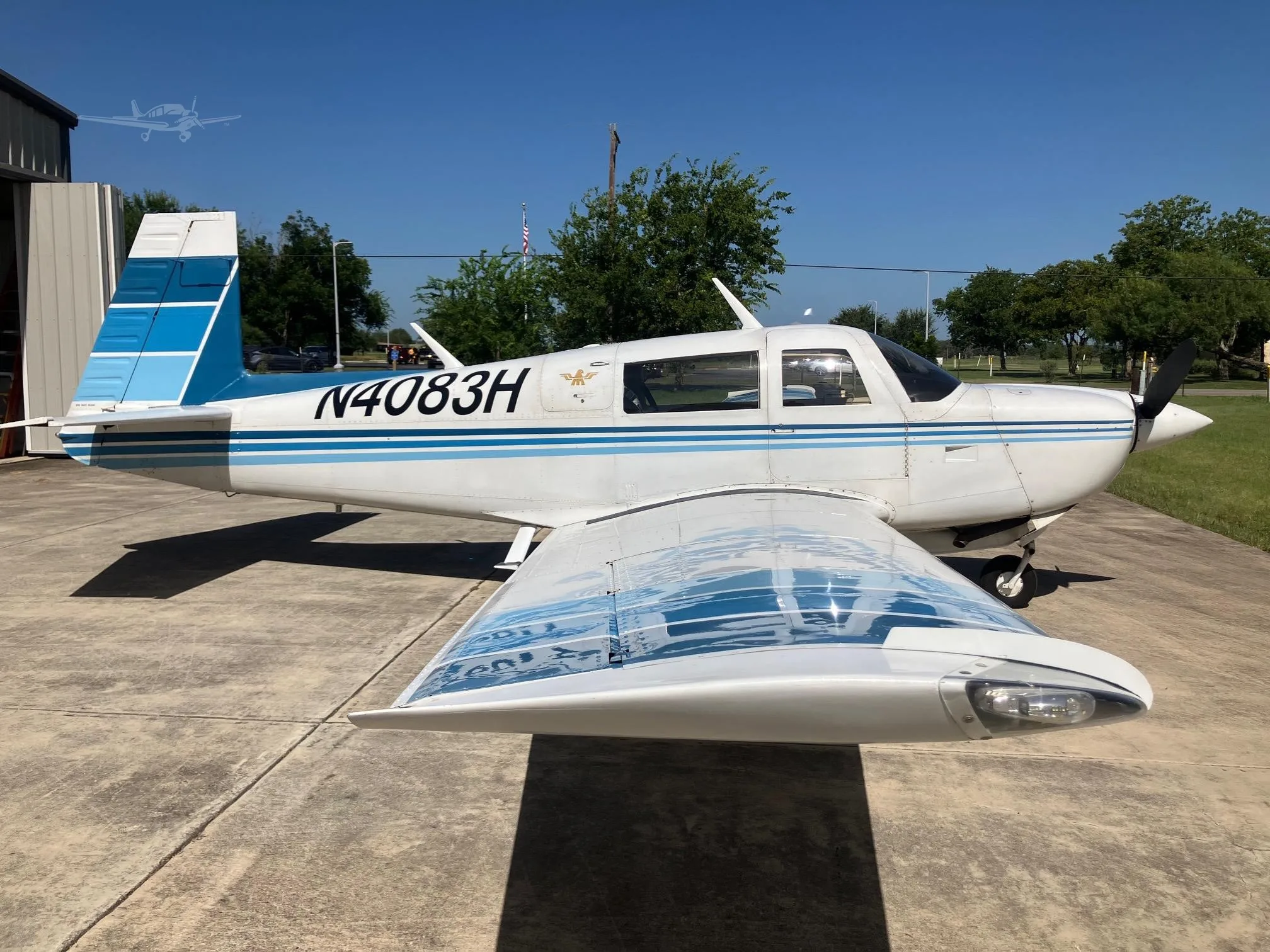
Free — save the M20J 201 to your watchlist and track it in one place.
More Mooney M20J 201manuals & documents
See all 18 →- Form 2.59c M20J N5760R Emergency Checklist – Version 5 2014/10/29Checklist
- Aircraft Design: A Systems Engineering ApproachPerformance Data
- SERVICE BULLETIN M20-313AService Bulletins
- SERVICE BULLETIN M20-314AService Bulletins
- SPECIAL AIRWORTHINESS INFORMATION BULLETIN SAIB: NE-08-26R3Airworthiness Directives
- AAIB Bulletin: 4/2010Maintenance Manual
- Advisory Circular Subject: Towbar and Towbarless Movement of AircraftEmergency Procedures
- SERVICE BULLETIN M20-282-AAvionics Manual
- SCHEDULE OF AIRWORTHINESS DIRECTIVESAirworthiness Directives
- INSTALL MOONEY 201 (M20J) SPINNERS ON EARLIER MODEL MOONEYSWeight And Balance
- PILOT'S OPERATING HANDBOOK AND FAA APPROVED AIRPLANE FLIGHT MANUAL MOONEYPilot's Operating Handbook
- Mooney M20J 2900 POUND GROSS WEIGHT INCREASE, RETROFIT KITSWeight And Balance
If you fly the Mooney M20J 201, you may also be researching these.
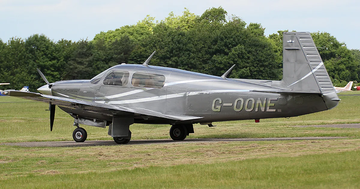


In this document
Introduction
Mooney International Corporation has identified a potential flight control balance issue that may occur after painting by outside vendors. The bulletin outlines the aircraft models affected and the necessary steps to ensure compliance with Mooney specifications for control surface balancing.
Instructions
The bulletin provides detailed instructions for the installation of limitation placards, checking the balance of the rudder and elevator, and procedures for adding or replacing weights if necessary. It emphasizes the importance of following the steps in sequence and recording all surface rigging values before disassembly.
Compliance and Return to Service
After completing the required inspections and adjustments, the aircraft must be returned to service following the outlined procedures. This includes verifying the full travel and proper rigging of flight controls, checking the operation of the tail strobe, and submitting compliance documentation to Mooney International Corporation.
Weight Limits
The bulletin specifies weight limits for the rudder and elevator control surfaces. For the rudder, the maximum weight limit is 3.85 lbs and the minimum is 3.20 lbs. For the elevator, the maximum weight limit is 4.22 lbs and the minimum is 4.00 lbs.
Safety Notes
Cautions are included regarding the handling of control surfaces and weights, emphasizing the need for proper personal protective equipment when working with lead weights. Additionally, care must be taken to avoid exceeding the maximum aircraft speed of 127 KIAS during operations.
Safety notes
- Do not exceed speeds indicated on installed placard.
- Use proper handling techniques for lead weights, including PPE.
- Avoid moving control surfaces to extreme angles during inspection.
Full document text
SERVICE BULLETIN SERVICE BULLETIN M20-335D Date: May 2, 2019 THIS BULLETIN DOES NOT CHANGE AIRCRAFT TYPE DESIGN MOONEY INTERNATIONAL 165 Al Mooney Road North Kerrville, Texas 78028 CORPORATION SBM20-335D Page 1 MOONEY INTERNATIONAL CORPORATION 165 Al Mooney Road North, Kerrville, Texas 78028 tel: 830-896-6000 www.mooney.com SUBJECT: Mooney Aircraft Flight Control Balancing After Painting [ Chapter 27 - FLIGHT CONTROLS] MODELS/ SN M20R - S/N 29-0520 thru 29-0525 AFFECTED: M20TN - S/N 31-0128 thru 31-0143 M20U - S/N 32-0002, 32-0003 M20V - S/N 33-0004, 33-0006, 33-0007 TIME OF Before Next Flight COMPLIANCE: INTRODUCTION: Mooney International Corporation has determined a flight control balance issue may exist after final paint by outside vendors. Mooney Engineering has determined that the aircraft listed will need to have the specified control surfaces removed and balanced per Mooney specifications found in the applicable Service and Maintenance Manual and Mooney Spec 20 Section 35. If Rudder and/or Elevator Control Surface is found to be out of specification, you will need to use STEPS 3.0 in this Service Bulletin. A Limitation Placard must be installed prior to flight for Aircraft requiring flights to a maintenance facility. Compliance with this Service Bulletin will be considered a one-time inspection and repair, requiring no additional inspections, unless flight control(s) are repaired, replaced or repainted, which will then need to be rebalanced as required. INSTRUCTIONS: Read entire procedures before beginning work. NOTE: Record ALL Surface Rigging Values before removing components. Run trim wheel up, all the way to the stop before removing components. - CAUTION - DO NOT move control surfaces to extreme angles. Be gentle with tabs and do not bend them. STEP 1 - LIMITATION Placard (for Aircraft requiring flights to a maintenance facility) 1.0 PLACARD INSTALLATION - Refer to Figure SBM20-335-1 1.1. Install placard P/N M20-335-901 or M20-335-902 on instrument panel, refer to Figure SBM20-335-1 for effectivity, clean surface area with isopropyl alcohol before applying placard, this will remove any oils or debris from surface. 1.2. Fly Aircraft to approved Mooney Repair Station for compliance with this Service Bulletin. - CAUTION - DO NOT EXCEED SPEEDS INDICATED ON INSTALLED PLACARD SBM20- 335- 901 OR SBM20-335-902. STEP 2 - Checking Flight Control Balance - Rudder and Elevator Only RUDDER REMOVAL/INSTALLATION - Refer to Figure SIM20-335-2 2.1. Disconnect rudder push- pull tube from rudder horn by removing Bolt AN3-10, Washers NAS1149F0332P, Nut MS17825-3 and Cotter Pin MS24665-151, refer to Figure SIM20-335-2. 2.2. Disconnect (un-pin) Strobe Light harness from lower tailcone/rudder area. 2.3. Remove attaching hardware at rudder hinges, note each hinge hardware on zone chart(s) Figure SIM20-335-8. SERVICE BULLETIN SERVICE BULLETIN M20-335D Date: May 2, 2019 THIS BULLETIN DOES NOT CHANGE AIRCRAFT TYPE DESIGN MOONEY INTERNATIONAL 165 Al Mooney Road North Kerrville, Texas 78028 CORPORATION SBM20-335D Page 2 MOONEY INTERNATIONAL CORPORATION 165 Al Mooney Road North, Kerrville, Texas 78028 tel: 830-896-6000 www.mooney.com 2.4. Secure and stow control rods to prevent damage to painted skins. 2.5. Remove rudder by pulling it straight aft. 2.6. Balance rudder to specifications found in Chapter 27- 91- 00 of the applicable Mooney Service and Maintenance Manual and Mooney Spec 20 Section 35, be sure to install all static wicks and Strobe Light (if removed). 2.7. Fill out Flight Control Balance Sheets from Figures SIM20-335-9 and SIM20-335-10 for balance criteria. 2.8. If Balance is within Specifications, continue to STEP 2.10. 2.9. If Balance is NOT within Specifications, continue to STEP 3 - Adding or Replacing Weight.. 2.10. Re- Install IN reverse sequence as removed, refer to Chapter 5 in the applicable Service and Maintenance Manual for hardware torque values. Refer to Rudder Hinge Zone chart Figure SIM20-335-8 for stack- up of hardware (use new nuts and cotter pins upon reassembly). ELEVATOR REMOVAL/INSTALLATION - Refer to Figure SIM20-335-2 NOTE: It may be feasible to use a roll of duct tape to hold the Elevator at a slight angle, to aid the removal of hardware. Damage could occur if extending Elevator at extreme angles. NOTE: Keep Control Yoke from moving in/out with a piece of PVC or suitable tube, as damage could occur if control rod assembly snags on painted skins. 2.11. Disconnect elevator push pull tubes, by removing removing Bolt AN3-10, Washers NAS1149F0332P, Nut MS17825-3 and Cotter Pin MS24665-151, refer to Figure SIM20-335-2. 2.12. Remove bolts, nuts and washers from the four attaching hinges, note each hinge hardware on zone chart(s) LH Figure SIM20-335-6 and RH Figure SIM20-335-7 as required., refer to Figure SIM20-335-2. 2.13. Remove both elevators by pulling it straight aft. 2.14. Balance elevators to specifications found in Chapter 27- 91- 00 of the applicable Mooney Service and Maintenance Manual and Mooney Spec 20 Section 35, be sure to install static wicks (if removed). 2.15. Fill out Flight Control Balance Sheets from Figures SIM20-335-9 and SIM20-335-10 for balance criteria. 2.16. If Balance is within Specifications, continue to STEP 2.18. 2.17. If Balance is NOT within Specifications, continue to STEP 3 - Adding or Replacing Weights. 2.18. Re- Install IN reverse sequence as removed, refer to Chapter 5 in the applicable Service and Maintenance Manual for hardware torque values. Refer to Elevator Hinge Zone chart(s) LH Figure SIM20-335-6 and RH Figure SIM20-335-7 for stack- up of hardware (use new nuts and cotter pins upon reassembly). SERVICE BULLETIN SERVICE BULLETIN M20-335D Date: May 2, 2019 THIS BULLETIN DOES NOT CHANGE AIRCRAFT TYPE DESIGN MOONEY INTERNATIONAL 165 Al Mooney Road North Kerrville, Texas 78028 CORPORATION SBM20-335D Page 3
Show full textShow less
MOONEY INTERNATIONAL CORPORATION 165 Al Mooney Road North, Kerrville, Texas 78028 tel: 830-896-6000 www.mooney.com STEP 3 - Adding or Replacing Weights on Rudder and/or Elevator Flight Control NOTE: It may be required to slightly file (with rasp) control weight(s) to fit in flight control slot. CAUTION: Use Proper Handling of Lead Control Weight(s) Personal Protective Equipment (PPE) gloves, non- per- meable clothing and approved respirators are recommended. 3.1. Contact Mooney Product Support for details on adding weight. Adding weight to Rudder (Top Weight Only): WEIGHT LIMIT (LBS) MAX = 3.85 AND MIN = 3.20 3.2a. Remove factory counterweight from Rudder by, removing (8) NAS623- 3- 1 screws (keep for reassembly, refer to Figure SIM20-335-3. 3.2b. Add additional weight(s) 430055-003 as required, based on STEP 2 - Checking Flight Control Balance, match them to end of factory weight and drill (2) .203” .010” diameter thru added weights at a depth of .41” into end of factory counterweight as required, refer to Figure SIM20-335-3. Drill slowly and use care when drilling weight to prevent drill bit breakage. The use of “Boelube”, “Wax” or “Soap” is recommended on drill bit to prevent breakage. 3.2c. Install (2) Helicoil inserts MS51830-201L or R1191-3 to both newly drilled holes in counterweight. Use Loctite 271 on helicoil inserts when installing. 3.2d. Temporarily install added weight(s) 430055-003 with (2) MS35207-XXX to new holes in factory counter weight and Install counterweight to elevator with (6) NAS623- 3- 1 screws, hand tighten only and balance per instruction in STEP 2 - Checking Flight Control Balance 3.2e. When balance has been verified and within tolerance as specified in Mooney Service Manual and Mooney Spec 20 Section 35, Install added weight(s) and correct length screws to holes in factory counterweight, Using Loctite 222 on screws, hand tighten only. DO NOT OVER TIGHTEN, doing so will pull helicoil inserts from weight. 3.2f. Install counterweight to Rudder with (8) NAS623- 3- 1 screws, hand tighten only. DO NOT OVERTIGHTEN, doing so will pull helicoil inserts from weight. 3.2g. Touch-up paint as required, per Mooney Service and Maintenance Manual Chapter 20, refer to Aircraft paint kit for color(s), contact Mooney Service Parts for availability. 3.2h. Install Rudder per STEP 2 - Checking Flight Control Balance Installing new weight to Elevator (LH/RH): WEIGHT LIMIT (LBS) MAX = 4.22 AND MIN = 4.00 3.3a. Remove factory counterweight from Elevator by, removing (6) NAS623- 3- 1 screws (keep for reassembly, refer to Figure SIM20-335-4. 3.3b. Temporarily install new weight 430055- 501 to Elevator with (6) NAS623-3-1, hand tighten only. DO NOT OVERTIGHTEN, doing so will pull helicoil inserts from weight. 3.3c. Balance per STEP 2 - Checking Flight Control Balance, if balancing needs material to be removed from factory counterweight, continue to STEP 3.3d, if balance is within tolerance continue to STEP 3.3e. 3.3d. Clamp the lead weight in a vice and use a rasp to trim the cone end of the weight until it weighs the specific number from the balance check per STEP 2 - Checking Flight Control Balance, 3.3e. Install counterweight to Elevator with (6) NAS623- 3- 1 screws, hand tighten only. DO NOT OVERTIGHTEN, doing so will pull helicoil inserts from weight. 3.3f. Touch-up paint as required, per Mooney Service and Maintenance Manual Chapter 20, refer to Aircraft paint kit for color(s), contact Mooney Service Parts for availability. 3.3g. Install elevator(s) per STEP 2 - Checking Flight Control Balance SERVICE BULLETIN SERVICE BULLETIN M20-335D Date: May 2, 2019 THIS BULLETIN DOES NOT CHANGE AIRCRAFT TYPE DESIGN MOONEY INTERNATIONAL 165 Al Mooney Road North Kerrville, Texas 78028 CORPORATION SBM20-335D Page 4 MOONEY INTERNATIONAL CORPORATION 165 Al Mooney Road North, Kerrville, Texas 78028 tel: 830-896-6000 www.mooney.com STEP 4 - Return Aircraft To Service 4.0 RETURN TO SERVICE - Refer to the applicable Service and Maintenance Manual 4.1. Inspect flight controls for full travel, proper rigging, free- play, binding, security of mounting, proper lubrication and proper direction of control surface movement with relation to control wheel movement, refer to Chapter 27 of the applicable Service and Maintenance Manual. 4.2. Check tail strobe operation. 4.3. Confirm level flight, refer to Chapter 27 of the applicable Service and Maintenance Manual. 4.4. Send all Flight Control Balance Sheets from Figures SIM20-335-9 and SIM20-335-10, email to support@mooney.com for aircraft records. 4.4. Remove Placard M20-335-901 or M20-335-902 from Instrument Panel. NOTE: Fill out compliance card and send by MAIL or FAX to Mooney International Corporation as indicated on the attached Compliance Card. (See Figure SBM20-335-11). 4.5. Return aircraft to service. 4.6. Procedure complete. WARRANTY: Mooney International Corporation will warrant labor 8 hours in accordance with procedures of this Service Bulletin for aircraft currently covered under the Mooney International Corporation factory warranty program. Mooney International Corporation will warrant labor 2 additional hours per Flight Control requiring balancing in accordance with procedures of this Service Bulletin for aircraft currently covered under the Mooney International Corporation factory warranty program. REFERENCE 1. Applicable Mooney Service and Maintenance Manual DATA: 2. Product Support email: support@mooney.com or phone: 830-792-2919 3. Applicable Mooney Illustrated Parts Catalog 4. Mooney Spec 20 Section 35 (attached) PARTS LIST: Mooney International Corporation, Service Bulletin Parts Kit(s): Not Ordered As Kit Order parts as required below: Item P/N Description Qty 1. M20-335-901 Placard (for M20R and M20TN) 1 2. M20-335-902 Placard (for M20U and M20V) 1 3. 430055-003 Weight Bar (as required to Balance Rudder Assembly) A/R 4a. MS51830-201L Helicoil Insert (Mounting added rudder weight) 2 4b. R1191-3 (Alternate P/N) Helicoil Insert (Mounting added rudder weight) 2 5. MS35207-XXX Screw 10-32 x (XXX=Length determined by # weights) A/R (Shop Supplied Hardware) 6. 430055-501 Weight, Elevator (file as required for Balance) 1 7. 222 Loctite, Low Strength (Shop Supplied) AR 8. 271 Loctite, Permanent (Shop Supplied) AR SERVICE BULLETIN SERVICE BULLETIN M20-335D Date: May 2, 2019 THIS BULLETIN DOES NOT CHANGE AIRCRAFT TYPE DESIGN MOONEY INTERNATIONAL 165 Al Mooney Road North Kerrville, Texas 78028 CORPORATION SBM20-335D Page 5 MOONEY INTERNATIONAL CORPORATION 165 Al Mooney Road North, Kerrville, Texas 78028 tel: 830-896-6000 www.mooney.com LIMITATION: MAXIMUM AIRCRAFT SPEED 127 KIAS LIMITATION: SPEED 127 KIAS MAXIMUM AIRCRAFT PLACARD M20-335-902 PLACARD M20-335-901 NOTE: CLEAN SURFACE WITH ISOPROPYL ALCOHOL BEFORE APPLYING PLACARD NOTE: CLEAN SURFACE WITH ISOPROPYL ALCOHOL BEFORE APPLYING PLACARD M20R and M20TN Models M20U and M20V Models Figure SBM20-335-1 - PLACARDS, INSTRUMENT PANEL SERVICE BULLETIN SERVICE BULLETIN M20-335D Date: May 2, 2019 THIS BULLETIN DOES NOT CHANGE AIRCRAFT TYPE DESIGN MOONEY INTERNATIONAL 165 Al Mooney Road North Kerrville, Texas 78028 CORPORATION SBM20-335D Page 6 MOONEY INTERNATIONAL CORPORATION 165 Al Mooney Road North, Kerrville, Texas 78028 tel: 830-896-6000 www.mooney.com DETAIL E DETAIL F SEE NOTE USE AN960-10 AND/OR AN960-10L BETWEEN HINGE BLOCKS TO ELIMINATE POSSIBLE GAPS AND END PLAY. NAS1149F0332P MS21045-L3 NAS1149C0332R AN3-7A NAS1149F0332P MS21045-L3 NAS1149F0332P AN3-11A WASHER WASHER BOLT NUT WASHER NUT WASHER BOLT SEE NOTE NAS1149F0332P MS21045-L3 NAS1149F0332P AN3-11A NUT WASHER WASHER BOLT DETAIL D DETAIL G SEE NOTE NAS1149F0332P NAS1149F0332P AN3-11A NOTES: NAS1149F0363P THICK WASHER SAME AS AN960- 10 NAS1149F0332P THIN WASHER SAME AS AN960- 10L WASHER NAS1149F0332P WASHER NAS1149F0363P MS21045-L3 NUT WASHER WASHER BOLT ROLL OF TAPE TAIL STROBE HARNESS ELEVATOR PUSH PULL CONTROL TUBES DETAIL H STATIC WICKS (3) STATIC WICKS (3) STATIC WICKS (3) Figure SBM20-335-2 - RUDDER AND ELEVATOR INSTALLATION SERVICE BULLETIN SERVICE BULLETIN M20-335D Date: May 2, 2019 THIS BULLETIN DOES NOT CHANGE AIRCRAFT TYPE DESIGN MOONEY INTERNATIONAL 165 Al Mooney Road North Kerrville, Texas 78028 CORPORATION SBM20-335D Page 7 MOONEY INTERNATIONAL CORPORATION 165 Al Mooney Road North, Kerrville, Texas 78028 tel: 830-896-6000 www.mooney.com HELICOIL (2) OR R1191-3 SCREW (2) MS35207-XXX IN EXISTING WEIGHT DRILL .203” HOLE TO A DEPTH OF .41 FOR HELICOIL NOTE: SEE NOTE: WEIGHT (AS REQUIRED) 430055-003 MAXIMUM WEIGHT NOT TO EXCEED 3.85 LBS LENGTH DETERMINED BY QUANTITY OF WEIGHTS SCREWS (8) NAS623-3-1 (REUSE FROM DISASSEMBLY) MS51830-201L Figure SBM20-335-3 - RUDDER ADDED WEIGHT INSTALLATION WEIGHT (IF REQUIRED) 430055-501 SCREW (6) NAS623-3-1 (REUSE FROM DISASSEMBLY) SCREW (6) NAS623-3-1 (REUSE FROM DISASSEMBLY) Figure SBM20-335-4 - ELEVATOR ADDED WEIGHT INSTALLATION SERVICE BULLETIN SERVICE BULLETIN M20-335D Date: May 2, 2019 THIS BULLETIN DOES NOT CHANGE AIRCRAFT TYPE DESIGN MOONEY INTERNATIONAL 165 Al Mooney Road North Kerrville, Texas 78028 CORPORATION SBM20-335D Page 8 MOONEY INTERNATIONAL CORPORATION 165 Al Mooney Road North, Kerrville, Texas 78028 tel: 830-896-6000 www.mooney.com RUDDER HINGE ZONE R1 R2 R3 R4 LH ELEVATOR RH ELEVATOR RHE1 RHE2 RHE3 RHE4 LHE1 LHE2 LHE3 LHE4 HINGE ZONE HINGE ZONE Figure SBM20-335-5 - OVERALL LOCATION OF CONTROL SURFACE HINGE ZONES SERVICE BULLETIN SERVICE BULLETIN M20-335D Date: May 2, 2019 THIS BULLETIN DOES NOT CHANGE AIRCRAFT TYPE DESIGN MOONEY INTERNATIONAL 165 Al Mooney Road North Kerrville, Texas 78028 CORPORATION SBM20-335D Page 9 MOONEY INTERNATIONAL CORPORATION 165 Al Mooney Road North, Kerrville, Texas 78028 tel: 830-896-6000 www.mooney.com LH ELEVATOR HINGE ZONES LHE1 *Note - Denote "Thick" and/or "Thin" washer shim and quantity LHE2 A F Part Number QTY Item LHE3 Description AN3-11A BOLT MS210N44-N3 NUT 1 1 LHE4 Thick Thin B C D E Thick Thin Thick Thin Thick Thin A F Part Number QTY Item Description AN3-11A BOLT MS210N44-N3 NUT 1 1 Thick Thin B C D E Thick Thin Thick Thin Thick Thin NAS1149F0363P SAME AS AN960-10 (.063 Thick) NAS1149F0332P SAME AS AN960-10L (.032 Thin) NOTE: A F Part Number QTY Item Description AN3-11A BOLT MS210N44-N3 NUT 1 1 Thick Thin B C D E Thick Thin Thick Thin Thick Thin A F Part Number QTY Item Description AN3-11A BOLT MS210N44-N3 NUT 1 1 Thick Thin B C D E Thick Thin Thick Thin Thick Thin Figure SBM20-335-6 - LH ELEVATOR HINGE ZONE CHART SERVICE BULLETIN SERVICE BULLETIN M20-335D Date: May 2, 2019 THIS BULLETIN DOES NOT CHANGE AIRCRAFT TYPE DESIGN MOONEY INTERNATIONAL 165 Al Mooney Road North Kerrville, Texas 78028 CORPORATION SBM20-335D Page 10 MOONEY INTERNATIONAL CORPORATION 165 Al Mooney Road North, Kerrville, Texas 78028 tel: 830-896-6000 www.mooney.com RH ELEVATOR HINGE ZONES RHE1 *Note - Denote "Thick" and/or "Thin" washer shim and quantity RHE2 RHE3 RHE4 A F Part Number QTY Item Description AN3-11A BOLT MS210N44-N3 NUT 1 1 Thick Thin B C D E Thick Thin Thick Thin Thick Thin A F Part Number QTY Item Description AN3-11A BOLT MS210N44-N3 NUT 1 1 Thick Thin B C D E Thick Thin Thick Thin Thick Thin A F Part Number QTY Item Description AN3-11A BOLT MS210N44-N3 NUT 1 1 Thick Thin B C D E Thick Thin Thick Thin Thick Thin A F Part Number QTY Item Description AN3-11A BOLT MS210N44-N3 NUT 1 1 Thick Thin B C D E Thick Thin Thick Thin Thick Thin NAS1149F0363P SAME AS AN960-10 (.063 Thick) NAS1149F0332P SAME AS AN960-10L (.032 Thin) NOTE: Figure SBM20-335-7 - RH ELEVATOR HINGE ZONE CHART SERVICE BULLETIN SERVICE BULLETIN M20-335D Date: May 2, 2019 THIS BULLETIN DOES NOT CHANGE AIRCRAFT TYPE DESIGN MOONEY INTERNATIONAL 165 Al Mooney Road North Kerrville, Texas 78028 CORPORATION SBM20-335D Page 11 MOONEY INTERNATIONAL CORPORATION 165 Al Mooney Road North, Kerrville, Texas 78028 tel: 830-896-6000 www.mooney.com RUDDER HINGE ZONES R1 *Note - Denote "Thick" and/or "Thin" washer shim and quantity R2 R3 R4 UP DOWN UP DOWN UP DOWN UP DOWN NAS1149F0363P SAME AS AN960-10 (.063 Thick) NAS1149F0332P SAME AS AN960-10L (.032 Thin) NOTE: A F Part Number QTY Item Description AN3-11A BOLT MS210N45-L3 NUT 1 1 Thick Thin B C D E Thick Thin Thick Thin Thick Thin A F Part Number QTY Item Description AN3-11A BOLT MS210N45-L3 NUT 1 1 Thick Thin B C D E Thick Thin Thick Thin Thick Thin A F Part Number QTY Item Description AN3-7A BOLT MS210N45-L3 NUT 1 1 Thick Thin B C D E Thick Thin Thick Thin A F Part Number QTY Item Description AN3-11A BOLT MS210N45-L3 NUT 1 1 Thick Thin B C D E Thick Thin Thick Thin Thick Thin 1 NAS1149C0332R WASHER Figure SBM20-335-8 - RUDDER HINGE ZONE CHART SERVICE BULLETIN SERVICE BULLETIN M20-335D Date: May 2, 2019 THIS BULLETIN DOES NOT CHANGE AIRCRAFT TYPE DESIGN MOONEY INTERNATIONAL 165 Al Mooney Road North Kerrville, Texas 78028 CORPORATION SBM20-335D Page 12 MOONEY INTERNATIONAL CORPORATION 165 Al Mooney Road North, Kerrville, Texas 78028 tel: 830-896-6000 www.mooney.com Figure SBM20-335-9 - FLIGHT CONTROL BALANCE SHEET SERVICE BULLETIN SERVICE BULLETIN M20-335D Date: May 2, 2019 THIS BULLETIN DOES NOT CHANGE AIRCRAFT TYPE DESIGN MOONEY INTERNATIONAL 165 Al Mooney Road North Kerrville, Texas 78028 CORPORATION SBM20-335D Page 13 MOONEY INTERNATIONAL CORPORATION 165 Al Mooney Road North, Kerrville, Texas 78028 tel: 830-896-6000 www.mooney.com Figure SBM20-335-10 - FLIGHT CONTROL BALANCE SHEET SERVICE BULLETIN SERVICE BULLETIN M20-335D Date: May 2, 2019 THIS BULLETIN DOES NOT CHANGE AIRCRAFT TYPE DESIGN MOONEY INTERNATIONAL 165 Al Mooney Road North Kerrville, Texas 78028 CORPORATION SBM20-335D Page 14 MOONEY INTERNATIONAL CORPORATION 165 Al Mooney Road North, Kerrville, Texas 78028 tel: 830-896-6000 www.mooney.com MOONEY INTERNATIONAL CORPORATION KERRVILLE, TEXAS 78028 - FAX 830- 257- 4635 SERVICE (BULLETIN) (INSTRUCTION) NO.________________HAS BEEN COMPLIED WITH ON AIRCRAFT MODEL _______________ SERIAL NUMBER ________________ Tach. Time: Owner: N-Number (Reg. No.) Date of Compliance: Complied By: Form 07-0001 Inspection Report: MOONEY INTERNATIONAL CORPORATION ATT’N: TECHNICAL SUPPORT 165 Al Mooney Road North Kerrville, Texas 78028 PLACE STAMP HERE SEND TO: Mooney International Corporation 165 Al Mooney Road North Kerrville, TX 78028 FAX: (830) 257-4635 or EMAIL support@mooney.com Figure SB M20-334-11 - Compliance Card 165 All Mooney Road Kerrville, Texas 78028 (830) 792-2064 www.mooney.com MOONEY INTERNATIONAL CORPORATION Page 1 of 1 December 21, 2018 Subject: Mooney Service Bulletin M20-335A Dear Valued Customer: This package contains a released Mooney service bulletin for your aircraft. We encourage you to take action on its guidance immediately. Rest assured that our motivation is the continued safety of our aircraft fleet and our customer base. As you will note from the service bulletin, we discovered accuracy errors with the control balance methodology of our paint vendors. This issue has been isolated to the empennage controls, including the elevator and rudder. Some of these surface have been found to reside outside of the balance limits established by Mooney process and maintenance practice. It is important that the balance of your aircrafts controls be evaluated and corrected if necessary. Please do not delay with this action and please respond with the return information as indicated in the service bulletin. Mooney considers this a mandatory service bulleting. We will continuously monitor compliance with the bulletin. If response is weak, we will ask the FAA to issue an Airworthiness Directive to mandate compliance, so your cooperation is necessary. We apologize for the inconvenience impose by this service bulletin, but safety is at the heart of our actions. Kevin E. Hawley, Chief Engineer Mooney Aircraft Corporation SECTION 35 PAGE i REV. BA CONTROL SURFACE BALANCING PROCEDURES Mooney Spec 20 MOONEY AIRCRAFT CORPORATION LOUIS SCHREINER FIELD KERRVILLE, TX 78028 SPECIFICATION OF PROCESSES AND FINISHES MOONEY PROCESS SPECIFICATION 20 Mooney Aircraft Corporation SECTION 35 PAGE 1 of 25 REV. BA CONTROL SURFACE BALANCING PROCEDURES Mooney Spec 20 LOG OF REVISIONS Rev. Letter/Date Description Concurrence by/Date Y 6/19/79 AC 5/11/81 A New Format 1. Changed Table XXXV-1 on page XXXV-4 by deleting the arm, weight and limits call-outs and referencing the appropriate engineering drawing for this data. 2. Also added reference to Flutter Report 20K-8FL. 3. Delete Note 1, “was”: Use special hook for K model as shown on page XXXV- 7, Figure XXXV-3. 4. Change paragraph 2.1.3.1, “was”: The balancing device must hold the control surface in a horizontal attitude as denoted in figures XXXV-1 and –2. 5. Change paragraph 2.1.3.2, “was”: The device must balance perfectly about the point within itself which will lie in a vertical line through the hinge line of the control surface when it is engaged with the surface for balancing. The balancing of the device must be accomplished before attachment to the control surface. Auxiliary weights may be placed on the beam to accomplish balancing. 6. Change paragraph 2.1.3.5, “was”: The balancing beam shall have 2 lines scribed on the balance arm to denote the limits within which the balance weight can be moved to balance the control surface and remain within the tolerance prescribed by the engineering drawing. 7. Eliminated 0.010” dimension from Figure XXXV-1, Figure XXXV-2, and Figure XXXV-3. 8. Moved adjustable counter weights to the top of the bar on the schematics for By: W. Rogers Engr: E.M. Conditt 12/19/81 Mfg: C. Hughes 11/12/81 Insp: J. Fote 1/21/82 FAA: Stoner 6/16/82 Mooney Aircraft Corporation SECTION 35 PAGE 2 of 25 REV. BA CONTROL SURFACE BALANCING PROCEDURES Mooney Spec 20 Rev. Letter/Date Description Concurrence by/Date Figure XXXV-1, and Figure XXXV-2. 9. Corrected paragraphs 3.1.7 (page XXXV-2) and rewrote 3.1.8 (which summarized 3.1.8 and 3.1.9 of exiting specification.) (Active pages XXXV-i, XXXV-1 through XXXV-7) B 1. Table XXXV-1, Balance Weight Limits and Arms, page XXXV-4. Added 430000 to table to cover weight and balance limits on change back to smooth skins. (Active pages: XXXV-i, XXXV-1 through XXXV-7) By: W. Rogers 7/11/83 Engr: R. LoPresti 7/18/83 Mfg: D. Blount 7/15/83 Insp: J. Fote 7/15/83 FAA: J. Fauntleroy 8/16/83 C 1. Pages i through 7 INACTIVE and superceded by pages i through 31a effective M20J and K; S.R. 1084 and on. Entire section revised and rewritten 2. Control-surface balance limits revised as follows: a) Overbalance limit for M20J and K elevators (pages 21,22,23 and 24) was 13.50, now 11.00. b) Overbalance limit for M20J and K ailerons (pages 21,22,23 and 24) was 5.00, now 0.00. c) Balance weight limits revised as follows (pages 21,22,23 and 24) Was Now 430053-501 1.60 min. 2.00 min. 1.90 max. 2.20 max. 230052-5 0.62 min 0.73 min. 230052-7 2.10 min. 2.47 min. d) Pages 23 and 24, added note 4 to balance weight limitation for M20J and K rudder. Balance limit revisions documented per 20K-8FL (Rev. G) and 20J-8FL (Rev. F). By: R. Peters 1/9/84 Engr: R. LoPresti 1/10/84 Mfg: D. Blount 2/6/84 Insp: J. Fote 2/15/84 FAA: P. Palmer 2/27/84 D. Balance wt. limits (lower) for L/H aileron were revised as specified in Change C (d) (pgs. 212, 22, 23 and 24). Was 230052-5 .62 Now: .73 min. 230052-7 2.10 2.47 min. By: R. Peters 5/8/84 Engr: R. LoPresti 5/9/84 Mfg: J. Fote 5/11/84 Insp: E.M. Conditt 5/15/84 FAA: W.E. Wheat 5/16/84 MIDO: Palmer 5/29/84 Mooney Aircraft Corporation SECTION 35 PAGE 3 of 25 REV. BA CONTROL SURFACE BALANCING PROCEDURES Mooney Spec 20 Rev. Letter/Date Description Concurrence by/Date No tools, parts or aircraft affected. (Active pages: XXXV-i, XXXV-1 through XXXV-31a) FAA: Stoner 9/10/84 E 1. Table 7.2, Pages XXXV-23 and XXXV-24 revised NOTE 2 to include DWG 120078-503 Exterior Styling. By: R. Peters 10/12/84 Engr: R. Peters 10/12/84 Mfg: J. Fote 10/16/84 Insp: E. Conditt 10/15/84 FAA: John F. Selgrath (MIDO) 10/29/84 F 1. Table 7.2, Deleted exterior design drawing numbers from 2 . 2. Table 7.1, 7.2, Added new balance limits effective M20K 25-1000 and on. 3. Changed page numbers XXXV-27 through 34. 4. Added Index of Active Pages for section XXXV. 5. Pages XXXV-ii deleted 2nd paragraph. 6. Pages XXXV-13, -15, -17 deleted reference to SR 1084 and on. 7. Page XXXV-19, deleted paragraph 7.2.3. 8. Page XXXV-20, renumbered paragraphs. Was 7.2.4 and 7.2.5. Now 7.2.3, 7.2.4. By: H. Witt 11/11/85 Engr: R. Peters 11/11/85 Mfg: Elroy Juenke 11/11/85 Weldon Baker 11/11/85 Insp: E. Conditt 11/11/85 FAA: P. Palmer 12/5//85 G 1. Added Index of Active Pages. 2. Revised definition of control-surface pivot point throughout text. 3. Revised aileron balance limits of “J” to be compatible to “K” (Tables 7.1 and 7.2). 4. Added hardware to Balance Weight “weight”, Table 7.1, 7.2 and form 8.1. (Active pages XXXV-i through XXXV- 34) By: B. May 2/6/86 Engr: R. Peters 2/6/86 Mfg: Elroy Juenke 2/6/86 Weldon Baker 2/6/86 Insp: E. Conditt 2/6/86 FAA: P. Palmer 2/11/86 H 1. Revised pages XXXV-21,22,24,25,26. 2. Changed interim control-surface balancing in response to Quality Assurance sampling. By: B. May 3/12/86 Engr: R. Peters 3/12/86 Mfg: Elroy Juenke 3/13/86 Weldon Baker 3/19/86 Insp: E. Conditt 3/20/86 FAA: P. Palmer 4/14/86 Mooney Aircraft Corporation SECTION 35 PAGE 4 of 25 REV. BA CONTROL SURFACE BALANCING PROCEDURES Mooney Spec 20 Rev. Letter/Date Description Concurrence by/Date J 1. Corrected index of active pages. 2. Redefined the “Procedure” for Balancing Control Surfaces (entire report). 3. Section 7.0, referenced to Mooney Drawing 700020 for Balancing Weights and Limitations. (Active pages XXXV-i through XXXV- 29.) By: B. May Engr: R. Peters Mfg: Dale Elam Insp: R. Kromer FAA: D. Anderson (MIDO) 2/15/89 BA 1. New format. By: Herbie Witt 5-7-99 Engr: Tom Bowen Mfg: John Valencia Insp: Joe Weber FAA: Boyd Kempf 11-9-99 Mooney Aircraft Corporation SECTION 35 PAGE 5 of 25 REV. BA CONTROL SURFACE BALANCING PROCEDURES Mooney Spec 20 TABLE OF CONTENTS Item No. Description Page No. Preface 6 1.0 Purpose and intent 6 2.0 Definitions 6 3.0 General procedure and requirements 7 4.0 Equipment and material 8 5.0 Production balancing procedure 12 6.0 Control-surface instructions 14 7.0 Control-surface balance limitations 20 8.0 Forms and records 20 9.0 Statistical-analysis method 23 Mooney Aircraft Corporation SECTION 35 PAGE 6 of 25 REV. BA CONTROL SURFACE BALANCING PROCEDURES Mooney Spec 20 PREFACE Revision J was written mainly to change this section to a procedure only and remove the balance limitations in section 7.0 This will eliminate the need for procedure changes every time a balance limitation is changed. Also an additional procedure was added for future overbalanced control surfaces as shown in Figure 2a and section 5.0. Mooney drawing 700020 shall be used to convey the “Control Surface Balance Data” beginning with the present production aircraft as of January 1, 1989. 1.0 Purpose and intent. This section divines the procedures to be used when balancing aircraft control surfaces. The intent of this section is to demonstrate compliance to, and establish manufacturing controls for satisfying engineering type design requirements. The procedures set forth in this section are applicable to all aircraft manufactured by Mooney Aircraft unless specific instructions are presented supplementing the requirements and/or procedures herein for a particular control surface. This procedure is supplemented by Mooney drawing 700020 for specific balancing data. 2.0 Definitions. 2.1 Hinge line: The physical axis of rotation of the control surface as installed in the aircraft regardless of the orientation or size and shape of attachment hardware. 2.2 Underbalance:(noun) The control-surface condition defined as being trailing edge heavy and is symbolized by a plus (+) sign. 2.3 Overbalance: (noun) The control-surface condition defined as being leading edge heavy and is symbolized by a negative (-) sign. 2.4 Neutral balance: Defined as the condition that exists if the surface is neither T.E or L.E heavy and the chord line of the surface is level (or horizontal) in the balancing fixture. 2.5 Balance limit: Definition of a limiting value of underbalance and/or overbalance. Usually two numbers define the total range of acceptance for control-surface balance, and can be both positive (+), both negative (-), or positive and negative. 2.6 Overbalanced: (adjective) Condition that exists if the surface balance value is mathematically lower than the lowest positive value, or the lowest negative value of the balance limit. 2.7 Underbalanced: (adjective) Condition that exists if the surface balance value is mathematically higher than the highest positive value, or the highest negative value of the balance limit. 2.8 Refer to Figure 1 for examples of definitions. FIGURE 1 EXAMPLE OF DEFINITIONS Mooney Aircraft Corporation SECTION 35 PAGE 7 of 25 REV. BA CONTROL SURFACE BALANCING PROCEDURES Mooney Spec 20 a) Underbalance b) Neutral c) Overbalance (+) Balance (-) See (2.2) See (2.4) See (2.3) For the following balance limits: d) +10.00 in.-lbs. to +15.00 in.-lbs. Limits Then, +9.00 in.-lbs. would be “overbalanced” and +16.00 in.-lbs. would be “underbalanced.” (See section 2.0) e) -2.00 in.-lbs. to -0.50 in.-lbs. Limits Then, -3.00 in.-lbs. would be “overbalanced” and -0.25 in.-lbs. would be “underbalanced.” (See section 2.0) 3.0 General procedure and requirements. 3.1 The balancing device may be constructed in any manner as long as the requirements of this section are satisfied. Figures 2 and 2a provide suggested schematics of a balance fixture that satisfies these requirements. While these fixtures satisfies the requirements of this specification, they are not necessarily the only means of satisfying these requirements. 3.2 A line drawn through the hinge line support must be level and perpendicular to the supporting control-surface pivot. 3.3 The supporting control-surface pivot must be horizontal and parallel to each other within the requirements of 3.2. The control-surface pivot must be designed to allow the control surface to pivot freely about the hinge axis. Mooney Aircraft Corporation SECTION 35 PAGE 8 of 25 REV. BA CONTROL SURFACE BALANCING PROCEDURES Mooney Spec 20 3.4 The control surface must be supported in the normal flight attitude or as indicated in the control-surface instructions (section 6.0) except the hinge line must satisfy the conditions of 3.2. 3.5 Control surfaces with trim tab(s) must have the tab set at neutral (0 degree) position with the tab push rod in place and located in the neutral flight attitude position during balancing. 3.6 All fixed parts/assemblies (control horns, etc.), with exception of the balance weights and attaching hardware, must be installed prior to balancing. or as indicated in the control- surface instructions (section 6.0). 3.7 The area in which balancing operations are performed must be free of drafts or other air movements which might disturb the balance operation. 3.8 Control-surface balance must be rechecked after any painting, striping, repairs or alterations to any control surface. This requirement can be waived, for production only, after satisfactorily demonstrating the affect on control-surface balance of a controlled procedure (such as painting) by statistical analysis of the total variance by use of an adequate sample providing 95% confidence level that the specified balance limits will be obtained. An out-of-balance control surface can seriously affect control and performance of the aircraft. 3.9 The balancing device must include a means for accurately determining the mass moments of the control surface in any balance condition. This requires simultaneous measurement of the surface weight at the support point (3.4) and distance of the support point from the hinge axis (3.2). 4.0 Equipment and materials. 4.1 Single range, top loading, platform scale (not balance); 0-30 pound minimum range; 1/2 oz. full range accuracy; 0.02# (1/3 oz.) increment readability or better. 4.2 Control-surface balance check fixture tool S/N BF 406011 is approved by Engineering as satisfying the requirements of this specification. Refer to figures 2 and 2a for adapter GSE 030034 for overbalance. 4.2.1 The tool fixture must be constructed and adaptable for each type of control surface. 4.2.2 The fixture must be capable of placing and verifying the control surface in the position described in section 3.0 or as defined in section 6.0. 4.2.3 The fixture shall provide a means to consistently locate the control-surface hinge line on control-surface pivot providing a minimum friction axis of rotation and satisfying the requirements of 3.2 and 3.3. 4.2.4 The control-surface support (3.4) should be rigid and have a means for vertical fine-adjustment and designed in such a manner that the distance from the support single point of contact and the hinge axis is finite and constant. 4.2.5 The table plate upon which the fixture is mounted shall have 2 spirit levels, or a bubble level, to verify the fixture is in a true horizontal position prior to each balance operation (3.2 and 3.3), and shall have a means to adjust the horizontal position. Mooney Aircraft Corporation SECTION 35 PAGE 9 of 25 REV. BA CONTROL SURFACE BALANCING PROCEDURES Mooney Spec 20 4.2.6 Other equipment required for control-surface balance may be specified in the control-surface instructions (6.0), and should be identified for that surface and remain with the balance fixture. 4.2.7 Figure 2a shows the use of an adapter to be used with the platform scale for surfaces that are to be overbalanced (reference GSE 030034). 4.3 The balance fixture and scale shall be inspected on an annual basis or when deemed necessary to ensure its accuracy and capability in meeting the requirements of sections 3.0 and 4.0 in total. Mooney Aircraft Corporation SECTION 35 PAGE 10 of 25 REV. BA CONTROL SURFACE BALANCING PROCEDURES Mooney Spec 20 FIGURE 2 PRODUCTION BALANCE FIXTURE SCHEMATIC Mooney Aircraft Corporation SECTION 35 PAGE 11 of 25 REV. BA CONTROL SURFACE BALANCING PROCEDURES Mooney Spec 20 FIGURE 2a PRODUCTION BALANCE FIXTURE SCHEMATIC Mooney Aircraft Corporation SECTION 35 PAGE 12 of 25 REV. BA CONTROL SURFACE BALANCING PROCEDURES Mooney Spec 20 5.0 Production balancing procedure/requirements. 5.1 The production balance procedure shall meet all the requirements of section 3.0, General Procedure and Requirements. The following procedure is general and supplemented by the control-surface instructions (6.0) as required for a specific control surface. 5.2 Check condition of scale and balance fixture to requirements of sections 3.0 and 4.0. Cease balance operations if condition is unsatisfactory. 5.3 Refer to Control Surface Instructions, section 6.0, for configuration of surface, installation of hinge pins and control-surface pivot locations. 5.4 Obtain Control Surface Balance Form XXXV – 8.1 (refer to section 8.0) and enter the following information. 5.4.1 Aircraft model designation. 5.4.2 Production lot number if required. 5.4.3 Date of balancing operation. 5.4.4 Control-surface (part) description. 5.4.5 Mooney part number of control-surface assembly. 5.4.6 Condition of surface being balanced (i.e., final exterior paint and trim or not). 5.4.7 List any discrepancy-report numbers, deviations, etc., that add weight to the surface and that may affect surface balance. IMPORTANT NOTE: Platform scales are very sensitive. Under no circumstances drop or strike anything on the scale or permanent damage will result and cause invalidation of the balance operation. 5.5 Obtain “zero” scale reading on balance scale. With the balance weights and hardware removed, place control-surface hinge pins on control-surface pivot. Gently lower control surface on rigid support point. See paragraph 5.21 for overbalanced condition procedure.1 5.6 Adjust the control-surface support point vertically to level the control-surface chord line, or place in neutral flight attitude per the control-surface instructions. Check the conditions of 5.5 when level. 5.7 Determine reading on platform scale and enter on Form XXXV – 8.1(A). Multiply this weight by the constant arm length established by the balance fixture and enter the surface imbalance on the form. 5.8 Select balance weight to be installed on control surface, and obtain actual weight. Check that the balance weight is not heavier, including attaching hardware, than the allowable in the balance limitations found in Mooney drawing 700020. Record weight on Form XXXV – 8.1(B). 1 Overbalance procedure uses Figure 2a adapter; see paragraph 5.21 for procedure Mooney Aircraft Corporation SECTION 35 PAGE 13 of 25 REV. BA CONTROL SURFACE BALANCING PROCEDURES Mooney Spec 20 5.9 Install balance weight in control surface with all attaching hardware temporarily, and with the control surface removed from the balance fixture. 5.10 Reinstall control surface, with balance weigh installed, in balance fixture as noted in 5.5 and 5.6. 5.11 Determine platform scale reading and enter on Form XXXV – 8.1(C). Multiply this weight by the constant arm length established by the balance fixture, and enter the balance condition on the form. 5.12 Record the overbalance or underbalance limits for the control surface being balanced as found in Mooney drawing 700020. 5.13 If the balanced condition is not within the prescribed limits, remove balance weight and install a heavier balance weight if “underbalanced,” or trim excess weight off the balance weight if “overbalanced.” 5.14 Repeat the procedure defined in steps 5.9 through 5.13 until the balanced condition is within the prescribed limits. 5.14a Record the final balanced condition on Form XXXV – 8.1(B) and (C), and permanently install balance weight. 5.15 After the unpainted control surface has been satisfactorily balanced, the inspector responsible for the balance operation shall affix his stamp on the surface, balance weight and Form XXXV-8.1. This requirement is not required for surfaces checked or re- balanced after painting. 5.16 Recheck the control-surface balance after final paint per 5.10 through 5.15 and record the balance information on Form XXXV – 8.1(F) through (J). It is not necessary to remove the balance weight unless the control-surface balance limits defined for the painted surface are exceeded. 5.17 Calculate the exterior paint allowance by subtracting the balanced condition unpainted from the balanced condition after final paint. Record information on Form XXXV – 8.1(K) through (M). 5.18 The procedure defined by 5.16 and 5.17 may be deleted under provisions of 3.8, General Procedures and Requirements. Control surfaces balanced in this manner must be checked for balance after final paint on every 50th unit or 60 days, whichever comes first. 5.19 If the procedure defined by 5.18 is used, the terms and conditions of 3.8 must be re- established after any change to the control surface by revision or procedure, or change in material and/or application method, including paint and exterior styling. Section 9.0 represents an acceptable method of complying with the requirements of 3.8. 5.20 Control surfaces that deviate from type design, even if approved by deviation, MRB action or other, and the deviation affects the mass balance of the control surface, must be balanced in final delivery configuration without exception. It is not necessary to balance control surfaces in the final delivery configuration if the discrepant condition does not affect the mass balance. Any doubt as to whether the discrepancy affects mass balance should be brought to Engineering’s attention. Mooney Aircraft Corporation SECTION 35 PAGE 14 of 25 REV. BA CONTROL SURFACE BALANCING PROCEDURES Mooney Spec 20 1 5.21 For a control surface that has an overbalance condition, Figure 2a shows the use of an adapter (GSE 030034). The procedure called out in 5.5 through 5.7 does not apply to overbalance. Control-surface overbalance condition. Install the adapter as shown in Figure 2a and proceed as defined from 5.8 on with the exception of the scale readings. a) Note the scale reading with the GSE 030035 adapter installed (positive number). b) Install the control surface with the weights installed on the fixture same as 5.9 and 5.10. c) Determine platform scale reading and algebraically sum the scale reading in a). Scale reading c (+ or 1) + scale reading a (change to – and add). Example 1: c = -0.67 lbs. a = +0.32 lbs. Total = -0.67 + (-0.32) = -0.99 lbs. -0.99 lbs. x 10.038 in. = -9.94 in.-lbs. “Overbalance” 6.0 Control-surface instructions. 6.1 Elevator. 6.1.1 Modify two AN3-11A or AN3-12A bolts as shown in Figure 4(a) and identify usage by paint or marking. (Remove AN identifications.) 6.1.2 Thread one AN315-3 nut on each bolt as far as it will go. 6.1.3 Install bolt and nut assembly through extreme inboard and outboard elevator hinge bearings (shanks pointing outboard) and secure by another AN315-3 nut until better than hand tight to eliminate free play as in figures 4(b) and 4(c). 6.1.4 Set control-surface support on balance fixture for a span between control-surface pivot of 67.69 ± 0.25 inches. 6.1.5 Install elevator in balance fixture upside down (control horn pointed upward) per section 5.0 and as shown in Figure 4(c). Mooney Aircraft Corporation SECTION 35 PAGE 15 of 25 REV. BA CONTROL SURFACE BALANCING PROCEDURES Mooney Spec 20 FIGURE 4 ELEVATOR INSTRUCTIONS Mooney Aircraft Corporation SECTION 35 PAGE 16 of 25 REV. BA CONTROL SURFACE BALANCING PROCEDURES Mooney Spec 20 6.1.6 Elevator chord-wise level may be obtained by using a spirit level and pins inserted into the tooling holes of the outboard tip rib or by any other means and adjusting the surface support on the balance fixture as shown in Figure 4(d). Remove pins and level prior to balancing surface. 6.1.7 Balance control elevator surface in accordance with section 5.0 and as noted above. Refer to Mooney drawing 700020 for limits. 6.2 Rudder. 6.2.1 Modify two AN3-11A or AN3-12A bolts as defined in Figure 4(a) or use those manufactured in accordance with 6.1.1. 6.2.2 Thread an AN315-3 nut on each bolt as far as it will go. 6.2.3 Install bolt and nut assembly through extreme inboard (shank point outboard) and outboard (shank pointing inboard) hinge bearings and secure by another AN315-3 nut until tight as in figures 5(a), 5(b) and 5(c). 6.2.4 Set control-surface supports on a balance fixture for a span of 52.63 ± 0.25 inches. Mooney Aircraft Corporation SECTION 35 PAGE 17 of 25 REV. BA CONTROL SURFACE BALANCING PROCEDURES Mooney Spec 20 FIGURE 5 RUDDER INSTRUCTIONS Mooney Aircraft Corporation SECTION 35 PAGE 18 of 25 REV. BA CONTROL SURFACE BALANCING PROCEDURES Mooney Spec 20 6.2.5 Install rudder in balance fixture, L/H side down (control horn pointing up) per section 5.0 and as shown in Figure 5(c). 6.2.6 Rudder chord-wise level may be obtained by using a spirit level and pins inserted into the tooling holes of the outboard tip rib or by any other suitable means and adjusting the surface support on the balance fixture as shown in Figure 5(d). Remove pins and level prior to balancing the surface. 6.2.7 Balance the rudder surface in accordance with section 5.0 and as noted above. Refer to Mooney drawing 700020 for limits. 6.3 Ailerons. 6.3.1 Install AN4-12A bolt through extreme inboard and outboard hinge brackets in aileron and tightly secure with AN315-4 nut per Figure 6(a). 6.3.2 Set control-surface supports on balance fixture for a span of 59.24 ± 0.25 inches. 6.3.3 Install aileron in balance fixture upside down (control horn pointing up) per section 5.0 and as shown in Figure 6(b). 6.3.4 Aileron chord-wise level may be obtained by using a spirit level and pins inserted into the tooling holes of the outboard tip rib or by any other suitable means and adjusting the surface support on the balance fixture as shown in Figure 6(c). Remove pins and level prior to balancing surface. 6.3.5 Balance the aileron surface in accordance with section 5.0 and as noted above. Refer to Mooney drawing 700020 for limits. Mooney Aircraft Corporation SECTION 35 PAGE 19 of 25 REV. BA CONTROL SURFACE BALANCING PROCEDURES Mooney Spec 20 FIGURE 6 AILERON INSTRUCTIONS 7.0 Control-surface balance procedure. Mooney Aircraft Corporation SECTION 35 PAGE 20 of 25 REV. BA CONTROL SURFACE BALANCING PROCEDURES Mooney Spec 20 The control-surface balance limitations and balance weight requirements are presented on Mooney drawing 700020. The engineering drawing is part of type design data for each specific model, whereas the procedures should be used for all models and are not readily changeable as a production drawing. 8.0 Forms and records. 8.1 Control Surface Balance Form. Mooney Aircraft Corporation SECTION 35 PAGE 21 of 25 REV. BA CONTROL SURFACE BALANCING PROCEDURES Mooney Spec 20 8.0 CONTROL SURFACE BALANCE FORM XXXV–8.1 MODEL: LOT NO.: MOONEY P/N: PART DESCRIPTION: ACFT. S/N: DISCREPANCIES: (Check if unpainted) DATE: _______________________ A. CONTROL SURFACE STATIC MOMENT (W/Out Balance Wt.): SCALE READING: __________________ LBS. X _________________ IN. = __________________ IN-LBS. B. BALANCE WTS. & HARDWARE INSTALLED (ACTUAL): ______________ LBS. P/N ______________ (IF MORE THAN ONE SPECIFIED): ______________ LBS. P/N ______________ C. FINAL BALANCED CONDITION (W/BALANCE WT. & HDWR.): SCALE READING: ____________________ LBS. X ____________________ IN. = IN-LBS. D. OVERBALANCE UNDERBALANCE LIMIT: _______________________ IN-LBS. LIMIT: ______________________________ IN-LBS. E. INSPECTOR: _____________________________ STAMP ______________________________ (Check if painted) DATE: _______________________ F. CONTROL SURFACE STATIC MOMENT (W/Out Balance Wt.): SCALE READING: __________________ LBS. X _________________ IN. = __________________ IN-LBS. G. BALANCE WTS. & HARDWARE INSTALLED (ACTUAL): ______________ LBS. P/N ______________ (IF MORE THAN ONE SPECIFIED): ______________ LBS. P/N ______________ H. FINAL BALANCED CONDITION (W/BALANCE WT. & HDWR.): SCALE READING: ____________________ LBS. X ____________________ IN. = IN-LBS. I. OVERBALANCE UNDERBALANCE LIMIT: _______________________ IN-LBS. LIMIT: ______________________________ IN-LBS. J. INSPECTOR: _____________________________ STAMP ______________________________ EXTERIOR PAINT ALLOWANCE CALCULATED: K. PAINTED BALANCE CONDITION (H) = _____________________________ IN-LBS. L. UNPAINTED BALANCE CONDITION (C) = _____________________________ IN LBS M. CALCULATED PAINT ALLOWANCE (K – L) = IN-LBS. XXXV – 5. Mooney Aircraft Corporation SECTION 35 PAGE 22 of 25 REV. BA CONTROL SURFACE BALANCING PROCEDURES Mooney Spec 20 8.0 STATISTICAL SAMPLING ANALYSIS FORM XXXV–8.2 CONTROL SURFACE DESCRIPTION: ________________________ DATE: ______________ CONTROL SURFACE PART NO.: ______________________ Size of Sampling, η(η ≥ 6) ______________________ Limit Std. Deviation from Table 9.1, SLIMIT = ____________________________ IN-LBS. Type of Allowance Being Measured ___________________________________ ________________________________________________________________ SAMPLE RECORD: No. of Sample A/C S/N L/H or R/H As Applicable Delta Moment Form 8.1 (M) Column A Column B Square of Values in Column A 1. 2. 3. 4. 5. 6. 7. 8. 9. 10. 11. 12. 13. 14. 15. 16. 17. 18. 19. 20. SUM = SUM = Sample Mean, Sum of Col. A No. of Sample = Sample Std. Deviation, S = [(No. of Sample) x (Sum of Col. B)] - (Sum of Col. A) 2 (No. of Sample) x (No. of Sample - 1) S = Compare and verify that: S ≤ SLIMIT: ______________________ ≤ ______________________ cc: Engineering/Structures INSPECTOR: _______________________STAMP:_______________ Mooney Aircraft Corporation SECTION 35 PAGE 23 of 25 REV. BA CONTROL SURFACE BALANCING PROCEDURES Mooney Spec 20 9.0 Statistical analysis sampling procedure. 9.0.1 The purpose of this section is to establish the accuracy and consistency of the interior and exterior prime-paint allowance and other manufacturing variables that will affect control- surface balance. 9.1 Requirements. 9.1.1 It is desired to establish by sampling an average (mean) paint allowance bounded by certain limits which provides a high-confidence level that the majority of control surfaces will satisfy the “absolute balance limits” after painting. This is necessary to satisfy the terms and conditions of 3.8, 5.18 and 5.19 of this specification. 9.1.2 Engineering has established by analysis and test that a 95% (0.95) confidence level is required to ensure consistency and control of this procedure. Further, it has been established that the requirements of this section may be met if the mean paint allowance is bounded by ± 0.25 in-lbs. to account for total population deviations from the mean for the prescribed confidence level. 9.1.3 This section provides the method used to determine satisfactory compliance with the above requirements and is the responsibility of Quality Control to supply Engineering with the results of the analysis defined herein. 9.2 For information regarding the detailed formulation and calculation procedure for this analysis, refer to Mooney Report #MMR-5A. 9.3 Calculation of maximum permissible standard deviation of the sample. 9.3.1 The minimum acceptable amount in the sample is 6 identical (including the same side) control surfaces. 9.3.2 Obtain the limit value of the standard deviation (SLIMIT) from Table 9.1 (Table 9.2 in Mooney Report #MMR-5A) for the sample number used. 9.3.3 For example, if the sample size is 6 (η = 6), the standard deviation of 0.238 is the important limit. The standard deviation of the sample taken must be less than or equal to this limit. Limit: S ≤ 0.238 for η = 6. 9.3.4 This limit must be obtained for each different sample size. These values are calculated in Table 9.1 for several sample sizes. 9.4 Calculation of analysis of sample (procedure). 9.4.1 After the final balance, calculate the difference between initial and final balance (in-lbs.) or as found on Form XXXV – 8.1(M). DO NOT record any control surface that is discrepant and approved for use by means other than type design (5.20), as this is a non-representative sample. Record the aircraft serial number, Mooney Aircraft Corporation SECTION 35 PAGE 24 of 25 REV. BA CONTROL SURFACE BALANCING PROCEDURES Mooney Spec 20 side (L/H or R/H, if applicable) and moment difference of Form XXXV – 8.2 for each type of control surface. 9.4.2 Once 6 control surfaces of each type are recorded, perform the following calculations. 9.4.3 Calculate the mean of the sample adding all the values in Column A of Form XXXV – 8.2 and dividing by the number of samples. Record in box on Form XXXV – 8.2. 9.4.4 Calculate the square of each value in Column A and record in Column B of Form XXXV – 8.2. 9.4.5 Calculate the sum of the Column A values squared by adding all the numbers in Column B. 9.4.6 Calculate the standard deviation of the sample (S) as follows and defined in Form XXXV-8.2: S = [(No. of Sample) x (Sum of Col. B)] - (Sum of Col. A) 2 (No. of Sample) x (No. of Sample - 1) and record in box on form labeled “S.” Example for η = 6 (No. of samples) Sum of Col. A = 2 Sum of Col. B = 3.5 S = [(6) x (3.5)] - (2)2 (6) x (6 - 1) = [21] - (4) (6) (5) = 17 30 = 0.566 S = 0.566 9.4.7 Compare the calculated S value (standard deviation of the sample) with the limit recorded on Form XXXV – 8.2 from Table 9.1 for the sample size by filling in the box provided. 9.4.8 If the calculated ‘S’ value is greater than SLIMIT (S > SLIMIT), then the analysis recalculated until the limit is satisfied. 9.4.9 If the calculated ‘S’ value is less than or equal to S LIMIT (S ≤ SLIMIT), then the sample is bound by the limits established by a 95% confidence level. No further measurement is required to satisfy the requirements of 3.8, 5.18 and 5.19 of this specification. 9.4.10 Send the completed copy of Form XXXV – 8.2 to Engineering, c/o Chief of Structures. Mooney Aircraft Corporation SECTION 35 PAGE 25 of 25 REV. BA CONTROL SURFACE BALANCING PROCEDURES Mooney Spec 20 9.4.11 If the standard deviation limit cannot be met prior to 20 samples being recorded, there is a possibility of an uncontrolled random variable existing in the sample. This variable could be personnel, material control or any other undiscovered variable. Notify Engineering immediately for assistance and evaluation. TABLE 9.1 STATISTICAL ANALYSIS VALUES (t = distribution and standard deviation limit) d • f • /η “SLIMIT” value* for specified η 1 --- 2 0.0278 3 0.1006 4 0.1571 5 0.2013 6 0.2382 7 0.2703 8 0.2990 9 0.3252 10 0.3495 11 0.3722 12 0.3935 13 0.4137 14 0.4331 15 0.4514 16 0.4693 17 0.4862 18 0.5027 19 0.5187 20 0.5342 *Note: Calculated by SLIMIT = (0.25/tα/2 for η - 1) ( ) References: Fisher & Yates, Statistical Tables for Biological, Agriculture and Medical Research Miller and Freund, Probability & Statistics for Engineers; Prentice Hall, Copyright 1965. η