Cessna 1971 Super Skymaster 337 POH - JasonBlair.net
CESSNA 337G · Pilot's Operating Handbook
Overview
This Owner's Manual is designed for the Cessna F-337 Skymaster G, providing essential information for pilots and owners. It covers the aircraft's equipment, operating procedures, performance data, and maintenance recommendations. The manual emphasizes the importance of familiarization with the aircraft's systems and controls to ensure safe and efficient operation. It is recommended that pilots read the manual thoroughly and refer to it frequently to enhance their flying experience and ensure proper care of the aircraft.
- Maximum Takeoff Weight: 4,630 lbs
- Service Ceiling: 20,500 ft
- Climb Rate: 1,300 ft/min (full power)
- Fuel Capacity: 93 gallons (standard tanks)
- Oil Capacity: 5 gallons
Document
Source
Originally published by jasonblair.net. Sprinkle hosts a reference copy with an added summary, specifications and searchable full text.
Document details
- Type
- Pilot's Operating Handbook
- Year
- 1971
- Pages
- 63
- File size
- 5.0 MB
- Publisher
- jasonblair.net
Specifications & performance
Extracted from this document.
Specifications
- Engine (hp)
- 110
- Propeller
- Constant Speed
- Engine model
- IO-360-C
- Empty weight (lb)
- 2,695
- Fuel capacity (gal)
- 93
- Rate of climb (fpm)
- 1,000
- Service ceiling (ft)
- 18,000
- Max takeoff weight (lb)
- 3,650
Weight & balance
- Useful load (lb)
- 1,505
- Basic empty weight (lb)
- 2,695
- Max takeoff weight (lb)
- 3,650
Common. Rarer than 1% of the aircraft models we track.
Most owners only have the POH. Here's the essential set for the CESSNA 337G.
CESSNA 337G for sale now


Free — save the 337G to your watchlist and track it in one place.
More CESSNA 337Gmanuals & documents
See all 27 →- Inspection Authorization Information GuideType Certificate
- FUEL - FUEL STRAINER INSPECTIONMaintenance Manual
- Type Certificate Data SheetType Certificate
- CAPR 130-2, Civil Air Patrol Aircraft Maintenance ManagementTraining Manual
- Aircraft ChecklistsChecklist
- The National FAA Safety Team PresentsSupplemental Type Certificate
- Installation Guide For Vizion PMA Autopilot - Bendix/KingWiring Diagram
- R1224 REGULATOR INSTALLATION INSTRUCTIONS P/N 12-1001Wiring Diagram
- Advisory Circular: Standardized Procedures for Obtaining Approval of Data Used in the Performance of Major Repairs and Major AlterationsAdvisory Circular
- Advisory Circular: Part 135 Operator Aircraft Configuration InspectionTraining Manual
- Type Acceptance Report - TAR 17/21B/26 - CESSNA F337 SeriesOther Documents
- Airworthiness Directive Schedule Aeroplanes Cessna 337 SeriesService Bulletins
If you fly the CESSNA 337G, you may also be researching these.


In this document
Operating Check List
This section provides a comprehensive checklist for operating the Cessna F-337 Skymaster G. It includes pre-flight inspections, engine start procedures, takeoff, climb, cruise, and landing operations. Emphasis is placed on familiarizing oneself with the aircraft's systems and controls to ensure safe and efficient operation.
Performance Data
The performance section details critical specifications such as maximum takeoff weight of 4,630 lbs, service ceiling of 20,500 ft, and various climb rates. It includes data on fuel capacity, weight loading, and power loading, providing pilots with essential information for flight planning.
Emergency Procedures
This section outlines emergency procedures for various scenarios, including engine failure and electrical system malfunctions. It provides step-by-step instructions to ensure pilots can respond effectively to emergencies.
Care of the Airplane
Guidelines for the maintenance and care of the Cessna F-337 Skymaster G are provided, including routine inspections and servicing recommendations to ensure the aircraft remains in optimal condition.
Operational Limitations
This section specifies the operational limitations of the aircraft, including weight limits, speed restrictions, and altitude ceilings, ensuring pilots are aware of the boundaries for safe operation.
Optional Systems
Details on optional systems available for the Cessna F-337 Skymaster G, including auxiliary fuel tanks and advanced avionics, are discussed, allowing owners to understand the enhancements that can be made to their aircraft.
Safety notes
- Ensure all control surfaces are free of ice or debris before flight.
- Do not operate with less than 7 quarts of engine oil.
- Check fuel quantity and secure fuel filler caps before flight.
Full document text
-.:.:r~:E ~ SlYMASTER .'____ OWNERS MANUAL ~ Cessna. MORE PEOP:.E BUY AND FLY CESSNA AIRPLANES THAN ANY OTHER MA~E 1971 s h WORLD'S LARGEST PRO DUCER OF GENERAL AVIATION AIRCRAFT SINCE 1956 PERFORMANCE UROII W&IUHT: TUt·ott • • . .•.•.. l.andl"1 •......... .'1:&0. DEIT POWER MIXTURE: Top ep.td .1 Sea Level • . . Crill... nil Power at 5500 ft • !tAHOE. NORMAL LEAN MIXTURE: Crill •• , 711% Power at 5500 it . &&2 Pound" No Reserve Crill .. , 75% Power at 5500 ft 788 Pounds, No Reserve Optimum Range at 10,000 ft 552 Pounds, No Reserve Optimum Range at 10,000 ft 768 Pounds, No Reserve RATE OF CLIMB AT SEA LEVEL: Twin Engine . • . Front Engine Only Rear Engine Oniy • SERVICE CEILING: Twin Engine . . . Front Engine Only Rear Engine Only. TAKE·OFF: Ground Run •.......•... Total Distance Over 50- Foot Obstacle LANDING: Oround Roll • . • . • • • • . • • . Tolal Distance Over 50- Foot Obstacle IITALL SPEED: P'lapa UP. Power Off • . • .. lap. Down, Power Off • . &MPTY WEIGHT (Approximate) UIIFUL LOAD ••.•.•• BAOOAOE ALLOWABLE •..• WINO LOADING: Pounds!Sq Foot POW&R LOADING: Pounds/HP . rUEL CAPACITY: Total •• ndllrd Tanks ...•.• Super 4630lbs 4400 lb. 199 mph 190 mph 755 ml 4.0 hrs 189 mph 1060 mI 5.6 hra 189 mph 925 mi 6.1 hra 150 mph 1285 mi 8.6 hra 150 mph 1100 fpm 235 [pm 320 fpm 18,000 ft 5100 ft 7100 ft 1000 ft 1675 ft 700 it 1650 ft 80 mph 70 mph 2695lbs 1935 lbs 3651bs 22.9 11.0 4100 It. 4100 II .. 200 nllilo 192 •• 'JlIo 765 ml 4.0 hr. 191 mph 1070 m! 5.6 hra 191 mph 1000 m! 7.0 hrs 143 mph 1390 m! 9.7 hrs 143 mph 1300 fpm 360 fpm 450 fpm 20,500 ft 8200 ft 10,200 it 800 it 1435 ft 700 ft 1650 ft 16 mph 67 mph 2695lbe 15051bs 3651bs 20.1 10.0 CONGRATULATIONS ...... . Welcome to the ranks of Cessna owners! Your Cessna has been designed and constructed to give you the most in performance, economy, and com fort. It is our desire that you will find flying it, either for business or pleasure, a pleasant and prOfitable experience. This Owner's Manual has been prepared as a guide to help you get the most pleasure and utility from your Super Skymaster. It contains infor mation about your Cessna's eqUipment, operating procedures, and per formance; and suggestions for its servicing and care. We urge you to read it from cover to cover, and to refer to it frequently. Our interest in your flying pleasure has not ceased with your purchase of a Cessna. World-wide, the Cessna Dealer Organization backed by the Cessna Service Department stands ready to serve you. The following services are offered by most Cessna Dealers: FACTORY TRAlNED PERSONNEL to provide you w.ith courteous expert service. FACTORY APPROVED SERVICE EQUIPMENT to provide you with the most efficient and accurate workmanship possible. A STOCK OF GENUINE CESSNA SERVICE PARTS on hand when you need them. THE LATEST AUTHORITATIVE lNFORMATION FOR SERV IClNG CESSNA AIRPLANES, since Cessna Dealers have all of the Service Manuals and Parts Catalogs, kept current by 93 gal. 93 gal. With Optlona.i Auxiliary Tanks 131 gal. 131 gal. OIL CAPACITY •...... 5 gal. 5 gal. PROPILLERS: Constant Speed, f'IIIl .... Iherlng (DIameter) 76 inches 76ln('!)tlK .HWHE'I Twl' ConlilMlnlal Fuel Injection Engines IO-360-C 10-360-1: 110 filed DHP at 2800 RPM ""'1 _1111"_111101 terVice ceiling increases 400 feet for each 30 minutes of m~ht. .." tMI, 11,14"111011 of the Super Skymaster which is certificated as Modef 33)f undel fM Ijflll eft II I I the ""nUll Iiso covers operation of the F33) which is cPoltilicatoo 8S Modal I HII ulld" " ' f\i:1:1l1t.,ICIII !h. f337, manufactured by Reims Avialion SA. Reims (MaIne). Franc." II Id,IIUul Iff' tlC.,1 Ihlt some equipment designated in this manual as opllonal un Ihl 5u~., "1 • "'~I Oft III, F337, All Super Skymaster inlormation in this manual p.rl.1I1I In 11 •• 1111 COPYRIUIU "l' II.H Cessna Alrcrlfl CampI"" UIA Wichita, Klnl .. Service Letters and Service News Letters, published by Cessna Aircraft Company. We urge all Cessna owners to use the Cessna Dealer Organization to the fullest. A current Cessna Dealer Directory accompanies your new airplane. The Directory is revised frequently, and a current copy can be obtained from your Cessna Dealer. Make your Directory one of your cross-country flight planning aids; a warm welcome awaits you at every Cessna Dealer. I t "'"." W'" O""O.A< mo", COG'" ~:~" r:;. : '<q! :i MAX, 2°·0' r-- 10'.3/8"--1 oI ( 29'.9" .- TABLE OF CONTENTS Page = ~==:::::::===SECTION I - OPERATING CHECK LIST ________ 1-1 PRINCIPAL ___-_'" + .• .1._ SECTION II - DESCRIPTION AND OPERATING DETAILS _____________ 2-1 10'.8 1/4" SECTION III - EMERGENCY PROCEDURES _____ 3-1 SECTION IV - OPERATING LlMITATIONS ________ 4-1 SECTION V - CARE OF THE AIRPLANE ________ 5-1 OWNER FOLLOW-UP SYSTEM _______________ 5-12 SECTION VI - OPERATIONAL DATA ______________ 6-1 SECTION VII- OPTIONAL SYSTEMS ______________ 7-1 ALPHABETICAL INDEX ___________________________ Index-l iii -- Section I ..~======~==~~~--------->~- OPERATING CHECK LIST One of the first steps in obtaining the utmost performance, service, and flying enjoyment from your Cessna is to familiarize yourself with your airplane's eqUipment, systems, and controls. This can best be done by reviewing this equipment while sitting in the airplane. Those items whose function and operation are not obvious are covered in Section II. Section I lists, in Pilot's Check List form, the steps necessary to operate your airplane efficiently and safely. It is not a check list in its true form as it is considerably longer, but it does cover briefly all of the points that you should know for a typical flight. All information in this section is based on twin engine operation. For single engine operation and procedures, reference should be made to Section III. The flight and operational characteristics of your airplane are normal in all respects. There are no critical single-engine characteristics or
Show full textShow less
operations that need to be mastered and maintained at a high level of pro ficiency. All controls respond in the normal way within the entire range of operation. All airspeeds mentioned in Sections I, II and III are indicated airspeeds unless otherwise noted. Corresponding calibrated airspeeds may be obtained from the Airspeed Correction Table in Section VI. BEFORE ENTERING THE AIRPLANE. (1) Make an exterior inspection in accordance with figure 1-1. 1-1 EXTERIOR INSPECTION Note Visually check aircraft for general condition durin~ walk around inspection. In cold weather, remove even small accumulations of frost, ice or snow from wing, tail and control surfaces. Also, make sure that control surfaces contain no internal accumulations of ice or debris. If night flight is planned, check operation of all lights, and make sure a flashlight is available. CD a. Remove control wheel lock. b. Check ignition switches "OFF." c. Turn on master switch and check fuel quantity indicators; then turn off master switch. d. Check front selector valve handle on "LEFT MAlN" position and rear fuel selector valve handle on "RIGHT MAIN" position. ® a. Visually check fuel quantity, then check fuel filler cap secure. b. Check baggage door for security. c. Check main wheel tire for proper inflation. d. Before first flight of day and after each refueling, use a sampler cup and drain a small amount of fuel from quick-drain valves in fuel sump tank and optional auxiliary fuel tank to clear fuel sumps of possible water and sediment. 0. Check auxiliary fuel tank vent opening (at bottom of wing just for ward of inboard flap near boom) for stoppage. C. Disconnect wing tie-down. Figure 1·1 ® a. Check main fuel tank vent opening (at wing tip trailing edge) for stoppage. b. Check control surfaces for free and correct movement and security. o a. Check rear engine oil level. Do not operate with less than 7 quarts. Fill to ten quarts for extended flight. Check oil filler cap for security. b. Before first flight of day and after each refueling, depress strainer drain lever for about four seconds to clear rear fuel strainer of possible water and sediment. Check strainer drain closed. c. Check propeller and spinner for nicks and security, and propeller for oil leaks. ® a. DiscOlIDect tail tie-down. b. Check condition of horizontal and vertical tail surfaces. c. Inspect flight instrument static source opening on inboard and out board sides of left boom for stoppage. ® a. Check main fuel tank vent opening (at wing tip trailing edge) for stoppage. b. Check control surfaces for free and correct movement and security. CD a. Disconnect wing tie-down. b. Remove pitot tube cover, if installed, and check pitot tube opening for stoppage. c. Before first flight of day and after each refueling, use sampler cup and drain small amount of fuel from quick-drain valves in fuel sump tank and optional auxiliary fuel tank to clear fuel sumps of possible water and sediment. d. Check auxiliary fuel tank vent opening (at bottom of wing just for ward of inboard flap near boom) for stoppage. e. Check m<ain wheel tire for proper inflation. f. Visually check fuel quantity, then check fuel filler cap secure. ® a. Check front engine oil level. Do not operate With less than 7 quarts. Fill to ten quarts for extended flight. Check oil filler cap for security. b. Before first flight of day and after each refueling, pullout strainer drain knob for about four seconds to clear front fuel strainer of possible water and sediment. Check strainer drain closed. c. Check propeller and spinner for nicks and security, and propeller d. e. for oil leaks. Check nose wheel strut and tire for proper inflation. Disconnect nose tie-down. 1-1. 1-3 BEFORE STARTING THE ENGINES. Pilot's Check List -- Review check list located in map compart ment. (2) Seats, Seat Belts and Shoulder Harnesses -- Adjust and lock. (3) Brakes -- Test and set. (4) Master and Alternator Switches -- "ON." (5) Voltage Regulator Selector Switch -- "REG 1" or "REG 2" position (as desired). (6) Landing Gear -- Handle down neutral and green down light on. (7) Landing Gear Lights and Horn -- Push to test. (8) Cowl Flaps -- "OPEN." (9) Fuel Selectors - Front Engine -- "LEFT MAIN." Rear Engine -- "RIGHT MAIN. II Radios and Electrical Equipment -- "OFF." STARTING ENGINES. (I) Mixture -- Rich. (2) Propeller - - High RPM. (3) Throttle -- Cracked (one inch), (4) Auxiliary Fuel Pump Switch -- On "LOW." (5) Ignition/Starter Switch -- "START" (when fuel flow is steady at 10 to 25 lbs/hr). Hold until engine starts but no longer than 30 sec onds. (6) Auxiliary Fuel Pump Switch -- Off (after engine runs smoothly). NOTE The engine should start in two to three revolutions. If it does not, increase the fuel flow by turning the auxiliary fuel pump momentarily on "HI" and crank for two to four additional revolutions. If it still does not start, turn the auxiliary fuel pump off, set the mixture to idle cut-off, and crank until the engine fires or for approximately 15 seconds. If still unsuccessful, start again using the nor mal starting procedure after allowing the starter to cool. (7) OU Pressure Gage -- Check in green arc range within 30 seconds. BEFORE TAKE-OFF. (I) Parking Brake -- Set. (2) Cowl Flaps -- "OPEN." (3) Flight Controls -- Check for free and correct movement. (4) Elevator and Rudder Trim -- Take-off settings. (5) Throttle Settings -- 1800 RPM. (6) Magnetos -- Check (50 RPM maximum differential between magnetos). (7) Propellers -- Check feathering to 1200 RPM; return to high RPM (full forward). (8) Alternators -- Check. (O) Engine Instruments -- Check. (10) Suction Gage -- Check sources and suction (5. 0 to 5.4 inches of mercury). (11) Throttles -- Closed (check idle). (12) Flight Instruments and Radios -- Set. (13) Optional Autopilot -- "OFF." (14) Cabin Door and Windows -- Closed and locked. (15) Parking Brake -- Release. TAKE-OFF. NORMAL TAKE-OFF. i (I) Wing Flaps -- "UP" to "1/3" down. (2) Power -- Full throttle and 2800 RPM. I (3) Mixtures -- Lean for field elevation per fuel flow indicator pla card. (4) Elevator Control -- Lift nose wheel at 75 to 80 MPH. (5) Brakes -- Apply momentarily when airborne. (6) Landing Gear -- Retract in climb out. (7) Climb Speed -- 110 to 120 MPH. (8) Wing Flaps -- Retract (if extended) after obstacles are cleared. I MAXIMUM PERFORMANCE TAKE-OFF. (I) Wing Flaps -- "1/3" down. (2) Brakes -- Apply. (3) Power -- Full throttle and 2800 RPM. (4) Mixtures -- Lean for field elevation per fuel flow indicator placard. 1-4 1-5 (5) Brakes -- Release. (6) Elevator Control -- Maintain slightly tail-low attitude. (7) Climb Speed -- 88 MPH (with obstacles ahead). (8) Landing Gear and Wing Flaps -- Retract (after obstacles are cleared). CLIMB. NORMAL CLIMB. (1) Airspeed -- 120 to 140 MPH. (2) Power -- 24 inches and 2600 RPM. (3) Mixtures -- Lean to 78Ibs/hr. fuel flow. (4) Cowl Flaps -- Open as required. MAXIMUM PERFORMANCE CLIMB. (1) Airspeed -- 114 MPH (sea level) to 108 MPH (10,000 feet). (2) Power -- Full throttle and 2800 RPM. (3) Mixtures -- Lean for altitude per fuel flow indicator placard. (4) Cowl Flaps -- Open as required. CRUISING. (1) Power -- 15 to 25 inches of manifold pressure and 2200-2600 RPM. Select combination to give no more than 75%power. (2) Cowl Flaps -- Closed. (3) Elevator and Rudder Trim -- Adjust. (4) Mixtures - - Lean for cruise fuel flow as determined from your Cessna Power Computer or the OPERATIONAL DATA in Section VI. NOTE If optional auxiliary fuel tanks are installed, auxiliary fuel may be used after 60 minutes of flight. It is recom mended that the left and right auxiliary fuel tanks be sel octed at staggered intervals of at least 10 minutes. This LET-DOWN. (1) Mixtures -- Enrichen as required. (2) Power -- As desired. (3) Cowl Flaps -- Closed. (4) Wing Flaps -- As desired ("UP" to "1/3" down below 160 MPH). BEFORE LANDING. (1) Fuel Selectors - Front Engine -- "LEFT MAIN. " Rear Engine - - "RIGHT MAIN. " (2) Landing Gear -- "DOWN" (below 160 MPH). (3) Landing Gear Light -- Green. (4) Landing Gear Handle -- Check returned to neutral. (5) Mixtures -- Rich. (6) Propellers -- High RPM. (7) Wing Flaps -- As deSired ("1/3" below 160 MPH, "1/3" to "FULL" below 120 MPH). (8) Airspeed -- 90 to 100 MPH (flaps extended). (9) Elevator Trim -- Adjust as desired. ~ BALKED LANDING (GO-AROUND). , (1) Power -- Full throttle and 2800 RPM. (2) Wing Flaps -- Retract to "1/3" down. (3) Trim -- Adjust. (4) Cowl Flaps -- Open. (5) Wing Flaps -- Retract to 0° after obstacles are cleared and a safe altitude and airspeed are reached. I NOTE w1ll avoid the possibility of both engines eventually stop Do not retract landing gear if another landing approach till from auxiliary fuel exhaustion at the same time. is to be conducted. 1-7 1-' LANDING. (1) Touchdown -- Main wheels first. (2) Landing Roll -- Lower nose wheel gently. (3) Braking -- Minimum required. AFTER LANDING. (1) Wing Flaps -- Retract. (2) Cowl Flaps -- "OPEN. " (3) Elevator and Rudder Trim -- Reset to take-off position. SECURING AIRCRAFT. (1) Parking Brake -- Set. (2) Radios and Electrical Equipment -- "OFF." (3) Mixture -- Idle cut-off ("ICO"). (4) Ignition/Starter Switches and Master Switch -- "OFF." (5) Control Lock -- Installed. I I :,!I f 1·8 1-9 INSTRUMENT PANEL Section II-========~~~----.>--- DESCRIPTION AND OPERATING DETAILS The following paragraphs describe the systems and equipment whose function and operation is not obvious when sitting in the airplane. This section also covers in somewhat greater detail some of the items listed 2B. AntopHot Control 29. Rudder Trim Conlrol 30. Throttles 31. Electr :1. HVlwhrmlc<nle Switch .. 32. Elevator '. 33. l.anding Gear Position ffitndle aud n. Indicator 7. 34, Parking Control '. 35. Left Switch and Conlrol P. 36. Auxiliary Fuel Pump Switches 11>. 37. Alternator WaI II. 38. Alternator and 39. Masll:.'r Switch II. 40. Alternator Start and Tel;;l D. Switctll'S 14. 41. phone Jack Figure 2-1. 1~10 In Check List form in Section I that require further explanation. FUEL SYSTEM. The maln fuel system is composed of two main fuel tanks (276 lbs. usable each wing) in each outboard wing panel and one sump tank in the lower portion of each boom. Fuel flows from the sump tanks through a by-pass in each auxiliary fuel pump (when it is not operating) to selector valves located at the wing roots. Fuel is normally fed from the left wing tanks and front selector valve to the front engine, and from the right wing tanks and rear selector valve to the rear engine. It is pOSSible, however, to feed either engine from either main fuel tank. NOTE The fuel selector valve handles should be turned to "LEFT MAIN" for the front engine and "RIGHT MAIN" for the rear engine durlng take-off, landing, and all normal operations. Depending upon the setting of the selector valves, fuel from the tanks being used flows through the fuel strainers to the engine-driven fuel pumps. From here, the fuel is distributed to the engine cylinders via fuel control units and fuel distributors. Vapor and excess fuel from the engine-driven fuel pumps are returned to the main tanks and fuel sumps. The main fuel tanks are vented at the wing tips and the auxiliary fuel tanks are vented below the wing just forward of the inboard flaps. 2-1 ··Fun rlQW SYSTEM INDIC_IO. Schematic ~I I 11TH lUIIUlIl flEl sysnl , L_ VA'" 1\/' ~?i.~· "'. \~~) AUX. fUn 1'1,1/1111' AUX full'UIoO' swnctt CODE 'Ulii. nOM ,til MAIN TANt($ ro ~ fIIONt lNG/In AI«I CROSSfHD TO RE"R fHGlHf. fUH FRO~ un AUXILl""V fANt( TO UOST tNC'N'f ONtY. fUEl FRO~ ~It;;ttt MAlN 1AHI\$ TO ~ UAR fNOINe "NO Cli\O$$tEfO fO flONT ENGINt. run nO/lll .1Gtff ---, AUlllllA~Y 1ANI\ to n .... (NCo'" I I IID::J VAPOR REwa...: nO/lil ~ ANO M'UUU UNITS TO fufl INJECTION "IOlIlE ··fun flOW It'" A SINGlE OU ... ,·INOICATING fUEl flOW 11'0101(4101. IS uuo '011: lOTH £NO'NlU. INPICATQR DD1I = VINf lIHn .... ,., SINGtf CONnQl .Ormo" nH:talcAtt't SUVU lOll1 .IGHl ANP LHI /ll\A:N tAHU A $E~ARAn IUClllC;At CONNECllOH MONITOI SHV!S .OTH ... UJiu,I,.,n --= TANI.S . ... CIoI_,.IC_l CONHItCnON Figure 2-2. I·a AUXILIARY FUEL PUMP SWITCHES. The auxiliary fuel pumps are electrically operated and are located in the inboard wing panels near the leading edge. The pumps are controlled by two split rocker-type switches located on the lower left switch and con trol panel. The switches are labeled "AUX PUMPS", "LEFT MAIN" and "RIGHT MAIN." One side of each switch is red in color and is labeled "HI"; the other side is yellow in color and is labeled "LOW." The "LOW" side operates the pumps at low speed, providing sufficient fuel for pri ming and starting. The "HI" side operates the pumps at high speed, sup plying sufficient fuel flow to maintain normal power in the event of engine driven fuel pump failure. In addition, the "HI" side should be used for vapor elimination in flight, normal engine starts in very hot or cold weather, and in-flight engine starts after running an auxiliary fuel tank dry. When the engine-driven fuel pump is functioning and the auxiliary fuel pump is turned on "HI, .. a fuel/air ratio considerably richer than best power is produced unless the mixture is leaned. With the engine stopped and the master switch on, the cylinder intake ports can be flooded if the "HI" side of the auxiliary fuel pump switch is aCcidentally turned on. If it is desired to completely exhaust the contents of an auxiliary fuel tank in flight, the auxiliary fuel pump will be needed to assist in restart ing the engine when fuel exhaustion occurs. Therefore, proper operation of the auxiliary fuel pump should be verified prior to running the auxiliary tank dry by turning the auxiliary fuel pump on momentarily (while using from the main tank) and checking for a slight rise in fuel flow indication. To ensure a prompt engine restart in flight after running an auxiliary fuel tank dry, switch to the main tank containing fuel at the first indica tion of fuel pressure fluctuation and/or a power loss, and place the auxili ary fuel pump SWitch in the "HI" pOSition momentarily (3 to 5 seconds) with the throttle at least 1/2 open. Excessive use of the "HI" position of the auxiliary pump can cause flooding of the engine as indicated by a short (1 to 2 second) period of power followed by a loss of power. This can later be detected by a fuel flow indication accompanied by a lack of power. If flooding does occur, turn off the auxiliary fuel pump switch. Normal pro peller windmilling should start the engine in 1 to 2 seconds. If the propeller should stop (possible at very low airspeeds) before the tank containing fuel is selected, place the auxiliary fuel pump switch In the "HI" pOSition and advance the throttle promptly until the fuel flow Indicator registers apprOximately 1/2 way into the green arc for 1 to 2 2-3 seconds duration. Then retard the throttle, turn off the auxiliary fuel pump, and use the starter to turn the engine over until a start is obtained. In normal fuel system operations, the "LEFT MAIN" auxiliary pump supplies the front engine, and the "RIGHT MAIN" auxiliary pump supplies the rear engine. For crossfeeding purposes, use the "RIGHT MAIN" aux 1l1ary pump for the front engine, and the "LEFT MAIN" auxiliary pump for the rear engine. FUEL QUANTITY INDICATORS AND OPTIONAL AUXILIARY FUEL INDICATOR LIGHTS. Two fuel quantity indicators in the engine instrument cluster indicate fuel level in the main or optional auxiliary tanks, depending on fuel selec tor valve handle pOSition. With the selector valves in the "MAIN" position, the indicators will show fuel quantity, in gallons and pounds, in the main tanks. When an optional auxiliary system is installed, and the selector valves are placed in the "AUXILIARY" pOSition, two amber lights marked "AUX FUEL ON " and located above the instrument cluster will illuminate and fuel indicators will show auxiliary fuel quantity. FUEL STRAINER AND TANK SUMP DRAINS. Refer to servicing procedures in Section V. ELECTRICAL SYSTEM. Electrical energy is supplied by a 28-volt, direct- current system powered by two engine-driven alternators (see figure 2-3). Electrical energy is stored in a 24-volt battery located in the lower left portion of the front engine compartment. Power is supplied to all electrical cir cuits through a split bus bar, one section containing electronic system circuits and the other section containing lighting and general electrical system circuits. The entire bus is on at all times except when either an external power source is connected or the ignition/starter switches are turned to the "START" position; then a split bus contactor is automatically activated to remove power from the electronics section of the bus. This isolates the electronic circuits and prevents harmful transient voltage from damaging the transistors in the electronics equipment. MASTER SWITCH. The rocker-type master switch provides a means of Isolating the air craft bus from the power supply system by controlling the battery con tactor and both alternator field circuits. The alternators will not function with the master switch turned off. When using the battery or an external power source for lengthy main tenance checks on the electrical system, the master switch should be turned on. (Refer to Section VIT, under GROUND SERVICE PLUG RECEP TACLE, for additional operating details concerning use of an external power source.) ALTERNATOR SWITCHES. Both alternator switches are combined in a split rocker-type switch labeled "F. ALT R." The alternator switch controls both front and rear engine alternators and permits switching the front or rear alternator off in the event of an alternator, alternator circuit or engine failure. If an alternator is turned off, operation should be continued on the functioning alternator, using only necessary electrical equipment. VOLTAGE REGULATOR SELECTOR SWITCH. The airplane contains two voltage regulators. Both voltage regulators are controlled by a single rocker-type switch labeled "REG," "1" and "2" located adjacent to alternator switch. Each voltage regulator will control output of both alternators, leaving the other regulator available on a stand by basis. Either regulator can be placed in operation by switching rocker type selector switch to the "1" (up) position or the "2" (down) position. ALTERNATOR RESTART SWITCH. The alternator restart system is operated by a momentary push 2-5 2-4 ~)( ~).-- TO fAXI liGHTS ~J--- to NAVIGATION TO STIOBE lIOHU TO HASHING .UCOM to WINOSHIElD ANtI.ICl fC PlO'Hl£1 5YNCHIOMIZU UNuno CIRCuIT ,REAIUI TO ELEVATOR TIIM nsnM {Op'l) Ie WING fLAP U$fEM ~..--G)')-- TO PROPfUfI ANTI.ICI1 ~to COWL HAP U$UM ~10 .HALL WARNING - ~. to lANCING GEAI 10 lNSIIUMliNT (lU5UI 10 lGNItlON-!1Anu. It!?= to Of-ICl SYstl1M 10PT) :: 10 1A(HOMnU SYSIEM 1~ 10 Oil DiLUTION SYSHMS fO OUUIOt Ail 10 AUXIUAly 'un 'UMP to fURN (OOROiNAtOR 01 OPTIONAL TURN 10 AUXIliARY fI)El 10 MU,UO PilOT AND TO LANCING GUR ~}-- TO IADIO 110P.I TO .... 010 6 10Pt} ~'l.......- TO AUDIO AMPlifiER (O'f) ~>- TO GUO' StOPE -......ell--- 10 HAViD 01'1l0 4~;R¢i "AlTERNAfO' f IUSURT SWITCH I I'#- ,! ~IONf STAIHU "::" ALTUNATOIt WARNINO ClOD! AUf Milt.'!' I ELECTRICALSVSTEM I SCHEMATIC *TO IGNlTlOH/STARTU ciRCUIT aUAlut AMMHU lOrf) Oil PU$$UU 5W!fCH (CPT) fUOHT HOUR UCOROil !OPr} Figure a·s. TO' PCST lIGHY$ tOPT! ~ TO OOMI LIGHT to LANDING LIGHl:5 10 CIGAI liGHTER OPtiONAl (ONnOl WHUt MAP lIGHl 10'n SYStEM (OP'} IYSnM tOPT) LOCAtiON SYSTEM jC'T) SYSlfM WAINING SYSUM 5Wl1CH * tOPf! UMPUAlUIti GAGE (OPT) If.ONT iNOINl) AND IIANI: INDICATOI PUMP (lUI ENGIIUj STAll WAINING $l'sru\ !0P1) INDICAtOR ~YSTfM INOICAlOI; !OM) ~YSHM (OPt) COOl -:::1 ("'\'\ CI"ClIIT enAk£l. VJ ,PUSH_I00If:!1ET} _ .un ~fUU ..n.. *" DIODE IVV"t IUISTOI; 2-7 TO PANEL flOOD llOHt& AND UOIO LIGHTS TO HECTROU,IMINESCliNT SWitCH P .... NH$ TO COUI1£$1' liGHt lopn to Of.ICt UGHT (OPT) button type switch labeled "ALT RESTART". This switch is used in the event of a complete loss of electrical power due to a faulty battery con tactor. The alternators are self sustaining, and under normal electrical loads w1l1 remain in operation even though the battery is isolated from the systom. However, under conditions of extreme electrical load (such as IFR conditions), an additional heavy surge load (such as wing flap opera tion) may lower system voltage below the voltage necessary to maintain alternator output, which will result in a complete loss of electrical power. Refer to Section m under "ELECTRICAL SYSTEM-EMERGENCY OPERA TION" for proper alternator restart procedures. ALTERNATOR WARNING LIGHTS. Rectangular amber lights labeled "ALT NOT CHARGING, FRONT, REAR" will light if either or both alternators stop supplying current to the electrical system. If a light comes on, the faulty alternator should be turned off. The "ALT NOT CHARGING" light or lights will remain on until the flight is terminated. If the "FRONT" and "REAR" lights come on simultaneously, it may mean a faulty voltage regulator. To check thiS, switch to the regulator not in use. IT the voltage regulator was faulty, the lights will go out. The warning lights can be checked by turning on the master switch before the engines are started, or by turning the alternator switches off while the engines are running. HIGH VOLT AND BATTERY DISCHARGE LIGHTS. Two rectangular warning lights, one red and one amber, are under the alternator warning lights and indicate high voltage and low voltage conditions in the electrical system. They are labeled "VOLTS BAT, HIGH, DIS." The red light, labeled "HIGH" indicates any unusually high voltage occurring in the electrical system. High voltage can be caused by a faulty alternator system, or a voltage regulator not functioning properly. The red "HIGH" voltage light can be tested by pressing a push-to-test type switch labeled "TEST. t! This also tests the high voltage sensing cir cuitry, and does not subject the electrical system to high voltage anytime 1t Is used. The amber light, labeled "DIS, " indicates a low voltage condi tion in the electrical system. This light does not necessarily indicate a malfunction. A low voltage condition, as indicated by the amber light, may be due to the battery supplying all of the electrical load, or the elec trical load may be exceeding the alternator output. The latter usually occurs when one of Jhe alternators is out of the system. The amber "DIS" light may be tested by turning the master switch on prior to starting the engines. Refer to Section ill under "ELECTRICAL SYSTEM-EMERGENCY OPERATION" for proper emergency procedures in the event of a red "HIGH" or amber "DIS" light. TURN-AND-BANK TEST LIGHT. An amber !IT & B TEST" light is mounted in the shock panel directly below the turn coordinator or optional turn and bank indicator. When the light is depressed, (master switch "ON") the light will illuminate if elec trical power is being supplied to the instrument. CIRCUIT BREAKERS AND FUSES. Most of the electrical circuits in the airplane are protected by "push to-reset" type circuit breakers mounted in a panel located on the left side of the cabin beside the pilot. Exceptions to this are the clock CirCuit, the alternator restart circuit, the optional battery contactor closing (external power) circuit, the optional flight hour recorder circuit and the optional ammeter circuit which are protected by fuses. The' fuses for the clock, flight hour recorder, alternator restart circuit, and battery contactor closing circuit are located near the upper left hand side of the front fire wall. Two fuses near the lower left hand side of the front firewall protect the optional ammeter. Fuses are provided in addition to circuit breakers for the cigar lighter and optional control wheel map light circuit. The cigar lighter fuse is located behind the engine control pedestal. The op tional control wheel map light fuse is mounted behind the left side of the instrument panel. INTERIOR LIGHTING. INSTRUMENT AND CONTROL PANEL LIGHTING. Instrument and control panel lighting is provided by three main lources: electroluminescent lighting, flood lighting and optional post l1ghting. The magnetic compass, engine instrument cluster, and radios have Integral lighting. All instrument and control panel lighting is oper ated by two rheostat control knobs on the left switch and control panel. 2-9 2-8 One knob, labeled "INST-RADIO LTS--PULL-FLOOD", controls both flood and post lights. The other knob, labeled "SWITCH PANEL LTS", operates the switch and control panel lighting. Clockwise rotation of the knobs increases light intensity. ELECTROLUMINESCENT LIGHTING. Switches and controls on the lower part of the instrument panel are lighted by electroluminescent panels which do not require light bulbs for illumination. This lighting is controlled by the rheostat knob labeled "SWITCH PANEL LTS". INSTRUMENT FLOOD LIGHTS. Illumination of the instrument panel is provided by four red flood lights on the under side of the anti-glare shield and three standard post lights, two lighting the radio selector switch panel, and one lighting the control pedestal. To operate these lights, pullout on the rheostat knob labeled "INST-RADIO LTS". POST LIGHTS (OPT). The instrument panel may be equipped with optional post lights which are mounted at the edge of each instrument or control to be lighted. The post lights provide direct light to the instruments and controls, and are operated by pushing in on the rheostat knob labeled "INST-RADIO LTS". Switching to post lights will automatically turn off the flood lighting. MAP LIGHTS. A map light mounted above the storm window on the pilot's side is standard equipment and contains two light bulbs, one red and one white. The light can be used to supplement instrument panel lighting by selecting the red bulb, or as a map light by utilizing the white bulb. A three posi tion switch mounted vertically just below the light is used to select the d.stred type of light, or turn off the light. The switch positions are "RED", "OFF", and "WHITE". A second map light of the same type is mounted on the forward door post and is optional. The switch for this light is muwlled horizontally on a ledge between the instrument panel and door po.l. The switch pOSitions are "RED", "OFF", and "WHITE". '·10 An optional map light mounted on the bottom of the pilot's control wheel illuminates the lower portion of the cabin in front of the pilot and is used when checking maps and other flight data during night operation. To operate the light, turn on the "NAV" light switch and adjust the light intenSity with the knurled disk type rheostat control located at the bottom of the control wheel. DOME LIGHTS. The cabin interior is lighted by two dome lights, one above each cen ter side window. The lights, which may be used in conjunction with the exterior courtesy light, are operated by a three position switch on the aft side of the rear door post. The three positions are marked: "COURTESY DOME", "OFF", and "DOME". EXTERIOR LIGHTING. Standard exterior lighting consists of navigation lights on the wing tips and lower tips of the vertical fins, a flashing beacon on top of the right vertical fin, and dual beam landing and taxi lights in the leading edge of the left wing. Optional lighting includes dual beam landing and taxi lights in the leading edge of the right wing, a strobe light on each wing tip, and a courtesy light under the right wing outboard of the cabin door. The courtesy light is operated by a switch located on the aft side of the rear door post. To turn on the light, place the switch in the top ("COURTESY DOME") position. All exterior lights, except the courtesy light, are con trolled by rocker type switches on the left switch and control panel. The switches are "ON" in the up position and "OFF" in the down pOSition. The flashing beacon Should not be used when flying through clouds or overcast; the flashing light reflected from water droplets or particles in the atmosphere, particularly at night, can produce vertigo and loss of orientation. The two high intenSity strobe lights will enhance anti-collision pro tection. However, the lights should be turned off when taxiing in the vicinity of other aircraft, or during flight through clouds, fog or haze. 2-11 PROPELLER SYNCHROSCOPE. An electrically-operated synchroscope is installed to allow more accurate propeller synchronization. The synchroscope, located on the left upper portion of the instrument panel provides a visual indicator for synchronization. The system utilizes a transmitter electrically connect ed in parallel with the dual engine tachometers, and electrical pick-up coils mounted on the right magneto of each engine. The individual signals on each magneto are compared in the synchroscope transmitter and their variation in electrical phase is displayed by the sweeping pointer on the synchroscope. A large variation in electrical phase (caused by RPM differential between engines) causes a rapid oscillation of the pointer. As the RPM of the engines are more closely adjusted, pointer oscillation will slow until finally, with properly synchronized engines, pOinter motion is minimal. When synchronizing engine RPM, either engine RPM may be established as a "master, " and the other engine synchronized to match it. WING FLAP SYSTEM. Wing flap settings are accomplished in one Simple up or down move ment of the wing flap control knob to the flap setting deSired. To extend the wing flaps from "UP" to "1/3" down (normal take-off range), merely push the control knob down until it hits the mechanical stop. For flap settings greater than" 1/3" down, move the control knob to the right to clear the stop, and position it as desired. To retract the flaps, Simply raise the control knob to the setting deSired, Flap positiOns are identi fied as "UP, " "1/3, " "2/3" and "FULL. " The "FULL" flap position is 25 degrees. flaps are retracted, the interconnect will automatically rotate the trim wheel back to the "TAKE-OFF" range. COWL FLAP SYSTEM. Two three-pOSition toggle switches located on the left switch and con trol panel near the landing gear handle operate the front and rear engine cowl flaps. The switches are labeled "COWL FLAPS, ff ilFRONT" and "REAR, " and their pOSitions are labeled "OPEN" (up), "OFF" (center) and "CLOSE" (down). Two blue indicator lights, one located beside each switch, illuminate when the cowl flaps have reached either the full open or full closed position and remain lighted until the switches are placed in , the "OFF" pOSition. The indicator lights also incorporate dimming 1[' shutters for night operation. I" Ii To fully open or close the cowl flaps, place the cowl flap switches in ;1 either the "OPEN" or "CLOSE" position. When the opening or closing operation is completed (approximately two seconds) the blue indicator lights will illuminate. If intermediate positioning of the cowl flaps is re quired, for example half open, actuate the switches for approximately one second and return them to the "OFF" position. Other settings can be ap proximated in a similar manner. Proper cowl flap settings should be de termined by carefully monitoring the cylinder head temperature gages. LANDING GEAR SYSTEM. WING FLAP-ELEVATOR TAB INTERCONNECT SYSTEM. The wing flap system is mechanically interconnected with the elevator trim tab system to automatically eliminate excessive nose-up trim while the wing flaps are being retracted. With the flaps retracted, the trim control wheel can be rotated in one direction until the trim position indicator reaches the "NOSE DN" position, or In the opposite direction until it reaches the lower half of the "TAKE OIrF" range marking for nose-up trim. As the flaps are extended, addi tional nose-up trim beyond the "TAKE-OFF" range can be utilized. Maxi mum nose-up trim is available when the flaps are fully extended. As the The retractable tricycle landing gear is extended and retracted by hydraulic actuators, powered by an engine-driven hydraulic pump on the front engine. An optional engine-driven hydraulic pump is offered for the rear engine to provide decreased gear operation time and dual pump safety. Two pOSition indicator lights show that the gear is either up or down and locked. The lights are "press-to-test" type. The gear-down indica tor llght (green) has two test positions; with the light pushed in half-way and either throttle retarded, the gear warning horn should sound, and with the light pushed full in, the light should illuminate. The gear-up indicator light (amber) has only one test poSition; with the light pushed 2-13 2-12 full in, it should lllumlnate. The indicator lights contain dimming shutters tor night operation. As an additional reminder that the gear Is retracted, a warning horn sounds whenever either throttle is retarded with the gear up. LANDING GEAR POSITION HANDLE. The gear position handle has two neutral positions (slightly above center for gear up, and slightly below center for gear down) which give a mechanical indication of the gear position. From either pOSition, the handle must be pulled out to clear a detent before it can be repositioned; operation of the gear and doors will not begin until the handle has been repositioned. To reposition the gear, the handle is pulled out and moved to the de sired position, then released. Pressure is created in the system by the engine-driven hydraulic pump (pumps) and the gear is actuated to the selected position. A detent in the gear handle system holds the handle in the operating position until the cycle is completed; then the handle automatically returns to neutral and pressure in the system is relieved. IMPORTANT The landing gear pOSition handle should be returned to neu tral manually if a malfunction occurs in the hydraulic sys tem which prevents the gear position handle from returning to neutral after a cycle has been completed. Continuous operation with the handle out of neutral keeps the system pressurized and will eventually result in overheating and possible damage. During a normal cycle, the gear locks up or down and the position indicator light comes on. When the light illuminates, hydraulic pressure is switched from the gear actuators to the door actuators to close the gear doors. When the doors are closed, the gear handle returns to neu tral and the cycle is complete. The normal time interval between the in dicator lighting and the handle returning to neutral is 3-9 seconds. H the pOliUon indicator light does not light, the gear doors will not close and hydraullc pressure will be retained on the landing gear actuators. A I&fety switch, actuated by the nose gear strut, restricts the gear po.Ulon handle to prevent inadvertent retraction whenever the nose gear .trut II compressed by the weight of the airplane. 1·14 EMERGENCY HAND PUMP. For emergency use, if the engine-driven hydraulic pump (pumps) fails, a manual pump on the cabin floor between the front seats may be used to extend the gear. The system reservoir is arranged to retain sufficient fluid to extend the gear with the hand pump if a failure between the engine-driven pump (pumps) and reservoir results in fluid loss. See Section ill for emergency operation of the hand pump. OPERATION OF LANDING GEAR DOORS (AIRPLANE ON GROUND). For inspection purposes, the landing gear doors may be opened and closed while the airplane is on the ground with the engine stopped. Oper ate the doors with the landing gear handle in the "down-neutral" position. To open the doors, turn off the master switch and operate the hand pump until the doors open. To close the doors, turn the master switch on and operate the hand pump. NOTE The poSition of the master switch for gear door oper ation is easily remembered by the following rule: OPEN circuit = OPEN doors CLOSED circuit = CLOSED doors PARKING BRAKE SYSTEM. A double-button push-pull control knob, located below the left hand .witch and control panel, is used to set the hydraulic parking brakes. Simply apply pressure to the brake pedals, and, at the same time, squeeze the buttons of the parking brake control knob and pull the knob out. H deSired, the brake pedals may be "pumped" to insure an absolute "full pedal" after setting the brake knob. To release the parking brake, push the control knob in. CABIN HEATING, VENTILATING AND DEFROSTING SYSTEM. Three levers located on the lower right side of the instrument panel 2-1~i control lho c"bln heating, ventilation and windshield defrosting system. MovlnlC lho lever labeled "Am" from the "OFF" (top) position to the ".MAX" pOlition increases the volume of fresh (unheated) air to the cabin. Moving the lever labeled "HEAT, " from the top to the "MAX" position lncrcll8es the volume of heated air to maximum. For maximum heating, lho "AIR" lever should be in the full up "OFF" position. For maximum cooling the "HEAT" lever should be in the full up "OFF" position. For desired temperature, adjust both levers to provide the proper mixture of heated and unheated air. The defroster lever is labeled "DFR" and "OFF" at the top and "MAX" at the bottom. To operate the defrosting system, move the "DFR" lever down to the "MAX" position and position the "AIR" and "HEAT" levers to provide the desired temperature and volume of defrost air to the windshield. Front cabin heat and ventilating air is supplied by a flat duct extend ing from cabin manifolds in front of the pilot's and copilot's feet. Rear cabin heat and air is supplied by two ducts, one extending from each cabin manifold along each side of the cabin to an outlet at the front doorpost at floor level. Windshield defrosting air is also supplied by ducts leading from the cabin manifolds. Separate adjustable ventilators supply additional air; two in the center of the cabin ceiling just aft of the windshield supply air for the pilot and co pilot, and four in the rear cabin ceiling above the side windows supply air to the rear seat passengers. An air exhaust vent at the rear of the cabin removes stale air and increases the flow of fresh air through the cabin. SHOULDER HARNESSES. Shoulder harnesses are provided as standard equipment for the pilot and front seat passenger; harness installations for all other seats are op tional. Each front seat harness is attached above the window line between the front and center side windows. When stowed, the harness is held in place by two retaining clips, one above the front side window, and one on the tront side of the windshield post. Stow the harness by placing it behind buth retaining clips. With four place seating, each rear seat shoulder harness is attached I-1ft above the aft side window and is stowed behind retaining clips above the cabin side windows. In the five or six-place arrangement, the aft seat or seats utilize harnesses attached to the aft cabin wall. Each harness is stowed behind a retaining clip above the aft side window. To use the front and rear seat shoulder harnesses, fasten and adjust the seat belt first. Remove the harness from the stowed pOSition, and lengthen as required by pulling on the end of the harness and the narrow release strap. Snap the harness metal stud firmly into the retaining slot adjacent to the seat belt buckle. Then adjust to length by pulling down on the free end of the harness. A properly adjusted harness will permit the occupant to lean forward enough to sit completely erect but is tight enough to prevent excessive forward movement and contact with objects during sudden deceleration. Also, the pilot will want the freedom to reach all controls easily. Releasing and removing the shoulder harness is accomplished by pulling upward on the narrow release strap, then removing the harness stud from the slot in the seat belt buckle. In an emergency, the shoulder harness may be removed by releasing the seat belt first, then pulling the harness over the head by pulling up on the release strap. CABIN DOOR OPERATION. Cabin door operation is conventional except for a special locking fea ture. To enter the aircraft, depress the thumb button located at the front end of the cabin door handle and pull out on the handle to unlatch the door. To open the door from the inside, rotate the door handle clockwise. To close the cabin door from the inSide, pull the door shut and rotate the door handle counterclockwtse to the "lOCKED" position. As the han dle is turned to the locked pOSition, the door will be drawn in tight against the seal. The outside door handle incorporates the same locking action Ind should be used anytime the aircraft is parked outside. When leaving the aircraft, close the cabin door, pull the door handle out until it meets resistance, then depress the thumb button and return the door handle to it. recess. As the handle is pushed back in, the cabin door will be drawn tilht. 2-17 STARTING ENGINES. Althuugh either engine may be started first and the procedure is Idolllkill for both, the front engine is normally started first. The cable fl'om thu oo.ttery to this engine is much shorter which permits more elec Ideal power to be delivered to the starter. If the battery is low, the front ongine should start more readily. The continuous-flow fuel injection system will start spraying fuel in the intake ports as soon as the throttle and mixture controls are opened and the auxiliary pump is turned on. If the auxiliary pump is turned on aCCidentally while the engine is stopped, with the throttle open and the mixture rich, solid fuel will collect temporarily in the cylinder intake ports, the quantity depending on the amount of throttle opening and the length of time the pump has been operating. If this happens, it is ad visable to wait a few minutes until this fuel drains away before starting the engine. To avoid flooding, be sure you are ready to crank the engine as soon as a steady fuel flow of 10 to 25 lbs/hr is obtained. Engine mis-starts characterized by weak, intermittent firing followed by puffs of black smoke from the exhaust are caused by overpriming or flooding. This situation is more apt to develop in hot weather, or when the engine is hot. If it occurs, repeat the starting routine with the throttle approximately 1/2 open, the mixture in idle cut-off and the auxiliary pump off. As the engine fires, move the mixture control to full rich and de crease the throttle to idle. Engine mis-starts characterized by sufficient power to take the en gine away from the starter but dying in 3 to 5 revolutions are the result of an excessively lean mixture after the start and can occur in warm or cold temperatures. Repeat the starting procedure but allow additional priming time with the auxiliary fuel pump switch in the "WW" position before cranking is started, or place the auxiliary fuel pump switch in the "HI" pOSition immediately for a richer mixture while cranking. If prolonged cranking is necessary, allow the starter motor to cool at frequent intervals, since excessive heat may damage the armature. TAXIING. Taxiing over loose gravel or cinders should be done using primarily the rpar engine. This prevents the front propeller from picking up and throwing particles into the rear propeller. In addition, the rear propeller has greater ground clearance, minimizing stone damage to the propeller Ups. Full throttle runups over loose gravel should be avoided unless the airplane has obtained considerable forward speed. NOTE Taxiing, as in any twin-engine airplane, should be done with both engines operating. BEFORE TAKE-OFF. Since the engines are closely cowled for efficient in-flight cooling, precautions should be taken to avoid overheating on the ground. Full throttle checks on the ground are not recommended unless the pilot has good reason to suspect that the engines are not turning up properly. The magneto check should be made at 1800 RPM as fOllows: Move the ignition switch first to "R" position and note RPM. Then move switch back to "BOTH" position to clear the other set of plugs. Then move .witch to "L" position, note RPM and return the switch to the "BOTH" pOSition. The difference between the two magnetos operated singly should not be more than 50 RPM. If there is a doubt concerning the operation of the ignition system, RPM checks at a higher engine speed will usually con firm whether a deficiency exists. An absence of RPM drop may be an indication of faulty grounding of one side of the ignition system or should be cause for suspicion that the magneto timing is set in advance of the setting specified. To run a functional check of the battery and alternator circuits, use the following procedure: (1) Run both engines at 1000 RPM with some electrical equipment on. (2) Turn front and rear alternator switches off. (3) The battery discharge light and front and rear alternator warning lights should be on. (4) Turn front alternator switch on. Both the battery discharge light and the front alternator warning light should go out. (5) Turn front alternator switch off following check. (6) Turn rear alternator switch on. Both the battery discharge light and rear alternator warning light should go out. 2-19 2-18 (7) Turn both alternator switches on for normal operation. (8) SWitch regulator selector switch from the "I" (up) position to the "2" (down) position. The battery discharge light and alternator warn ing lights should remain off. Either regulator position may be used tor filght. (9) Press light "TEST" sWitch to check "VOLTS HIGH" light and high voltage sensing circultry for proper operation. TAKE-OFF. It is important to check full-throttle engine operation early in the take-off run. Any signs of rough engine operation or sluggish engine acceleration is good cause for discontinuing the take-off. For maximum engine power, the mixture should be adjusted during the initial take-off roll to the fuel flow corresponding to the field elevation. (Refer to Maximum Performance Take-Off and Climb Settings placard located adjacent to the fuel flow indicator. ) The power increase is significant above 3000 feet and this procedure always should be employed for field elevations greater than 5000 feet above sea level. For normal take-offs, the use of 1/3 flaps results in easier nose wheel lift-off and lower initial climb attitude, as well as a 10% reduction in take-off distance compared to flaps-up take-of£. The airplane should be leveled off as soon as any obstacles are cleared to accelerate to a normal climb speed of 120 MPH while slowly retracting the flaps. The take-off performance in Section VI is based on using an obstacle climb speed 20% above the power-off stall speed with 1/3 flaps. Take-offs into strong crOSSWinds normally are performed with the minimum flap setting necessary for the field length, to minimize the drift angle immediately after take-off. The airplane is accelerated to a speed slightly higher than normal, then pulled off abruptly to prevent possible settling back to the runway while drifting. When clear of the ground, make a coordinated turn into the wind to correct for drift. On long runways, the landing gear should be retracted after reaching the pOint over the runway where a wheels down forced landing on that run way would become impracti.::al. However, on short runways it may be preferable to retract the landing gear after the airplane is safely air borne. This would get the airplane into a more favorable configuration tor a possible engine-out emergency. Since the landing gear swings downward apprOximately two feet as it starts the retraction cycle, retraction should be avoided until obtaining at least that much ground clearance and a positive climb is established. Before retracting the landing gear. the brakes should be applied momentarily to stop wheel rotation. Centrifugal force caused by the rapidly spinning wheel expands the diameter of the tire. If there is an accumulation of mud or ice in the wheel wells, the rotating wheel may rub as it is retracted into the wheel well. When taking off from a gravel or cinder field, the possibility of gravel damaging the rear propeller from the front propeller Slipstream can be reduced conSiderably by using 1/3 flaps, and using only the rear engine for initial acceleration. When doing this, the nose gear should be raised clear of the ground as soon as possible, followed by full throttle application on the front engine. CLIMB. To save time and fuel for the overall trip, it is recommended that a normal cruising climb be conducted at 120 - 140 MPH using approximately 75%power (24 inches of manifold pressure and 2600 RPM). CruiSing climbs should be conducted at apprOximately 78 lbs/hr up to 5500 feet and at 6 lbs/hr more than the normal lean fuel flow shown on the Power Computer at higher altitudes and lower power. TWIN-ENGINE CLIMB SPEEDS (lAS) AT SEA LEVEL BEST ANGLE OF CLIMB BEST RATE OF CLIMB -- 85MPH WING FLAPS UP, GEAR UP 114MPH -- 82MPH WING FLAPS 1/3 DOWN, GEAR DOWN- 98MPH WING FLAPS FULL DOWN, GEAR DOWN - 85 MPH -- 76MPH Figure 2-4. 2-20 2-21 If it is necessary to climb rapidly to clear mountains or reach favor able winds at high altitudes, the best rate-of-climb speed should be used with maximum power (full throttle and 2800 RPM). This speed is 114 MPH at sea level, decreasing 3 MPH for each 5000 feet above sea level. The mixture should be leaned as shown by the Maximum Performance Take orr and Cllmb Settings placard located adjacent to the fuel flow indicator. If an obstruction ahead requires a steep climb angle, an obstacle dearance speed should be used with flaps up and maximum power. This speed is 85 MPH at sea level and increases to 92 MPH at 10,000 feet. CRUISE. Normal cruising is done between 65% and 75% of rated power. The power settings required to obtain these powers at various altitudes and outside air temperatures can be determined by using your Cessna Power Computer or the OPERATIONAL DATA, Section VI. The Maximum Cruise Speed Performance table (figure 2- 5) shows that cruiSing at full throttle can be done most efficiently at higher alti tudes because very nearly the same cruiSing speeds can be maintained at much less power. For greater cruising range at a given throttle setting. select the low est engine RPM in the green arc range that will give smooth engine oper ation. I MAXIMUM CRUISE SPEED PERFORMANCE NORMAL LEAN MIXTURE " BHP TRUE AIRSPEED ALTITUDE LBS/HR RANGE (552 lBS. FU Ell 75 70 65 189 185 181 5500 7500 9500 137 128 119 755 800 840 Figure 2-5. The cowl flaps should be fully closed for cruising in cold and normal outside air temperatures. However, in hot weather, the cowl flaps should be adjusted to maintain cylinder head temperatures at approxi mately two-thirds of the green arc range. The fuel injection system employed on these engines is considered to be non-icing. In the event that unusual conditions cause the intake air fil ter to become clogged or iced over, an alternate intake air valve opens automatically for the most efficient use of either normal or alternate air, depending on the amount of filter blockage. The stall characteristics are conventional and aural warning is pro vided by a stall warning horn which sounds between 5 and 10 MPH above the stall in all configurationS. A mild aerodynamic tail buffet will occur almost simultaneously with the stall warning horn. Power-off stall speeds at maximum gross weight and aft c. g. posi tion are presented on figure 6-2 as calibrated airspeeds since indicated airspeeds are unreliable near the stall. Intentional spins are prohibited in this aircraft. Because of the aural stall warning system, it is not probable that an inadvertent spin will be encountered. However, should a spin occur, the following re covery procedure should be employed: (1) Cut power on both engines. (2) Apply full rudder against the direction of rotation and neutralize ailerons. (3) Approximately 1/4 turn after applying rudder, apply full down elevator. (4) Neutralize rudder after rotation stops. (5) Pullout of the resulting dive with smooth steady control pres sure. Approximately 1200 feet of altitude will be lost in a 1-1/2 turn spin and recovery. 2-23 2-22 BEFORE LANDING. In view of the relatively low drag of the extended landing gear and the high allowable gear-down speed (160 MPH), the landing gear should be extended before entering the traffic pattern. This practice will allow more time to confirm that the landing gear is down and locked. Landing gear extension can be detected by illumination of the gear down indicator light (green), absence of a gear warning horn with either throttle retarded below 12 inches of manifold pressure and visual inspec tion of the main gear position. Automatic return of the landing gear handle to the neutral position indicates positive gear door closure. Should the gear indicator light fail to illuminate, the light should be checked for a burned-out bulb by pushing to test. A burned-out bulb can be replaced in flight with the bulb from the compass light or the landing gear up (amber) indicator light. LANDINGS. Landings should be made on the main wheels first to reduce the land ing speed and subsequent need for braking in the landing roll. The nose wheel is lowered to the runway after the speed has diminished to avoid unnecessary nose gear load. This procedure is especially important in rough field landings. SHORT FIELD LANDING. For short field landings, make a power approach at 94 MPH with full flaps. After all approach obstacles are cleared, progressively reduce power. Maintain 94 MPH approach speed by lowering the nose of the air plane. Touchdown should be made with the throttles closed and on the main wheels first. Immediately after touchdown, lower the nose gear and apply heavy braking as required. For maximum brake effectiveness after all three wheels are on the ground, retract the flaps, hold full nose up elevator and apply maximum possible brake pressure without sliding the tires. At light operating weights, during ground roll with full flaps, hold the eontrol wheel full back to insure maximum weight on the main wheels for braking. Under these conditions, full down elevator (control wheel full forward) could raise the main wheels off the ground. BALKED LANDING (GO-AROUND CLIMB). In a balked landing (go-around) Climb, the wing flap setting should be reduced to 1/3 immediately after full power is applied. After all ob stacles are cleared and a safe altitude and airspeed are obtained, the wing naps should be retracted. Retraction of the landing gear is not recommended if another landing approach is to be conducted. COLD WEATHER OPERATION. The starting procedure is normal; the front engine should be started first since it is closer to the battery. Starting can be expedited by switch ing the auxiliary fuel pumps to "HI" position and advanCing the throttle for a fuel flow of 50 to 60 lbs/hr for 3 to 6 seconds. The use of an external pre-heater and an external power source is recommended whenever possible to reduce wear and abuse to the engines and the electrical system. Pre-heat will thaw the oil trapped in the oil coolers, which may be partially congealed prior to starting in extremely cold temperatures. When using an external power source, the master Iwitch should be turned on. Refer to Section VII, paragraph GROUND SERVICE PLUG RECEPTACLE, for operating details. For quick, smooth engine starts in zero degree temperatures, use IIx strokes of the manual primers before cranking, with an additional one or two strokes as the engines start. In colder temperatures, use additional priming before cranking. In very cold weather, no oil temperature indication need be apparent before take-off. After a suitable warm-up period (2 to 5 minutes at 1000 RPM), with cylinder head temperatures showing above 200°F, the engines are ready for take-off if they accelerate smoothly and the oil pressure is normal and steady. During let-down, observe engine temperatures closely and carry luff1clent power to maintain them in the recommended operating range. 2-25 2-24 -- Section III II .>.. EMERGENCY PROCEDURES ENGINE FAILURE DURING TAKE-OFF. An engine-out on take-off presents no difficult directional control problem with the centerline thrust Super Skymaster, since there is no un balanced thrust as with a conventional twin-engine airplane. Therefore, there is no minimum single-engine control speed, as normally defined for conventional twins. The most critical time for an engine failure in a twin-engine airplane 18 a two or three-second period late in the take-off run while the airplane 18 accelerating to the single-engine best rate-of-climb speed. The fol- , lowing paragraphs present a detailed discussion of the problems associ ated with engine failure during take-off. The airplane's climb performance in the event of an engine-out is at the optimum at the best single-engine rate-of-climb speed. This speed is apprOximately 100 MPH and is marked by a blue line on the airspeed in dicator dial. In the event of engine failure, altitude could be maintained more easily at this speed while the propeller is being feathered. There fore, it is recommended that this speed be obtained as promptly as pos .lble after lift-off. Although 100 MPH is the preferred speed, 95 MPH may be used with obstacles immediately ahead. Upon engine failure on take-off, the twin-engine airplane has a signifi- cant advantage over a single-engine airplane, for the pilot would have the choice of stopping or continuing the take-off. This would be similar to the chOice facing a single-engine pilot who has suddenly lost apprOximately half of his take-off power. In this situation, the single-engine pilot would be extremely reluctant to continue the take-off if he had to climb over ob .tructions. However, if the failure occured at an altitude as high or higher than surrounding obstructions, he would feel free to maneuver for I landing back at the airport if adequate performance was available under the existing conditions of weight, altitude, and temperature. Fortunately, the airplane accelerates through the "area of decision" in just a few seconds. However, to make an intelligent decision in this 3-1 TAKE-oFF PROFILES Figure 3-1. type of an emergency, one must consider the field length, obstruction height, field elevation, air temperature, headwind, and the gross weight. In addition, the speed must be considered since a continued take-off is not recommended if an engine failure occurs below 95 MPH. The flight paths Illustrated in figure 3-1 indicate the "area of decision" is bounded by: (1) the point at which 95 MPH is reached, and (2) the point where the ob "truction altitude is reached. An engine failure in this area requires an immediate decision as to whether or not continued take-off should be attempted. To aid in making this decision, a chart is included in Section VI which shows the total distance required for the airplane to be accelerated from a standing start to various speeds and then decelerated to a stop with heavy braking. In some cases, airspeed and height above the runway at engine failure may be great enough to allow a slight deceleration and altitude loss while the gear is being retracted and the airplane is being prepared for a single engine climb. However, it is recommended that in most cases, it would he better to discontinue the take-off, since any slight mismanagement of Hingle-engine procedures would more than offset any advantages offered \ly continuing the take-off. The total take-off distance with an engine fail lire lengthens disproportionately under hot day, high altitude and heavy weight conditions until the point is quickly reached where a successful :.ke-off climb would not be possible. The following facts should be used as a guide at the time of engine .Iilure: Discontinuing a take-off upon engine failure is advisable under mosl circumstances. , :J. (2) Altitude is more valuable to safety after take-off than is air speed in excess of the best single-engine climb speed, since excess airspeed is lost much more rapidly than is altitude. (3) Climb or continued level flight is not possible with a propeller windmilling. Therefore, prompt identification of the inoperative engine and feathering the propeller is of utmost importance if the take-off is continued. (4) In no case should the airspeed be allowed to fall below 95 MPH. even though altitude is lost since this speed will provide a better chance of climb or a smaller altitude loss than any lesser speed. It is important to remember that the hydraulic pump for operating the landing gear system is driven by the front engine only (unless an optional rear-engine hydraulic pump is installed); therefore, when the front pro peller is feathered, the landing gear must be actuated by using the emer gency hydraulic hand pump. If a front engine-out should occur while gear retraction is in progress, allow the propeller to windmill (airspeed at least 95 MPH) until the re traction cycle is complete (which is 3 to 5 seconds after the amber light Is illuminated) before feathering the propeller. Airplane drag with the landing gear doors opened and the gear parti ally extended is greater than the drag with the landing gear fully extended. Corresponding rate-of-climb penalties are - 240 FPM and -110 FPM respectively. Therefore, since there is a drag increase with the initi ation of gear retraction, it should not be attempted unless adequate air .peed and altitude margins exist for sustained flight. This is especially important under the conditions of weight, altitude and temperature that result in little or no single engine climb. If necessary, use the emer pncy hydraulic pump to complete a gear up cycle. DISCONTINUED TAKE-OFF PROCEDURE. (1) Throttles -- Close immediately. (2) Brakes -- As required. NOTE Total distances required to accelerate to various speeds and then stop are shown in Section VI. CONTINUED TAKE-OFF WITH ENGINE-OUT (SPEED ABOVE 95 MPH). (1) Throttles -- Full forward. 3-3 (2) Propellers -- Full forward. (3) Determine inoperative engine (from engine RPM). NOTE Verify inoperative engine by closing throttle and noting power response to throttle movement. (4) Inoperative Propeller -- Feather immediately. NOTE If gear retraction has been started and the front engine is out, delay feathering WltH gear-up cycle is completed. This delay is not necessary if an optional rear engine hydraulic pwnp is installed. (5) Wing Flaps -- Retract. (6) Climb out at 100 MPH (95 MPH with obstacles ahead). (7) Landing Gear - Retract after immediate obstacles are cleared. NOTE Retraction with the emergency hydraulic pump is not recommended. If an engine is lost during gear re traction, do not reverse cycle, permit gear to fully retract. Reversing the cycle will prolong the period of gear door "open" operation. (8) Cowl Flaps (Operative Engine) -- Check full "OPEN. " (9) Secure inoperative engine as follows: a. Ignition/Starter Switch -- "OFF." b. Alternator Switch -- Off. c. Mixture -- Idle cut-off. d. Cowl Flaps -- "CLOSE." e. Fuel Selector -- "FUEL OFF." SINGLE ENGINE SPEEDS -FLAPS UP- Best rate-of-climb speed. Obstacle clearance speed. • . • • • • • • • 100 MPH • • 95 MPH ENGINE-OUT DURING FLIGHT. (1) Power -- Increase as required. (2) Determine inoperative engine (check power response to throttle movement. (3) Cowl Flaps -- Open on operative engine as required. (4) Mixture -- Adjust for new power setting (if used). Before securing inoperative engine, take the following corrective action: (1) Check fuel flow; if deficient, turn on auxiliary fuel pump of main tank selected for the inoperative engine. (2) If fuel selector handle is on "AUXILIARY TANK, " switch to main tank. (3) Fuel Quantity Indicators -- Check; if necessary, switch to oppo site tank and turn its auxiliary fuel pump on "HI" until fuel flow is restored. (4) Ignition/Starter Switches -- Check in "BOTH" position. If proper corrective action was taken, engine will restart. If it does not, lecure it as follows: (1) Mixture -- Idle cut-off. (2) Propeller -- Feather. (3) Turn off auxiliary fuel pump, alternator and ignition switches and fuel selector valve. Cowl Flaps -- "CLOSE." ENGINE RESTARTS IN FLIGHT (AFTER FEATHERING). (1) Radio Switches -- "OFF." (2) Fuel Selector - Front Engine -- "LEFT MAIN." Rear Engine -- "RIGHT MAIN. " (3) Throttle -- Advance (one inch). (4) Propeller -- Cruise RPM. NOTE With the optional propeller unfeathering system installed, the propeller will automatically windmill when the pro peller pitch lever is moved to the high RPM pOSition, at speeds above 110 MPH. 3-4 3-5 (5) Auxiliary Fuel Pump Switch -- "HI." (6) Ignition Switch -- "START" (until engine starts windmilling). (7) Mixture -- Adjust for a fuel flow between 10 to 35 lbs/hr while starting. Then adjust for maximum engine acceleration to 1000 RPM. (8) Auxiliary Fuel Pump Switch -- Off. (9) Throttle -- Adjust for smooth engine acceleration and to prevent propeller overspeed. (10) Power -- Increase slowly until cylinder head temperature reaches 200°F. SINGLE-ENGINE APPROACH. (1) Landing Gear -- Extend on downwind leg. NOTE If the front propeller is feathered, the landing gear must be extended with the emergency hydraulic hand pump (un less an optional rear-engine hydraulic pump is installed). Allow 2 to 3 minutes for emergency gear extension operation. (2) Wing Flaps -- Minimum setting necessary (until landing is assured). (3) Airspeed -- 90 to 100 MPH in approach. SINGLE-ENGINE GO-AROUND. (1) Power -- Full throttle and 2800 RPM. (2) Airspeed -- 100 MPH (95 MPH with obstacles ahead). (3) Wing Flaps -- Retract to "1/3" down. (4) Cowl Flaps -- Open on operating engine. (5) Wing Flaps -- Retract after obstacles are cleared and a safe altitude and airspeed are reached. (6) Landing Gear -- Retract after obstacles are cleared. NOTE With the front engine inoperative, leave the landing gear extended (unless an optional rear-engine hydrauliC pump is installed). PROPELLER RPM FOR ZERO THRUST IDLING ENGINE CONDITIONS AT 100 MPH, lAS Propell.r Control - Full High RPM Throttle - Adju.t lor RPM ielow ALTITUDE & TEMPERATURE FRONT ENGINE RPM REAR ENGINE RPM Sea Lev.1 & 59¢F. 1860 2240 2500 Ft. & 50¢F. 1930 2320 5000 Ft. & 41¢F. 2010 2410 7500 Fl. & 32 Of. 2090 2510 10,000 fl. & 23¢F. 2170 2610 NOTES: 1. When setting up the 'eOf e,.gin" for zero thru.t, the front engine .hould be at lull throttle and 2800 RPM. 2. Altitude and temperotur. value. shawn or. tor standard day. Q Add 50 RPM for each 2sof. above standard, and subtract 50 RPM for each 25°F. below standard. Figure 3-2. SIMULATED ENGINE-OUT OPERATION. Engine-out procedures should be practiced in antiCipation of an emer ..ney. This practice should be conducted at a safe altitude with full pow .r operation on both engines. Practice should be continued until (1) an lnltinctive corrective reaction is developed, and the corrective procedure II automatic, and (2) airspeed, altitude, and heading can be maintained tUily while the airplane is being prepared for climb. In order to simu late an engine failure, set both engines at full power operation, then at a Ohosen speed, pull the mixture control of one engine into "ICO" (idle cut otf) and proceed with single-engine emergency procedures. Simulated single-engine procedures can also be practiced by setting the propeller RPM of an idling engine at zero thrust as shown in figure 1.2, In this case, the mixture would be left at the pOSition required for full power as appropriate for the particular altitude. 3-7 3-6 ROUGH ENGINE OPERATION OR LOSS OF POWER. SPARK PLUG FOULING. An engine roughness in flight may be caused by one or more spark Plu~s beccming fouled by carbon or lead deposits. This may be verified by turning the ignition switch momentarily from "BOTH" to either "LEFT" (II" "RIGHT" pOSition. An obvious power loss in single ignition operation is evidence of spark plug or magneto trouble. Assuming that spark plugs are the more likely cause, lean the mixture to the normal lean setting for cruiSing flight. If the problem does not clear up in several minutes, de termine if a richer mixture setting will produce smoother operation. If not, proceed to the nearest airport for repairs using the "BOTH" pOSition of the ignition switch unless extreme roughness dictates the use of a sin gle ignition pOSition. MAGNETO MALFUNCTION. A sudden engine roughness or misfiring is usually evidence of magneto problems. Switching from "BOTH" to either "LEFT" or "RIGHT" ignition switch position will identify which magneto is mal functioning. Select different power settings and enrichen the mixture to determine if continued operation on "BOTH" magnetos is prac ticable. If not, switch to the good magneto and proceed to the near est airport for repairs. LOW OIL PRESSURE. If low oil pressure is accompanied by normal oil temperature, there is a possIbility the oil pressure gage or relief valve is mal functioning. A leak in the line to the gage is not cause for immed iate concern because an orifice in this line will prevent a sudden loss of oil from the engine sump. However, power should be re duced as a precautionary measure and a landing planned at the next airport having service facilities. If a total loss of oil pressure is accompanied by a sudden rise 1n oil temperature, there is reason to suspect an engine failure is 1mminent. Close throttle and verify faulty engine before feathering the propeller. After reviewing single-engine approach procedures In th1s section, perform an engine-out landing at the nearest suit !lule aIrport. MAXIMUM GLIDE GEAR AND flAPS UP fjj FEATHERED PROPELLERS fjj ZERO WIND 20 000 r--------------------------~·., iii ',:d,P' ~ 16,000 ~---------------------;;ji;.jj:.::.. 1'P, - z :;( -d IIIIi at 12,0001---------------~:~::···· 1.1.1 I ..:::/;tj}$?;'::::"! w > 80001----------:.7}ff::··· oIII •.:::,:.:¥ii::··· I « ...:::;i:.iP::·· I :r 4000 t----:::::l*ttf::··· I iii " I :r ot:;:::j.$pp::·· ! I o 10 20 GROUND DISTANCE (STATUTE MILESI Figure 3-3. LANDING EMERGENCIES. LANDING GEAR SYSTEM - EMERGENCY OPERATION. When the landing gear will not extend normally, it may be extended manually as follows: NOTE Prior to following emergency procedures, it is recom mended that the landing gear handle be moved from "UP" to "DOWN" several times. In certain cases, this pro cedure can dislodge foreign matter which may be causing the malfunction. (1) Place the gear handle in the full "DOWN" position. (2) Pull the emergency hand pump out to its full extension. 3-9 I I I I 30 I I BEST GLI~E SPEED WEIGHT lAS POUNDS MPH 4630 117 4200 112 3800 107 40 50 3-8 (3) Operate the hand pump up and down until the down indicator (green) light comes on, and continue pumping until the landing gear handle returns to "down neutral". Allow 2 to 3 minutes for this operation. NOTE If the emergency hand pump cannot be operated and seems to be "frozen, " it is because there is normal hydraulic pres sure from the engine-driven pump, and the hand pump can not be operated against it. In this event, refer to the in structions in the following paragraphs. LANDING WITHOUT POSITIVE INDICATION OF GEAR LOCKING. If during landing gear extension, the gear handle does not return to neutral and the green light does not illuminate, it is possible that a mal functiOning limit switch is preventing the transfer of hydraulic pressure from the landing gear system to the gear door actuators. In this case the landing gear doors would remain open. Observe that the main gear is ex tended and have a tower operator or another airplane confirm that the nose gear is extended. In the absence of outside help, a nose wheel shad ow can be observed at low altitude in sunlight by banking so as to obtain a side profile of the airplane. At nighttime the nose wheel shadow can be seen by the copilot when the airplane is within 50 feet of the ground with the landing light on. The landing should then be accomplished as in steps (1) through (5) below. (1) Make a normal full-flaps approach. (2) Holding the landing gear handle in the "DOWN" position and maintaining a minimum of 1000 RPM on the front engine, complete the landing and taxi clear of the runway. (3) Shut down the rear engine. NOTE Maintaining 1000 RPM on the front engine and holding the gear handle "DOWN" secures the landing gear in the ex tended position by hydraulic pressure. (When an optional rear-engine hydraulic pump is installed, hydrauliC pres sure is available from the rear engine also.) (4) BEFORE reducing engine RPM or releaSing the gear handle, have ground personnel depress the tail until the nose gear is off the ground. NOTE The nose gear requires hydraulic pressure to hold it in the "DOWN" pOSition if it is not mechanically locked. (5) Stop the engine and determine that the nose gear is mechanically locked down BEFORE lowering the nose wheel to the ground. LANDING WITH DEFECTIVE NOSE GEAR. If the nose gear does not extend or only partially extends, and ob .ervers verify it is not down, prepare for a wheels-down landing as follows: (1) Transfer movable load to baggage area, and front seat passenger to rear seat if a rear seat pOSition is unoccupied. (2) Select a hard-surfaced or smooth sod runway. NOTE If terrain is rough or soft, plan a wheels-up landing as presented under "FORCED LANDING (Precautionary Landing with Power)" in lieu of the following steps. (3) Place landing gear handle "DOWN. " (4) Extend flaps full down. (5) Turn off master switch. (6) Land in slightly tail-low attitude. (7) Pull mixture controls to idle cut-off (ICO"). (8) Turn ignition/starter switches "OFF." (9) Hold nose off the ground as long as possible. (10) Turn fuel selectors to "FUEL OFF." (11) Evacuate the airplane as soon as it stops. LANDING WITH DHECTIVE MAIN GEAR. If the main gear does not extend or only partially extends, prepare for a wheels-up landing as follows: (1) Landing Gear -- Retract. (2) Select a hard-surfaced runway or a sod runway known to be smooth and level. (3) Feather the front propeller and position it horizontally with the starter. 3-11 3-10 (4) Approach at 95 MPH with the wing flaps full down. (5) All switches (except rear-engine ignition) -- Off. (6) Touchdown in a level attitude for minimum damage. (7) Mixtures -- Idle cut-off (ICO"). (8) Rear-Engine Ignition/Starter Switch -- "OFF." (9) Turn fuel selectors to "FUEL OFF." FORCED LANDING (Precautionary Landing With Power), Drag over selected field with flaps "1/3" and 100 MPH airspeed, noting type of terrain and obstructions. (2) If surface is smooth and hard, plan a wheels-down landing using full flaps and keeping the nose wheel off ground as long as practical. (3) If surface is rough or soft, plan a wheels-up landing as follows: a. Approach with flaps down at 90 MPH. b. Turn off aU switches except ignition switches. c. Unlatch cabin door prior to flare-out. d. Reduce power to a minimum during flare-out. e. Prior to contact turn ignition switches "OFF. " f. Land in a slightly tail-low attitude. g. Attempt to hold the tail low throughout slide, FORCED LANDING (Complete Power Loss), In the event both engines are out, maximum gliding distance can be obtained by maintaining indicated airspeeds (with the landing gear and wing flaps retracted and propellers feathered) as shown in the Maximum Glide Diagram, figure 3-3. (1) Pull mixture control levers to idle cut-off. (2) Turn both fuel selector valve handles to "FUEL OFF." (3) Turn off all switches except master switch. (4) Glide at 115 MPH. (5) If field is smooth and hard, extend landing gear within gliding distance of field (manual extension requires approximately 85 full strokes of the emergency hand pump). (6) Approach at 95 MPH with the wing flaps full down. (7) Turn off master switch. (8) Make a normal landing, keeping nose wheel off ground as long as practical. (9) If terrain is rough or soft, plan a wheels-up landing as follows~ a. Approach at 95 MPH with flaps full down. b. Turn off master switch. c. Unlatch cabin door prior to flare-out. d. Land in a slightly tail-low attitude. e. Attempt to hold tail low throughout slide, ELECTRICAL SYSTEM - EMERGENCY OPERATION. The following corrective action should be taken when electrical sys tem malfunctions occur. Red "VOLTS HIGH" light comes on: (1) Turn off both alternators. ("VOLTS HIGH" light will go out.) (2) Switch to alternate regulator. (3) Turn on alternators one at a time. ("VOLTS HIGH" light should remain out. ) (4) If "VOLTS HIGH" light illuminates again, turn off both alterna tors. Turn off all non-essential electrical equipment and terminate flight as soon as practical. Amber "BAT DIS" light comes on: The amber "BAT DIS" light does not necessarily indicate a malfunc tion. Its main function is to indicate current being drawn from the bat tery. (1) Check HALT NOT CHARGING" light for an indication. If there is no indication, or if only one light is on, reduce electrical load until "BAT DIS" light goes out. NOTE If both "ALT NOT CHARGING" lights are on, turn off aU non-essential electrical equipment and ter minate flight as soon as possible. 3-12 3-13 Total loss of electrical power: Turn off all electrical equipment (DO NOT TURN OFF MASTER SWITCH). (2) Press "ALT RESTART" switch and release button. and allow a few seconds for alternators to build up. (3) Turn electrical equipment on again. FIRES. ENGINE FIRE IN FLIGHT. Although engine fires are extremely rare in the following steps should be taken if one is encountered. (1) Propeller Control Lever -- Feather (affected engine). (2) Mixture Control Lever -- Idle cut-off ("ICO") (affected engine). (3) Fuel Selector Valve Handle -- "OFF" (affected engine). (4) Power - - As required (operating engine). (5) Ignition/Starter Switch -- "OFF" (inoperative engine). (6) Cowl Flap Switches -- AJ:3 required. (7) Electrical Load -- Reduce. (8) Alternator Switch -- Off (inoperative engine). (9) Land as soon as practical. NOTE Refer to engine-out operation and single-engine landing in this section for additional information. ELECTRICAL FIRE IN FLIGHT. The initial indication of an electrical fire is the odor of burning insul ation. The immediate response should be to turn off the master switch. Then close off ventilating air as much as practicable to reduce the chances of a sustained fire. If an oxygen system is available in the aircraft and If electrical power is indispensable for the flight, an attempt may be made to identify and cut off the defective circuit as follows: (1) Master Switch -- Off. (2) All other switches (except ignition/starter switch) -- Off. (3) Check condition of circuit breakers to identify faulty circuit if possible. Leave faulty circuit deactivated. (4) Master Switch -- "ON." (5) Select switches "ON" successively, permitting a short time de lay to elapse after each switch is turned on until the short circuit is localized. (6) Make sure fire is completely extinguished before opening vents. FLIGHT IN ICING CONDITIONS. Flight in known or forecast icing conditions should be avoided when ever possible. If icing conditions cannot be avoided, and the aircraft is 1 not equipped with de-icing proviSions, the following procedures are recommended. (1) Turn pitot heat switch "ON" (if installed). (2) Turn back or change altitude to obtain an outside air temperature that is less conducive to icing. (3) Move cabin air and defrost levers to full "ON" and position cabin temperature lever to "HIGH" for maximum windshield defroster out put. (4) Increase RPM to minimize ice build-up on propeller blades. If excessive vibration is noted, momentarily reduce engine speed to 2200 RPM with the propeller control, then rapidly move the control full forward. NOTE Repeating this operation several times should result in a smoother running engine at normal engine operating speeds since flexing of the propeller blades and increased centrifugal force causes ice to shed more readily. (5) If icing conditions are unavoidable, plan a landing at the nearest dense smoke makes breathing difficult, occupants should use oxygen masks II. suitable airport. With an extremely rapid ice build-up. select a suit able "off airport" landing site. until the smoke clears. I ~ 1\ ,i 3-14 3-15 (6) With ice accumulation of 1/4inch or more on the wing leading edges, be prepared for a significantly higher power requirement, approach speed, stall speed and longer landing roll. (7) Open window and scrape ice from a portion of the windshield for visibility in the landing approach. The metal control lock shield may be used as a scraper. (8) Set wing flaps at "1/3" down for ice accumulations of 1 inch or less. With larger ice formations, approach with flaps retracted to ensure adequate elevator effectiveness in the approach and landing. (9) Approach at 100 to 110 MPH with 1/3 flaps and 110 to 120 MPH with flaps retracted, depending on the amount of ice accumulation. If ice accumulation is unusually large, decelerate to the planned approach speed while in the approach configuration at an altitude high enough to permit recovery in the event of an inadvertent stall. (10) Land in level attitude using power as required to control rate of descent prior to touchdown. (11) Missed approaches should be avoided if possible because of severely reduced climb capability. However, if a go-around is mandatory, make the decision much earlier in the approach than normal. Apply maximum power and maintain 110 MPH while re tracting the flaps in small increments. Retract the landing gear after immediate obstacles are cleared. DITCHING. Prepare for ditching by securing or jettisoning heavy objects located in the baggage area, and collect folded coats or cushions for protection of occupant's face at touchdown. Transmit Mayday message on 121. 5 MHz. giving location and intentions. (1) Plan approach into wind if winds are high and seas are heavy. With heavy swells and light wind, land parallel to swells. (2) Approach with full flaps and sufficient power for a 300 ft. Imino rate of descent at 95 MPH. (3) Unlatch the cabin door. (4) Maintain a continuous descent until touchdown in level attitude. Avoid a landing flare because of difficulty in judging airplane height over a water surface. (5) Place folded coat or cushion in front of face at time of touch down. It is expected that the aircraft will skip clear of the water once or twice using the optimum technique outlined above. If final contact is made in the desired level attitude, the nose will submerge completely during two or three seconds of moderately abrupt deceleration, and then the aircraft will float for only a short time. Exit through cabin door or emergency window. If the fuselage is submerged and the exits will not open, flood the cabin through the pilot's storm window and jettison the emergency window. Life vests and raft (if available) should be inflated after leaving the cabin. EMERGENCY WINDOW EXIT. If the aircraft is equipped with the optional emergency window in stallation, the pilot's cabin window can be jettisoned for emergency cabin egress. An emergency release handle is located just aft of the pilot's seat on the left side wall of the cabin. To jettison the window, remove the clear protective plastic plate covering the handle, pull the handle forward, then push the Window outward. 3-1.6 -. Section If ~==========~~~________ b .._ OPERATING LIMITATIONS OPERATIONS AUTHORIZED. Your Cessna exceeds the requirements of airworthiness as set forth by the United States Government, and is certificated under FAA Type Cer tificate No. A6CE as Cessna Model No. 337F. With standard equipment, the airplane is approved for day and night operation under VFR. Additional optional equipment is available to in crease its utility and to make it authorized for use under IFR day and night. Your Cessna Dealer will be happy to assist you in selecting equip- ment best suited to your needs. MANEUVERS - NORMAL CATEGORY. The airplane is certificated in the normal category. The normal category is applicable to airplanes intended for non-aerobatic operations. These include any maneuvers incidental to normal flying, stalls (except whip stalls) and turns in which the angle of bank is not more than 60°. In connection with the foregoing, the following gross weight and flight load factors apply: Gross Weight: Take-Off 4630lbs Landing .........•...••.••••• 4400lbs Flight Load Factor (at design gross weight of 4630 Ibs): *Flaps Up . . • . . . . . . . . . . . . . + 3.8 -1.52 *Flaps Down. . . . . . . . . . . . . • . + 2.0 *The design load factors are 150% of the above, and in all cases, the structure meets or exceeds design loads. Your airplane must be operated in accordance with all FAA-approved markings, placards and check lists in the airplane. If there is any infor mation in this section which contradicts the FAA-approved markings, plac ards and check lists, it is to be disregarded. 4-1 :'I ,I AIRSPEED LIMITATIONS (CAS). OIL PRESSURE GAGES. Idling Pressure · . 10 psi (red line) The following is a list of the certificated calibrated airspeed (CAS) Normal Operating Range. 30-60 psi (green arc) limitations for the airplane: Maximum Pressure. . . · . 100 psi (red line) Never Exceed Speed (glide or dive, smooth air) 228 MPH , OIL TEMPERATURE GAGES. Maximum Structural Cruising Speed . 190 MPH I Normal Operating Range. 75° -240° (green arc) Maximum Speed Do Not Exceed . . . . . · . . 240° (red line) Flaps Extended 1/3. . . . . . . 160 MPH Flaps Extended 1/3 to Full Down. 120 MPH CYLINDER HEAD TEMPERATURE GAGES. Gear Extended . 160 MPH Normal Operating Range 200 0 -460°F (green arc) *Maneuvering Speed . . . . . . . . 155 MPH Do Not Exceed . . . . . . . . . . . . . 460Q (red line) *The maximum speed at which you may use abrupt MANIFOLD PRESSURE GAGE (DUAL). control traveL Normal Operating Range. 15-25 in. Hg (green arc) TACHOMETER (DUAL). Norma! Operating Range 2200-2600 RPM (green arc) Maximum (Engine rated speed) . . . 2800 RPM (red line) AIRSPEED INDICATOR MARKINGS. FUEL FLOW INDICATOR (DUAL). The following is a list of the certificated calibrated airspeed markings Normal Operating Range . . • . . . . . 27-69 lbs/hr (green arc) (CAS) for the airplane, except where noted: Minimum and Maximum. . 3.0 and 18.5 psi (108 lbs/hr) (red lines) Never Exceed (glide or dive, smooth air) · . . . 228 MPH (red line) NOTECaution Range . . . . . . . . . . . . · 190- 228 MPH (yellow arc) Normal Operating Range . . . . . . . 80-190 MPH (green arc) A placard, located adjacent to the dual fuel flow indi Flap Operating Range (1/3 to full down) . · 70-120 MPH (white arc) cator, provides maximum performance (full throttle Best Single- Engine Rate of Climb • . . · 100 MPH (blue line) (lAS) and 2800 RPM) take-off and climb fuel flow settings at altitude. These settings, as called out on the placard, are as follows: ,f Sea Level . 102 lbs/hr ENGINE OPERATION LIMITATIONS. 4000 Feet . 901bs/hr 8000 Feet . 781bs/hr Power and Speed. . . • . . . . . . . . . . 210 BHP at 2800 RPM 12000 Feet. 661bs/hr tt ENGINE INSTRUMENT MARKINGS. I, FUEL QUANTITY INDICATORS. Empty (2. 5 pounds unusable each tank) . . . . • . . . • Red Line 4-2 4-3 WEIGHT AND BALANCE. The following information will enable you to operate your Cessna with in the prescribed weight and center of gravity limitations. To figure the weight and balance for your particular airplane, use the Sample Problem, Loading Graph, and Center of Gravity Moment Envelope as follows: Take the "Licensed Empty Weight" and "Moment" from the Weight and Balance Data sheet (or changes noted on FAA Form 337) carried in your airplane, and write them down in the column titled "YOUR AIR PLANE" on the Sample Loading Problem. NOTE The Weight and Balance Data sheet is included in the air craft file. In addition to the licensed empty weight and moment noted on this sheet, the c. g. arm (fuselage sta tion) is shown. The c. g. arm figure need not be used on the Sample Loading Problem. The moment shown on the sheet must be divided by 1000 and this value used as the moment/1000 on the loading problem. Use the Loading Graph to determine the moment/1000 for each addi tional item to be carried, then list these on the loading problem. NOTE Loading Graph information is based on seats positioned for average occupants and baggage loaded in the center of the baggage area. For other than average loading situations, the Sample Loading Problem lists fuselage stations for these items to indicate their forward and aft c. g. range limitation (seat travel or baggage area limitation). Additional moment calculations, based on the actual weight and c. g. arm (fuselage station) of the item being loaded, must be made if the pOSition of the load is different from that shown on the Loading Graph. Total the weights and moments/1000 and plot these values on the Cen ter of Gravity Moment Envelope to determine whether the point falls with in the envelope, and if the loading is acceptable. When an optional cargo pack is installed, it is necessary to determine the c. g. arm and calculate the moment/1000 of items carried in the pack. The c. g. arm (fuselage station) for any location in the pack can be deter mined from the diagram on page 4-9. Multiply the weight of the item by the c. g. arm, then divide by 1000 to get the moment/1000. The maximum loading capacity of the pack is 300 pounds. NOTE Each loading should be figured in accordance with the above paragraphs. When loading is light (such as pilot and copilot, and no rear seats or cargo), be sure to check the forward balance limits. When loading is heavy (near gross weight), be sure to check the aft balance limits. To avoid time consuming delays in cargo and/or passenger shifting, plan your load so that the heaviest cargo and/or passengers are in the forward part of the aircraft or cargo pack, and the lightest in the rear. Always plan to have any vacant space at the rear of the aircraft or pack. For example, do not have passengers occupy the aft seat unless the front and center seats are to be occupied. 4-5 4-4 ~- SAMPLE AIRPLANE YOUR AIRPLANE SAMPLE LOADING PROBLEM r-~- Moment 1--- WeijJ;ht (lb.-ins. Wei{1:ht (lb •• ) /1000) (lbs. ) 1. Li{:,Pl1sed Empty Wei~ht (Sample Airplane). • • 2794 392.5 2. Oil .fI10 qts. En~ine} .. . . 19 19 Oil - *10 qts. Engine) .. . " .... 19 3.9 19 3, Fuel-(St~U1d;il'd-92 Gal. at 6 Ibs/gaUon) . .. 552 82.8 Fuel-{Auxilia.l"y-36 Gal. at 6 Ibs/gallon} .•... 216 32.4 4. Pilut and Front. Passenp;er (station 98 to 109) 340 34.7 5~ Center Passen:.;crs (.1 and 6- Plac(:) and Aft P<'L"iHeng'crs On individual $::!ats (4-Place Seat.int~) {Slation 133 lo 138) ... ... 340 46.2 6. AJt PUFlsengers (4-Place 8ft;:lting) . . . . . . 7. Ait P. ,~,p t--- (5 and 6-Place Scatin!l:) (Station £62 168) •• , ....... 340 57.1 a. Dtlg~age (StaUon 151 to 1(3) ... ....... 10 1.7 9. Itmns in OpUonal Cargo Paek (Statiun 68 to 158) .. . . . . , . . . . , 10. TOTAL WEIGHT AND MOMENT 4630 652.1 11. Lor.ltc this point (4630 at 652. on the center of fl,ravity moment envelope, and since this pnint fillls within the envelope! the is acceptablc~ • * NOTE: Norm..111y full oil may be J.Hsumed for all Hi~hts. LOADING ARRANGEMENTS range, :trefl center Of e,G, .... ·*, •• _1__ /... ,•• _ BAOGAOE 'I BAOOACE 4·'LACt: SEATING 4~PLACE SEAttNO NOTE; Aft passengers on mdl'lldual geal:5 cent~T ()( gravity as center passengers 5-PLACE SEATING arranaementll will have same 8-pla~ arrangements. e.G . AR" Moment (lb. ~ln8. /1000) 0.8 3.9 g '" (SaNllOd) .LHDI:lI.M. avO'1 CIl :3 S .... til 0 ::l .... j~ §~ >,.~ ~"O > til ~'l:! llDCIl .... S o CIl .... \If ~~ CIl .... ~ CJ< til ....l!f ~ !:s ~ !~ I !CIl 0 §O8 00 c:: c.,. o ... .w Q,) Q,) ~d"$11 ~ S~ gS 0. ..... ::;; 0 g CIl~! :s .c 00", 1"""t ... CIil'. E::< ~<! .... ::.., z .8 !"j,olO! ril til •• ::;; tIlBCJJ;lai o 0!81:!..:I;9 ::;; 3l CIl 11~ '" ~ CIl if::l .... :c J... ~ II II o S~O';' ..:I rgol'Sa!l .~ c:: til C1 ~cd~;;~ 1!f.8.5,:.; .. ~S~06 ~.s~~~ a~ <11 \If'i t8.'Orilril tIltlllil'l:! .... ~ ~'C\i~e~ ;:53l.sr..~ "" 3 E til ril ~ 4-6 4-7 'iil ~ g f-< G ~ f-< ~ Il: ~ -<Q 1<1 ~ 0 ..:l 4-8 4700 4600 4500 4400 4300 4200 3300 - TAKE-oFF AND LANDING ••• •• ······TAKE-oFF ONLY· .. If take-off weight Is more than landing weight of 4400 pounds, allow flight time for fuel burn 3100 out to 4400 pounds before landing. 3000 380 400 420 440 460 480 500 520 540 560 580 600 620 640 660 680 LOADED AIRCRAFT MOMENT/lOOO (POUND-INCHES) CARGO PACK FRONT FIREWALL FUSELAGE LINE FUSELAGE {CARGO PACK, STATIONS I. 92"-----------1 .~.' ,//'/';';>")L .....~./ ..... ,~#~ ' .. ~ ,,
What's in the CESSNA 337G TCDS
A Type Certificate Data Sheet (TCDS) is the FAA's record of what an aircraft type was approved as. It is the source of truth for weights, seating, fuel and the rules the design was certified against. Expand any line to see what it means.
1,879 CESSNA 337G parts for sale
See all →
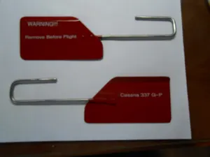
Parts listed for sale by vetted eBay sellers — confirmed on eBay at checkout.