Installation Guide For Vizion PMA Autopilot - Bendix/King
CESSNA 337G · Wiring Diagram
Overview
The Vizion Installation Guide provides detailed instructions for installing the Vizion PMA Autopilot system in various aircraft models, including the Cessna 185. It covers mounting, wiring, and operational considerations necessary for a successful installation. The guide is intended for aircraft technicians and pilots who are involved in the installation and setup of the autopilot system. It includes specific wiring diagrams, installation procedures, and troubleshooting tips to ensure the autopilot functions correctly once installed. The document emphasizes safety and compliance with installation standards to prevent any interference with aircraft operations.
- Maximum recommended viewing angle for the controller is 20 degrees.
- Use AWG #20 wire for all power and ground connections.
- Ensure that the autopilot master switch is easily accessible to the pilot.
- Connections to the pitot and static systems are required for autopilot functionality.
- Follow proper installation standards to avoid interference with aircraft operations.
Document
Source
Originally published by www.bendixking.com. Sprinkle hosts a reference copy with an added summary, specifications and searchable full text.
Document details
- Type
- Wiring Diagram
- Year
- 2019
- Pages
- 19
- File size
- 1.5 MB
- Publisher
- www.bendixking.com
Common. Rarer than 1% of the aircraft models we track.
Most owners only have the POH. Here's the essential set for the CESSNA 337G.
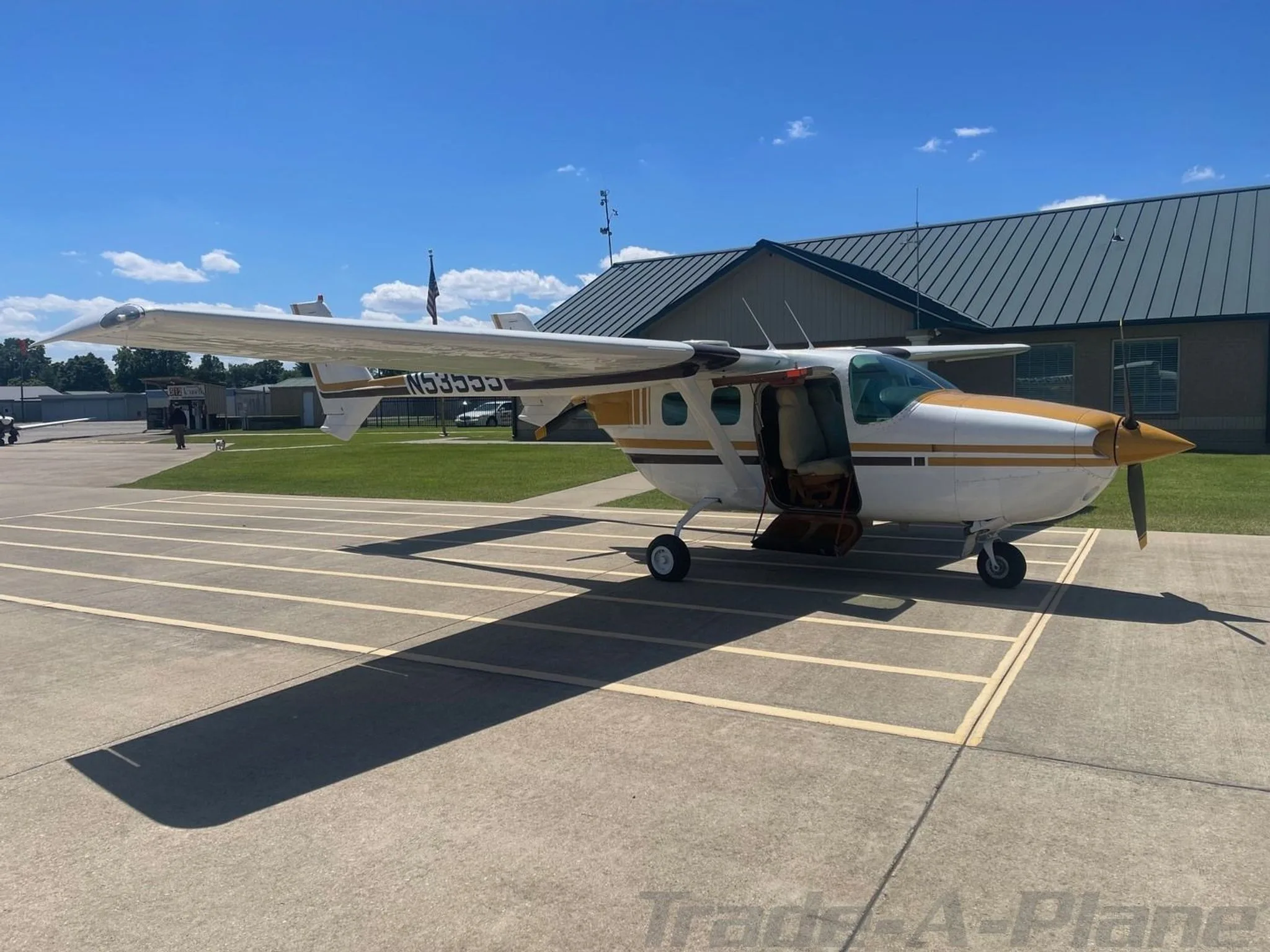
CESSNA 337G for sale now


Free — save the 337G to your watchlist and track it in one place.
More CESSNA 337Gmanuals & documents
See all 27 →- Inspection Authorization Information GuideType Certificate
- FUEL - FUEL STRAINER INSPECTIONMaintenance Manual
- Type Certificate Data SheetType Certificate
- CAPR 130-2, Civil Air Patrol Aircraft Maintenance ManagementTraining Manual
- Aircraft ChecklistsChecklist
- The National FAA Safety Team PresentsSupplemental Type Certificate
- R1224 REGULATOR INSTALLATION INSTRUCTIONS P/N 12-1001Wiring Diagram
- Advisory Circular: Standardized Procedures for Obtaining Approval of Data Used in the Performance of Major Repairs and Major AlterationsAdvisory Circular
- Advisory Circular: Part 135 Operator Aircraft Configuration InspectionTraining Manual
- Type Acceptance Report - TAR 17/21B/26 - CESSNA F337 SeriesOther Documents
- Airworthiness Directive Schedule Aeroplanes Cessna 337 SeriesService Bulletins
- Type Acceptance Report TAR 18/21B/4 – Cessna 337 SeriesOther Documents
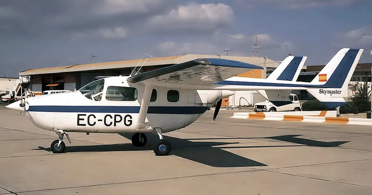
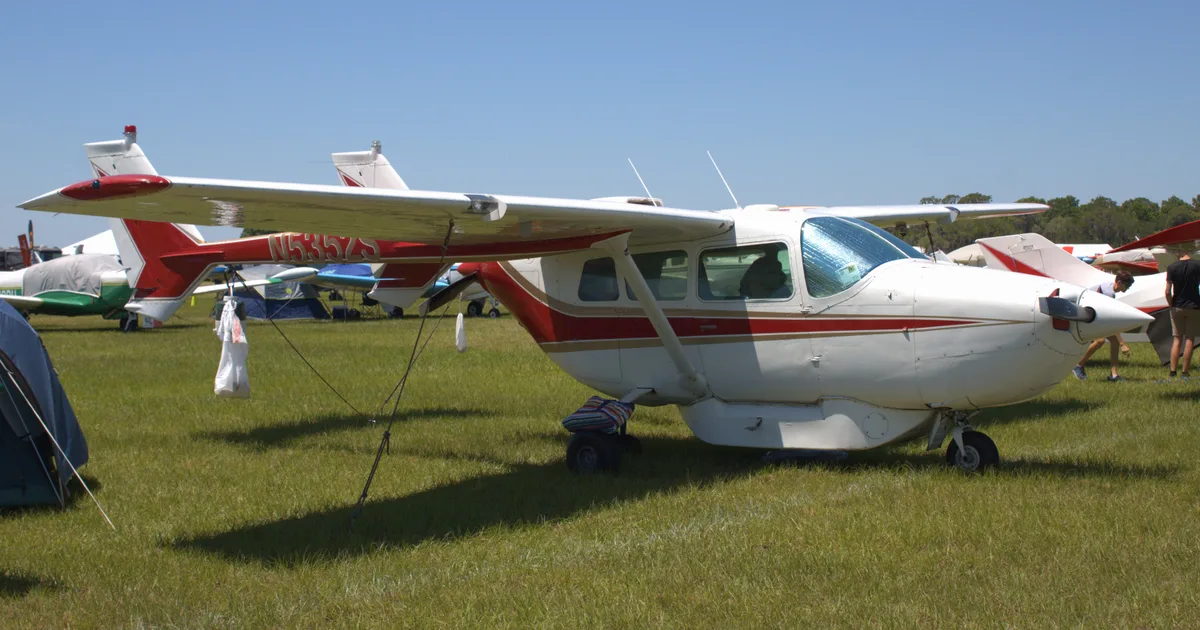
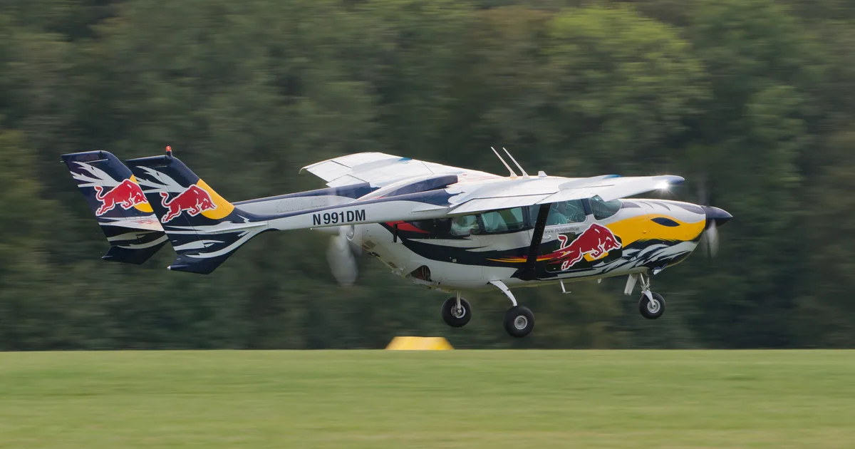
If you fly the CESSNA 337G, you may also be researching these.


In this document
Controller Installation
This section outlines the requirements for installing the Vizion controller unit in the aircraft instrument panel. It specifies the maximum viewing angle of 20 degrees and the maximum mounting angle of 10 degrees longitudinally. Proper mounting and support standards must be followed, and torque seal should be applied to all servo and linkage fasteners after installation.
Wiring Considerations
Wiring must use AWG #24 or larger, with AWG #20 for power and ground connections. It is crucial to avoid routing high current wires close to the autopilot controller and to ensure that wiring is not exposed to heat or electromagnetic interference. The autopilot master switch and circuit breaker must be easily accessible to the pilot.
Pitot / Static Connection
Connections to the pitot and static systems are required for the autopilot. The guide recommends using tee fittings near the aircraft’s altimeter for these connections. Proper construction of the static line is critical to avoid oscillation in pitch, and care must be taken to ensure adequate static ports.
Troubleshooting Guide
This section provides common issues that may arise during installation and operation of the autopilot system, along with possible causes and remedies. For example, if the autopilot does not power up, it may be due to a circuit breaker malfunction or incorrect wiring.
Appendices
The guide includes several appendices with installation information for various aircraft models, including Cessna 172, 177, 175, 180, 182, and 185, as well as PA-28 and PA-32 models. Each appendix provides specific details relevant to the installation of the Vizion autopilot in those aircraft.
Safety notes
- Do not drill holes that compromise structural integrity; consult the aircraft’s structural repair manual.
- Ensure wiring is not exposed to heat or electromagnetic interference.
Full document text
Rev: G Vizion Installation Guide TruTrak Doc: 166 1 Installation Guide For Vizion PMA Autopilot RESTRICTION ON USE, DUPLICATION, OR DISCLOSURE OF PROPRIETARY INFORMATION THIS DOCUMENT CONTAINS PROPRIETARY INFORMATION OF TRUTRAK FLIGHT SYSTEMS, INC. AND MAY NOT BE REPRODUCED, COPIED, DISCLOSED OR UTILIZED IN ANY WAY, IN WHOLE OR IN PART, WITHOUT THE PRIOR WRITTEN CONSENT OF TRUTRAK FLIGHT SYSTEMS, INC. Prepared by TruTrak Flight Systems, Inc. Function/Title Name Prepared by President Andrew Barker Prepared by GM Moss Foster Checked by GM Moss Foster Approved by President Andrew Barker Rev: G Vizion Installation Guide TruTrak Doc: 166 2 Table of Contents 1. Document Revision History ............................................................................. 3 Warning: ................................................................................................................... 4 2. Controller Installation ..................................................................................... 4 2.1. Mounting Considerations....................................................................................................................... 4 2.2. Wiring Considerations ............................................................................................................................ 4 2.3. Pitot / Static Connection ........................................................................................................................ 5 2.4. RFI / EMI Considerations....................................................................................................................... 5 2.5. Vizion Electrical Pin Out ......................................................................................................................... 6 2.6. Vizion Wiring Diagram............................................................................................................................ 8 2.7. Vizion Autopilot System Diagram .............................................................................................................. 9 3. Controller Cut-outs and Dimensions ............................................................ 10 3.1. Flat Pack Dimensions (8000-175 / 8000-185) ......................................................................... 10 3.2. Flat Pack Panel Cut-out ........................................................................................................................ 11 3.3. 2-1/4” Round Dimensions (8000-174 / 8000-183) ............................................................... 12 3.4. 3-1/8” Round Dimensions (8000-176 / 8000-184) ............................................................... 13 4. GPS Setup ......................................................................................................... 14 5. Vizion Ground Checkout ................................................................................ 14 6. Vizion First Flight Checkout .......................................................................... 15 7. Troubleshooting Guide .................................................................................. 17 8. Appendix A – Cessna 172 F-S Installation Information (Trutrak document 168) ......................................................................................................................... 18 9. Appendix B – Cessna 177 Installation Information (Trutrak document 169) ......................................................................................................................... 18 10. Appendix C – Cessna 175/172 All Models Installation Information (Trutrak document 242) ....................................................................................... 18 11. Appendix D – PA-28 and PA-32 Installation Information (Trutrak document 243) ....................................................................................................... 18 12. Appendix E – Cessna 180, 182-182D, 185 Installation Information (Trutrak document 255) ....................................................................................... 18 13. Appendix F – Cessna 182E-182T Installation Information (Trutrak document 256) ....................................................................................................... 18 14. Appendix G –PA-32 Installation Information (Trutrak document 267) 18 Rev: G Vizion Installation Guide TruTrak Doc: 166 3 1. Document Revision History Rev Description Pages Date Prelim Preliminary manual created 21 2-7-17 Init Updated sections for final product and added panel mount GPS information 24 6-14-17 Rev A Updated voltage to be 12 volts and formatting 23 7-12-17 Rev B Updated voltage to cover 24 volt servos 23 9-6-17 Rev C Updated wiring diagram, system diagram , added appendix c 23 1-8-18 Rev D Added appendix D 23 1-12-18 Rev E Added warning concerning aircraft modification 24 10-31-18 Rev F Added appendices E, F,G 24 11-14-18 Rev G Added new controller part numbers for BK bezel, added details for software PV.40, removed specifics for GPS setup as this was already in the Approved GPS List (doc 186) 19 5-15-19 Rev: G Vizion Installation Guide TruTrak Doc: 166 4 Warning: Do no drill any holes in the aircraft or aircraft structure that will result in less than recommended edge or fastener spacing distances. Reference your aircraft’s structural repair manual or Advisory Circular 43.13 for more information. If the installation requires less than recommended distances, do not proceed with the installation and contact Trutrak Flight Systems for further instruction. 2. Controller Installation 2.1.Mounting Considerations The Vizion controller unit is designed to mount in the aircraft instrument panel within view and reach of the pilot. Maximum recommended viewing angle should be no more than 20 deg. The maximum mounting angle the Vizion can accommodate is
Show full textShow less
10 degrees longitudinal (pitch) axis and 0 degrees lateral (roll or yaw) axis. The location should be such that the controller unit is not blocked by the glare shield on top, or by the throttles, control yoke, etc. on the bottom. Use appropriate aircraft installation standards for mounting and support of the autopilot controller. After completion of mechanical installation, apply torque seal (Cross Check A498M or equivalent) to all servo and servo linkage fasteners. 2.2.Wiring Considerations Use AWG #24 or larger wire for all connections unless otherwise specified. The standard crimp pin contacts supplied in the connector kit are compatible with up to AWG #20 wire. AWG #20 shall be used for all power and ground connections. Do not attach any wires to the outside of the autopilot controller or route high current wires within six (6) inches of the controller. Ensure that routing of the wiring is not exposed to sources of heat, RF or EMI. Check that there is ample space for the cabling and mating connectors. Avoid sharp bends in cabling and routing near aircraft control cables. Do not route the COM antenna coax within twelve (12) inches of any autopilot components. • Ensure that the autopilot master switch is mounted in a location that is easily accessible to the pilot / crew. • Ensure that the autopilot circuit breaker is mounted in a location that is easily accessible to the pilot / crew. • Ensure that the Control Wheel Steering button / emergency autopilot disconnect switch is mounted on the pilot’s yoke / stick. This button must be installed, must be red in color, and must be labeled as AP CWS or AP DISCO or AP CUTOFF. Rev: G Vizion Installation Guide TruTrak Doc: 166 5 • Ensure that the Emergency Level button is located in a clearly visible and accessible portion of the panel. This button must be accessible to both pilot and copilot. 2.3.Pitot / Static Connection All TruTrak autopilots require connections to the pitot and static systems. The preferred method of this connection would be tee fittings near the aircraft’s altimeter. The static line for the autopilot requires due care in its construction, as excessive lag or insufficient static orifices can cause the autopilot to oscillate (hunt) in pitch. Although there is compensation within the autopilot sufficient to handle moderate amounts of lag, the importance of a good static port and line cannot be overstated. In some cases problems can be caused by having a large number of devices (including the autopilot) connected to a single, insufficient, static port. In other cases, the static line itself is adequate but there are one or more devices connected to the same line, one of which has a large static reservoir. A simple remedy for this problem if it occurs is a tee-fitting near the static port, and a dedicated line to the autopilot only. Obviously, an insufficiently-large orifice coupled with large static reservoirs can aggravate the problems associated with lag. 2.4.RFI / EMI Considerations The autopilot controller is shielded and does not generate any appreciable level of electromagnetic interference. Moreover, the servo lines (except for power and ground) are low-current and cannot contribute to RF interference. The servo power and ground lines do have switching currents through them, but so long as there are no parallel runs of servo power and ground lines with such things as poorly-shielded antenna lines or strobe light power lines, there is no need to shield the servo harnesses. The autopilot itself has been internally protected from RF interference and has been tested under fairly extreme conditions, such as close proximity to transmitting antennas. However, it is always good practice to ensure that such antennas are properly shielded and not routed directly over or under sensitive panel-mounted electronic equipment. Most problems in this area are the result of improper RF shielding on transmitting antennas, microphone cables, and the like. The most sensitive input to the autopilot is the Control Wheel Steering switch input. This line should not be routed in parallel with transmitting antennas or other sources of known RF interference. If necessary, it can be shielded with the shield connection to pin 13 of the autopilot connector. Rev: G Vizion Installation Guide TruTrak Doc: 166 6 2.5.Vizion Electrical Pin Out The table below provides a brief explanation of each pin function on the main 25-pin connector P101. P10 1 Pin Function Notes 1 Used for external Emergency AP Level button connection. 2 Used for external Emergency AP Level button connection. 3 Control Wheel Steering. Connect as shown in wiring diagram to a RED SPST momentary switch located on the aircraft control yoke or stick to remotely disconnect the autopilot. This is also used for the control wheel steering function. 4 Pitch Servo Torque Control. A signal from the autopilot to the pitch servo, which sets the amount of torque to be delivered by the servo. 5 Pitch Servo Trim Sensor. A signal from the pitch servo to the autopilot, which indicates an out-of-trim condition and its direction. 6 Pitch Servo Trim Sensor. A second signal from the pitch servo to the autopilot, which indicates an out-of-trim condition and its direction. 7 RS-232 Output. Output for communication with G3X or other system to display autopilot mode information. 8 Pitch Servo control lines. These lines cause the stepper motor in the pitch servo to run in the appropriate direction at the desired velocity. They are small-signal lines and do not have any substantial current-carrying capability or require any special shielding. Connect to pitch servo as shown on wiring diagram. 9 10 11 12 Audio annunciator output Connect to optional audio annunciator. Designed to drive Mallory Sonalert SC628 type device. 13 Ground Connection. Provide #20 AWG to common grounding point. 14 ARINC 429 Input A 15 ARINC 429 Input B 16 Roll Servo Torque Control. A signal from the autopilot to the roll (aileron) servo, which sets the amount of torque to be delivered by the servo. Rear 25-Pin Connector P101 viewed from rear of unit 1 20 21 22 23 24 25 2 3 4 5 6 7 8 9 10 11 12 13 14 15 16 17 18 19 View of P101 Facing Rear of Programmer DIGIFLIGHT II PINOUT DESCRIPTION, MAIN I/O CONNECTOR P101 PIN FUNCTION Ground connection for Pitch Reverse Jumper. 1 2 3 4 5 6 7 8 9 10 11 12 13 14 15 16 17 18 19 20 21 22 23 24 25 Pitch Reverse Jumper. See note 3 on External Wiring Diagram. CONTROL WHEEL SWITCH PITCH SERVO TORQUE CONTROL PITCH SERVO TRIM SENSOR AUTOPILOT MASTER ( +12 to +28 VDC ) AUX RS-232 OUT (FUTURE EXPANSION) PITCH SERVO PH2N PITCH SERVO PH2P PITCH SERVO PH1N PITCH SERVO PH1P No Connection. Reserved for future expansion. GROUND ( - ) ARINC-429 (A) INPUT ARINC-429 (B) INPUT ROLL SERVO TORQUE CONTROL GPS AVIATION FORMAT OR NMEA-0183 SERIAL INPUT AUX RS-232 IN (FUTURE EXPANSION) AUTOPILOT POWER (INTERNALLY CONNECTED TO PIN 6) ROLL SERVO PH2N ROLL SERVO PH2P ROLL SERVO PH1N ROLL SERVO PH1P No Connection. Reserved for future expansion. No Connection. Reserved for future expansion. Rev: G Vizion Installation Guide TruTrak Doc: 166 7 17 Primary Serial Input. Baud rate selectable 1200, 2400, 4800 or 9600 baud. Automatically decodes NMEA-0183, Garmin Aviation Format, or Apollo/UPSAT Moving-Map or GPSS format. Provides directional reference to the autopilot. 18 Unused 19 Autopilot Master (+12 OR +24 V DC). The autopilot itself draws less than 0.5 ampere. Most of the current required by the autopilot system is used by the servos (up to 2A per servo at 12 Volts). 20 21 22 23 Roll (aileron) Servo control lines. These lines cause the stepping motor in the roll servo to run in the appropriate direction at the desired velocity. They are small-signal lines and do not have any substantial current-carrying capability or require any special shielding. Connect to roll servo as shown on wiring diagram. 24 Unused. 25 Unused. Rev: G Vizion Installation Guide TruTrak Doc: 166 8 2.6.Vizion Wiring Diagram Rev: G Vizion Installation Guide TruTrak Doc: 166 9 2.7. Vizion Autopilot System Diagram Rev: G Vizion Installation Guide TruTrak Doc: 166 10 3. Controller Cut-outs and Dimensions 3.1. Flat Pack Dimensions (8000-175 / 8000-185) Rev: G Vizion Installation Guide TruTrak Doc: 166 11 3.2.Flat Pack Panel Cut-out Rev: G Vizion Installation Guide TruTrak Doc: 166 12 3.3. 2-1/4” Round Dimensions (8000-174 / 8000-183) Rev: G Vizion Installation Guide TruTrak Doc: 166 13 3.4. 3-1/8” Round Dimensions (8000-176 / 8000-184) Rev: G Vizion Installation Guide TruTrak Doc: 166 14 4. GPS Setup For known setup and cable information to connect GPS units to the Vizion autopilot, see the document “Approved GPS List (186)” on the TruTrak website Certified Documents and Manuals page. This document provides setup information for panel mounted and handheld GPS units that have been verified to be compatible with TruTrak autopilots. If your GPS is not included in the Approved GPS List (186), consult your GPS manual for NMEA output setup. The autopilot must have a direct RS-232 connection with the handheld GPS. To allow easy removal of the handheld GPS, a 9 pin D subminiature connector in your panel is recommended, which will also allow the use of the aircraft electrical system to power the handheld GPS. 5. Vizion Ground Checkout Once installation and setup of the autopilot are complete, (see appropriate appendix for servo installation, wiring harness routing, and autopilot controller settings) a ground checkout is required before the first flight of the system. This procedure will verify correct servo direction and pitot / static system connection. The following steps should be used to do a ground checkout prior to powering or engaging autopilot in flight. 1. Apply power to autopilot and servos and GPS (if equipped). If GPS equipped ensure a GPS has a position fix. 2. Verify autopilot display shows either NO FIX or GPS OK in the upper left. 3. Center both aileron and elevator control surfaces. 4. Using a calibrated PITOT / STATIC test box, connected to both PITOT and STATIC ports of the aircraft, apply an airspeed to the system within above MINIMUM AIRSPEED but below MAXIMUM AIRSPEED (These values are given in the appropriate appendix for the aircraft make / model). 5. Engage the autopilot with a PRESS of the KNOB on the face of the autopilot. 6. Verify that both roll and pitch servos have engaged and are holding aircraft controls. 7. Adjust PITOT pressure to lower the airspeed to below MINIMUM AIRSPEED. 8. Verify that autopilot display shows MIN AS within approximately 3 knots of calibrated airspeed indicator on test box. 9. Adjust PITOT pressure to increase the airspeed to above MAXIMUM AIRSPEED. 10. Verify that autopilot display shows MAX AS within approximately 3 knots of calibrated airspeed indicator on test box. Rev: G Vizion Installation Guide TruTrak Doc: 166 15 11. Return PITOT pressure to normal range between MINIMUM and MAXIMUM AIRSPEED. 12. Adjust STATIC pressure to lower altitude at a few hundred feet per minute. 13. Verify that stick or yoke moves aft. 14. Adjust STATIC pressure to increase altitude at a few hundred feet per minute. 15. Verify that stick or yoke moves forward. 16. ROTATE KNOB clockwise to command a turn to the right. 17. Verify that stick or yoke moves to roll the aircraft to the right. 18. ROTATE KNOB counter-clockwise to command a turn the left, make sure to rotate far enough to actually command a left turn. 19. Verify that the stick or yoke moves to roll the aircraft to the left. 20. Disengage autopilot with a PRESS of the CWS button. 21. Verify that servos have disconnected, autopilot display shows AP OFF, and controls are again free. 22. Center both aileron and elevator control surfaces. 23. Engage autopilot with a PRESS of the AP LEVEL button. 24. Verify that both roll and pitch servos have engaged and are holding aircraft controls. 25. PRESS KNOB to move cursor to SVS and ROTATE KNOB clockwise to select a 300 fpm VS climb. 26. Verify that stick or yoke moves aft. 27. Apply a force to the stick or yoke to resist the aft movement 28. Verify that the center of the autopilot display shows the letters UP with an arrow pointing up above them. (this is the indication to trim the aircraft for nose up). 29. PRESS KNOB to move cursor to SVS and ROTATE KNOB counter- clockwise to select a -300 fpm VS climb. 30. Verify that stick or yoke moves forward. 31. Apply a force to the stick or yoke to resist the forward movement 32. Verify that the center of the autopilot display shows the letters DN with an arrow pointing down below them (this is the indication to trim the aircraft for nose down). 33. Disengage the autopilot with a PUSH and HOLD of the knob, release when the display shows AP OFF. 34. Verify that both servos have disconnected and controls are again free. If steps 1-34 are all verified then the autopilot is ready for a confirmation flight. 6. Vizion First Flight Checkout Prior to performing Vizion first flight, it is strongly recommended that the pilot be familiar with the operation of the Vizion system. Reading though both the Vizion AFMS (TruTrak Doc 176) and the Vizion Operating Manual (TruTrak Doc 167) is Rev: G Vizion Installation Guide TruTrak Doc: 166 16 recommended. It would also be beneficial to spend some time operating the Vizion autopilot system on the ground to ensure familiarity with modes and controls. 1. Apply power to autopilot and servos and GPS (if equipped). If GPS equipped ensure GPS has a position fix. 2. If GPS equipped, verify autopilot display shows TRK (if aircraft is moving at greater than 15 knots ground speed) and the current track in the upper left. 3. Synchronize autopilot altimeter to aircraft altimeter, CLICK ALT button two times and ROTATE KNOB until displayed altitude matches that of the aircraft altimeter. 4. Engage the autopilot with a CLICK of the KNOB on the face of the autopilot. 5. Verify that both roll and pitch servos have engaged and are holding aircraft controls. The autopilot should synchronize to the current track and vertical speed being flown at the time. 6. ROTATE KNOB clockwise to command a turn of about 60 degrees to the right. (If not GPS equipped, then command a 10-15 degree bank angle) 7. Verify that the aircraft follows the commands and rolls out within a few degrees of the selected track. (If not GPS equipped, the turn must be manually stopped by rotating the KNOB to zero bank) 8. ROTATE KNOB counter-clockwise to command a turn of about 60 degrees the left. 9. Verify that the aircraft follows the commands and rolls out within a few degrees of the selected track. (If not GPS equipped, the turn must be manually stopped by rotating the KNOB to zero bank) 10. If GPS equipped, enter a flight plan or direct to into the GPS. 11. CLICK MODE button to engage either GPS NAV or GPSS. 12. Ensure that autopilot follows GPS flight plan / direct to. 13. If Aspen / G5 equipped, select Aspen / G5 ARINC source. 14. CLICK MODE button to engage ASPEN / EXT HDG, EXT ALT mode. 15. Ensure that autopilot follows heading bug and / or altitude bug. 16. Disengage autopilot with a CLICK of the CWS button. 17. Verify that servos have disconnected, autopilot display shows AP OFF, and controls are again free. 18. Engage autopilot with a CLICK of the AP LEVEL button. 19. Verify that both roll and pitch servos have engaged and are holding aircraft controls. (Display will show BANK mode for several seconds and then will transition to TRK mode if GPS equipped) 20. CLICK ALT button to enter altitude select mode. 21. ROTATE KNOB to select an altitude approximately 300 feet lower, CLICK KNOB to move cursor to VS field, ROTATE KNOB to select a climb rate of approximately -300 fpm. CLICK KNOB to enter altitude select mode. 22. Verify that aircraft descends to and levels off within 20 feet of selected altitude (If trim indication appears, trim aircraft accordingly). Rev: G Vizion Installation Guide TruTrak Doc: 166 17 23. Disengage the autopilot with a PRESS and HOLD of the knob, release when the display shows AP OFF. 24. Ensure that AEP is in STBY mode. Display should show AEP STBY, if display does not show AEP STBY, CLICK MODE button to toggle AEP mode from AEP OFF to AEP STBY. 25. Manually fly aircraft to bank angle of approximately 45 degrees, verify that AEP engages (Display shows AEP ACTIVE) and roll servo puts force into the control system moving controls in a direction to lower the bank angle. 26. Verify that AEP goes back to STBY when bank angle decreases to approximately 35 degrees. 7. Troubleshooting Guide Autopilot System Fault Possible cause Possible remedy Autopilot does not power up when circuit breaker / autopilot master is engaged Circuit breaker malfunction Inspect and replace circuit breaker if necessary. Autopilot not wired to ground Verify and fix any wiring errors. Roll servo does not engage when autopilot system is engaged Roll servo wiring is faulty Install servo harness tester in place of roll servo, and / or verify correct wiring. Pitch servo does not engage when autopilot system is engaged Pitch servo wiring is faulty Install servo harness tester in place of pitch servo, and / or verify correct wiring. Roll servo moves in the wrong direction during ground test Servo wiring incorrect or servo direction not correct in setup. Verify correct wiring and / or change roll servo direction in autopilot setup. Pitch servo moves the wrong direction during ground test; trim indicates incorrect direction. Servo wiring incorrect or servo direction not correct in setup. Verify correct wiring and / or change pitch servo direction in autopilot setup. Pitch servo moves the wrong direction during ground test; trim indicates correct direction. Servo wiring incorrect. Verify correct wiring Autopilot controller displays NO GPS GPS is not configured correctly Configure RS232 output on GPS. Autopilot controller baud rate is set incorrectly Enter lateral setup menu of autopilot controller, set baud rate to match that of GPS GPS wiring is faulty Check continuity of RS232 transmit wire from GPS to pin 17 of autopilot controller Rev: G Vizion Installation Guide TruTrak Doc: 166 18 8. Appendix A – Cessna 172 F-S Installation Information (Trutrak document 168) Contact TruTrak for appropriate installation information. 9. Appendix B – Cessna 177 Installation Information (Trutrak document 169) Contact TruTrak for appropriate installation information. 10. Appendix C – Cessna 175/172 All Models Installation Information (Trutrak document 242) Contact TruTrak for appropriate installation information. 11. Appendix D – PA-28 and PA-32 Installation Information (Trutrak document 243) Contact TruTrak for appropriate installation information. 12. Appendix E – Cessna 180, 182-182D, 185 Installation Information (Trutrak document 255) Contact TruTrak for appropriate installation information. 13. Appendix F – Cessna 182E-182T Installation Information (Trutrak document 256) Contact TruTrak for appropriate installation information. 14. Appendix G –PA-32 Installation Information (Trutrak document 267) Contact TruTrak for appropriate installation information. Rev: G Vizion Installation Guide TruTrak Doc: 166 19 TruTrak Flight Systems, Inc.
What's in the CESSNA 337G TCDS
A Type Certificate Data Sheet (TCDS) is the FAA's record of what an aircraft type was approved as. It is the source of truth for weights, seating, fuel and the rules the design was certified against. Expand any line to see what it means.
1,879 CESSNA 337G parts for sale
See all →
Parts listed for sale by vetted eBay sellers — confirmed on eBay at checkout.